EP1618577B1 - Vakuum-unterbrecherschalter - Google Patents
Vakuum-unterbrecherschalter Download PDFInfo
- Publication number
- EP1618577B1 EP1618577B1 EP04723435A EP04723435A EP1618577B1 EP 1618577 B1 EP1618577 B1 EP 1618577B1 EP 04723435 A EP04723435 A EP 04723435A EP 04723435 A EP04723435 A EP 04723435A EP 1618577 B1 EP1618577 B1 EP 1618577B1
- Authority
- EP
- European Patent Office
- Prior art keywords
- circuit breaker
- vacuum circuit
- contact
- breaker according
- traction
- Prior art date
- Legal status (The legal status is an assumption and is not a legal conclusion. Google has not performed a legal analysis and makes no representation as to the accuracy of the status listed.)
- Expired - Lifetime
Links
- 238000009413 insulation Methods 0.000 claims abstract description 13
- 239000012212 insulator Substances 0.000 claims abstract description 12
- 238000001125 extrusion Methods 0.000 claims abstract description 9
- 238000000034 method Methods 0.000 claims abstract description 9
- 230000008569 process Effects 0.000 claims abstract description 9
- 229910000838 Al alloy Inorganic materials 0.000 claims abstract description 5
- 239000012634 fragment Substances 0.000 claims abstract description 5
- 239000000463 material Substances 0.000 claims abstract description 5
- 230000007246 mechanism Effects 0.000 claims abstract description 5
- 238000005096 rolling process Methods 0.000 claims description 3
- 238000010002 mechanical finishing Methods 0.000 claims description 2
- 230000003247 decreasing effect Effects 0.000 claims 1
- 229910052751 metal Inorganic materials 0.000 abstract description 2
- 239000002184 metal Substances 0.000 abstract description 2
- 230000009467 reduction Effects 0.000 description 5
- 230000006835 compression Effects 0.000 description 4
- 238000007906 compression Methods 0.000 description 4
- 238000004519 manufacturing process Methods 0.000 description 4
- 238000001816 cooling Methods 0.000 description 3
- 230000015556 catabolic process Effects 0.000 description 2
- 238000005520 cutting process Methods 0.000 description 2
- 238000009826 distribution Methods 0.000 description 2
- 230000001052 transient effect Effects 0.000 description 2
- 230000009471 action Effects 0.000 description 1
- 230000000712 assembly Effects 0.000 description 1
- 238000000429 assembly Methods 0.000 description 1
- 238000005266 casting Methods 0.000 description 1
- 239000004020 conductor Substances 0.000 description 1
- 238000010276 construction Methods 0.000 description 1
- 230000000694 effects Effects 0.000 description 1
- 230000005684 electric field Effects 0.000 description 1
- 238000004870 electrical engineering Methods 0.000 description 1
- 230000004907 flux Effects 0.000 description 1
- 230000006872 improvement Effects 0.000 description 1
- 230000001939 inductive effect Effects 0.000 description 1
- 229920002379 silicone rubber Polymers 0.000 description 1
- 239000004945 silicone rubber Substances 0.000 description 1
- 230000009295 sperm incapacitation Effects 0.000 description 1
- 238000004804 winding Methods 0.000 description 1
Images


Classifications
-
- H—ELECTRICITY
- H01—ELECTRIC ELEMENTS
- H01H—ELECTRIC SWITCHES; RELAYS; SELECTORS; EMERGENCY PROTECTIVE DEVICES
- H01H33/00—High-tension or heavy-current switches with arc-extinguishing or arc-preventing means
- H01H33/60—Switches wherein the means for extinguishing or preventing the arc do not include separate means for obtaining or increasing flow of arc-extinguishing fluid
- H01H33/66—Vacuum switches
- H01H33/666—Operating arrangements
- H01H33/6662—Operating arrangements using bistable electromagnetic actuators, e.g. linear polarised electromagnetic actuators
-
- H—ELECTRICITY
- H01—ELECTRIC ELEMENTS
- H01H—ELECTRIC SWITCHES; RELAYS; SELECTORS; EMERGENCY PROTECTIVE DEVICES
- H01H1/00—Contacts
- H01H1/58—Electric connections to or between contacts; Terminals
- H01H1/5833—Electric connections to or between contacts; Terminals comprising an articulating, sliding or rolling contact between movable contact and terminal
-
- H—ELECTRICITY
- H01—ELECTRIC ELEMENTS
- H01H—ELECTRIC SWITCHES; RELAYS; SELECTORS; EMERGENCY PROTECTIVE DEVICES
- H01H33/00—High-tension or heavy-current switches with arc-extinguishing or arc-preventing means
- H01H33/60—Switches wherein the means for extinguishing or preventing the arc do not include separate means for obtaining or increasing flow of arc-extinguishing fluid
- H01H33/66—Vacuum switches
- H01H33/6606—Terminal arrangements
- H01H2033/6613—Cooling arrangements directly associated with the terminal arrangements
-
- H—ELECTRICITY
- H01—ELECTRIC ELEMENTS
- H01H—ELECTRIC SWITCHES; RELAYS; SELECTORS; EMERGENCY PROTECTIVE DEVICES
- H01H33/00—High-tension or heavy-current switches with arc-extinguishing or arc-preventing means
- H01H33/02—Details
- H01H33/24—Means for preventing discharge to non-current-carrying parts, e.g. using corona ring
-
- H—ELECTRICITY
- H01—ELECTRIC ELEMENTS
- H01H—ELECTRIC SWITCHES; RELAYS; SELECTORS; EMERGENCY PROTECTIVE DEVICES
- H01H9/00—Details of switching devices, not covered by groups H01H1/00 - H01H7/00
- H01H9/16—Indicators for switching condition, e.g. "on" or "off"
Definitions
- the invention is related to electrical engineering, particularly to vacuum circuit breaker.
- the vacuum circuit breaker having vacuum interrupter, electromagnetic drive, opening springs and compression springs is known [1].
- the closest in design is the vacuum circuit breaker of TEL line, having drives in segregated - phase arrangement with magnetic latch and synchronizing shaft [2].
- Disadvantages of this design include considerable length of pulling insulator, relatively high resistance of movable conducting element (flexible current shunt), complexity of magnetic actuator, low rated current due to hindered natural cooling of contact terminals, difficulty in manual tripping and remote mechanical indication of main contact positions, difficulties in connecting up socket contacts and designing interlock mechanisms for various application projects.
- the invention solves the problem of providing a vacuum circuit breaker having reduced dimensions and cost, while increasing main performance parameters.
- the technical effect of applying the invention as claimed includes: reduction in traction insulator length, reduction in resistance of movable conducting element, simplification and cost reduction of the magnetic actuator, increase of rated current due to improvement in cooling contact terminals, reduction of the force required for manual tripping, solution of the problem of remote mechanical indication for main contacts, connecting up socket contacts and their simplified designs, facilitation of the task of hooking up interlock mechanisms.
- the vacuum circuit breaker is characterized in that the traction insulation therein is embodied in such a way that component parts energized by different potentials are covered with insulation, immovable part of the insulation being embodied with a tubular fragment located coaxially inside the insulation sleeve, which is a part of the traction insulator, and resilient conductive spirals are used as movable conducting elements, having a possibility of rolling between surfaces, at least one of which possesses teeth, with the teeth oriented in the direction of motion, two convolutions of said spirals being located between the teeth, and drive magnetic systems constitute two bowl - shaped components made of high - coercivity material with a coil located inside, one bowl - shaped component being attached to the circuit breaker base, the other being attached to the traction insulator, and contact terminals are made of aluminium alloy using extrusion process followed by subsequent mechanical finishing, and the manual deenergization generator constitutes a closed magnetic system having a possibility of mechanical opening thereof, comprising permanent magnet and coil electrically connected with
- the essence of the invention consists in the fact that the traction insulator and immovable insulation tubular fragment provide labyrinth air-gap between high potential and the earth in such a way that the breakdown path in the air has segments directed oppositely to the direction of the electrical field.
- the drive magnetic system consisting of two bowl - shaped component parts made of high - coercivity material makes it possible to implement a simple and reliable drive with magnetic latch.
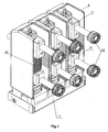
- the general layout of the vacuum circuit breaker is presented in Fig.1 , the plane section for a module of one of the phases is presented for the vacuum circuit breaker in enabled position in Fig. 2 , and for the vacuum circuit breaker in disabled position in Fig. 3 , the contact terminals are shown in Fig. 4 , the principle of contacting for the spiral current collector in cases of one and two toothed surfaces is presented in Fig. 5 and Fig. 6 accordingly, the plane section of the manual deenergization generator is provided in Fig. 7 , the construction design of a socket contact is presented in Fig. 8 .
- the vacuum circuit breaker comprises phase modules mounted on metal base 1, inside which drives with magnetic latch are situated, comprising stator 2, armature 3 and coil 4, opening spring 5, synchronizing 6 and interlock 7 shafts, block contacts.
- Cam 8 is situated at the end of interlock shaft 7.
- the phase modules comprise supporting insulators 9, with vacuum chambers 10 embedded in silicone rubber positioned inside, contact terminals 11, 12, compression spring 13 and traction insulators 14.
- Drive stator 2 faced to contact terminal 11 is covered with hard insulation 15 with the tubular fragment 16.
- Spiral conducting elements 17 are situated in the clearance between contact terminal 11 I and movable contact bush 18.
- Indicator of contact positions 19 is connected with synchronizing shaft 6 with the encapsulated wire shaft.
- Manual deenergization generator 20 with armature 21 is electrically connected with windings of drive coils 4.
- Socket contacts 22 comprise separators 23, lamels 24 and plate springs 25.
- the device operates in the following way.
- a current pulse is provided to drive coils 4, closing stator 2 and armature 3 occurs, which is accompanied by compression of opening 5 and compression 13 springs, and closing contacts of vacuum chambers 10 occurs.
- Stator 2 and armature 3 may be in closed position infinitely, because they are made of high - coercivity material, retaining therein the residual magnetic flux.
- a negative - sequence current pulse is provided to coils 4
- "resetting" of the magnetic latch from the drive occurs, and by the action of springs 5 and 13, the drive returns to the position presented in Fig. 3 , contacts of vacuum chambers 10 are disconnected.
- the synchronizing shaft turns to a certain angle, moving the indicator 19 from one position to another.
- the shaft turn brings about actuation of block contacts (not shown in the Fig. 3 ).
- block contacts not shown in the Fig. 3 .
- spiral conducting elements 17 roll between elements 18 and 11. ensuring permanent contact between them.
- Forces of contact pressures are shown by arrows in Fig. 5 and Fig. 6 for turns of resilient spiral conducting elements in cases of one ( Fig. 5 ) or two ( Fig. 6 ) toothed surfaces.
- Fig. 2 The principle of labyrinth insulation is shown in Fig. 2 , wherein possible path of the breakdown in air between terminal 11 and component parts energized by the earth potential is indicated by arrows.
- manual deenergization may be performed using manual deenergization generator 20 by moving its armature 21, resulting in opening the magnetic system enabling the permanent magnet, and inducing a current pulse in the coil of manual deenergization generator 20, fed to drive coils 4, leading to "resetting" of the latter from the magnetic latch.
- Manual deenergization also may be performed by mechanical disconnection of stator 2 from armature 3 through turning interlock shaft 7, which detaches armature 3 from stator 2 with its cam.
- Turning of the interlock shaft 7 is performed by 90°, and its design is such that it may be situated only in one of two stable positions of Fig. 2 and Fig. 3 .
- Multiple contact spiral current collector 17 enables obtaining low values of transient resistance, unobtainable for other designs of similar dimensions.
- Manual deenergization generator 20 and indicator of contact position 19 may be mounted in any convenient place because they are not in a rigid mechanical connection with the vacuum circuit breaker.
- interlock shaft makes it possible to develop simple and reliable interlock systems for any type of factory - assembled distribution devices.
Landscapes
- Physics & Mathematics (AREA)
- Electromagnetism (AREA)
- High-Tension Arc-Extinguishing Switches Without Spraying Means (AREA)
- Driving Mechanisms And Operating Circuits Of Arc-Extinguishing High-Tension Switches (AREA)
- Switches Operated By Changes In Physical Conditions (AREA)
- Gas-Insulated Switchgears (AREA)
- Keying Circuit Devices (AREA)
Claims (8)
- Vakuum-Unterbrecherschalter, enthaltend Vakuumkessel, Bezugsun Schubisolierung, Antriebe mit getrennten Phasen und magnetischen Schnappern und eine gemeinsame Synchronisierwelle, dadurch gekennzeichnet, daß zwecks der Verkleinerung der Außenmaße die Schubisolierung so ausgebildet ist, daß die Schaltungselemente, die verschiedene Potenziale haben, mit der Isolierung verdeckt sind, wobei der unbewegliche Teil der Isolierung ein röhriges Fragment hat, das gleichachsig innerhalb des Isolierglases untergebracht ist, wobei das Isolierglas ein Teil des Schubisolators ist.
- Vakuum-Unterbrecherschalter nach Anspruch 1, dadurch gekennzeichnet, daß als ein stromführendes Element elastische Spiralen genutzt sind, die zwischen den Flächen abrollen können, und wenigstens eine Spirale verzahnt ist, und die Zähne in der Richtung der Bewegung gerichtet sind, wobei zwei Windungen der genannten Spiralen zwischen den Zähnen liegen.
- Vakuum-Unterbrecherschalter nach Anspruch 1 oder 2, dadurch gekennzeichnet, daß die Magnetiksysteme der Antriebe zwei Schalen aus Dauermagnetwerkstoff mit einer innenliegenden Rolle vorstellen, wobei eine Schale zu der Gründung des Unterbrecherschalters befestigt ist und die andere zu dem Schubisolator befestigt ist.
- Vakuum-Unterbrecherschalter nach einem der Ansprüche 1, 2, 3, dadurch gekennzeichnet, daß die Kontaktterminale aus einer Aluminiumlegierung mittels Strangpreßverfahrens mit anschließender mechanischen Bearbeitung hergestellt sind.
- Vakuum-Unterbrecherschalter nach einem der Ansprüche 1, 2, 3, 4, dadurch gekennzeichnet, daß der Unterbrecherschalter einen Handauflösungsgenerator hat, der ein geschlossenes Magnetiksystem vorstellt, das mechanisch abgeschaltet werden kann und einen Dauermagnet und eine Spule hat, wobei die Spule mit den Spulen der Antriebe des Shalters elektrisch verbunden ist und die Handauflösungsdrucktaste fest mit dem Element des Magnetiksystems auf solche Weise verbunden ist, daß die Richtung der Betätigung der Öffnungsrichtung des Magnetiksystems entspricht.
- Vakuum-Unterbrecherschalter nach einem der Ansprüche 1 bis 5, dadurch gekennzeichnet, daß der Unterbrecherschalter eine abgesetzte Schaltstellungsanzeige hat, verbunden mit dem Mechanismus der Synchronisierwelle des Unterbrecherschalters mittels Zugmittel in Form eines ummantelten Seiles.
- Vakuum-Unterbrecherschalter nach einem der Ansprüche 1 bis 6, dadurch gekennzeichnet, daß der Unterbrecherschalter Steckkontakte hat, umfassend Separatoren aus Aluminiumlegierung, die mittels Extrudieren hergestellt ist.
- Vakuum-Unterbrecherschalter nach einem der Ansprüche 1 bis 7, dadurch gekennzeichnet, daß der Unterbrecherschalter eine Blockrolle mit einem Nocken für mechanische Unterbrechung und Antriebsblockierung im Abschaltzustand und einen Hebel für elektrische Verriegelung umfasst.
Applications Claiming Priority (2)
| Application Number | Priority Date | Filing Date | Title |
|---|---|---|---|
| RU2003108296/09A RU2249874C2 (ru) | 2003-03-26 | 2003-03-26 | Вакуумный выключатель |
| PCT/RU2004/000114 WO2004086437A1 (en) | 2003-03-26 | 2004-03-25 | Vacuum circuit breaker |
Publications (3)
| Publication Number | Publication Date |
|---|---|
| EP1618577A1 EP1618577A1 (de) | 2006-01-25 |
| EP1618577A4 EP1618577A4 (de) | 2006-08-02 |
| EP1618577B1 true EP1618577B1 (de) | 2009-03-25 |
Family
ID=33095916
Family Applications (1)
| Application Number | Title | Priority Date | Filing Date |
|---|---|---|---|
| EP04723435A Expired - Lifetime EP1618577B1 (de) | 2003-03-26 | 2004-03-25 | Vakuum-unterbrecherschalter |
Country Status (8)
| Country | Link |
|---|---|
| EP (1) | EP1618577B1 (de) |
| CN (1) | CN100375211C (de) |
| AT (1) | ATE426910T1 (de) |
| DE (1) | DE602004020206D1 (de) |
| RU (1) | RU2249874C2 (de) |
| UA (1) | UA79370C2 (de) |
| WO (1) | WO2004086437A1 (de) |
| ZA (1) | ZA200508667B (de) |
Cited By (3)
| Publication number | Priority date | Publication date | Assignee | Title |
|---|---|---|---|---|
| CN102306589A (zh) * | 2011-05-31 | 2012-01-04 | 北京博瑞莱智能科技有限公司 | 低压永磁真空负荷开关 |
| CN102306585A (zh) * | 2011-07-15 | 2012-01-04 | 蒋通军 | 一种遥控及手动两用式电力高压保险开关 |
| CN102915870A (zh) * | 2012-11-13 | 2013-02-06 | 宁夏力成电气集团有限公司 | 一种具有闭合磁路的e形单稳态永磁机构 |
Families Citing this family (21)
| Publication number | Priority date | Publication date | Assignee | Title |
|---|---|---|---|---|
| DE102006041377B3 (de) * | 2006-08-29 | 2007-12-27 | Siemens Ag | Armatur |
| DE102006042101B4 (de) * | 2006-09-07 | 2008-09-25 | Switchcraft Europe Gmbh | Vakuumschalter für Mittel- und Hochspannungen |
| FR2920251B1 (fr) * | 2007-08-23 | 2009-11-13 | Areva T & D Sa | Dispositif de coupure pour appareillage electrique de commutation |
| RU2344506C1 (ru) * | 2007-08-30 | 2009-01-20 | Евгений Валерьевич Прохоренко | Вакуумный выключатель |
| JP5215238B2 (ja) * | 2009-05-28 | 2013-06-19 | 三菱電機株式会社 | 遮断器 |
| EP2461338B2 (de) * | 2010-12-03 | 2017-03-01 | ABB Schweiz AG | Schutzschalteranordnung für eine Mittelspannungs- bis Hochspannungsanwendung |
| FR2971080B1 (fr) * | 2011-02-02 | 2013-03-01 | Alstom Grid Sas | Appareillage d'ampoule a vide comprenant un moyen de verrouillage |
| US8729416B2 (en) | 2012-01-23 | 2014-05-20 | Electro-Mechanical Corporation | Circuit breaker remote tripping |
| US8729985B2 (en) | 2012-01-23 | 2014-05-20 | Electro-Mechanical Corporation | Switchgear visible disconnect mechanical interlock |
| US9070517B2 (en) | 2012-08-13 | 2015-06-30 | Electro-Mechanical Corporation | Vacuum interrupter and linear disconnect switch |
| RU2521609C2 (ru) * | 2012-11-01 | 2014-07-10 | Открытое акционерное общество "Всероссийский научно-исследовательский проектно-конструкторский и технологический институт электромашиностроения" | Вакуумный выключатель |
| RU2551443C2 (ru) * | 2013-02-13 | 2015-05-27 | Общество с ограниченной ответственностью "Астер Электро" | Модульный вакуумный выключатель |
| CN103367023B (zh) * | 2013-06-17 | 2015-12-02 | 北海银河产业投资股份有限公司 | 全绝缘真空断路器极柱 |
| RU2545163C1 (ru) * | 2013-10-02 | 2015-03-27 | Общество с ограниченной ответственностью "Научно-производственная фирма "Радиус" | Вакуумный выключатель |
| US20150332883A1 (en) * | 2014-05-14 | 2015-11-19 | Eaton Corporation | Electrical switching apparatus and linear actuator assembly therefor |
| GB2527800A (en) * | 2014-07-02 | 2016-01-06 | Eaton Ind Netherlands Bv | Circuit breaker |
| IT201700020449A1 (it) * | 2017-02-23 | 2018-08-23 | Giampietro Tosi | Gruppo interruttore in vuoto con sezionatore per media tensione |
| RU2684175C1 (ru) * | 2018-05-17 | 2019-04-04 | Акционерное общество "Радио и Микроэлектроника" | Трехфазный вакуумный выключатель |
| US10825625B1 (en) | 2019-06-07 | 2020-11-03 | Smart Wires Inc. | Kinetic actuator for vacuum interrupter |
| RU2721790C1 (ru) * | 2019-09-04 | 2020-05-22 | Евгений Юрьевич Парамонов | Механизм ручного отключения приводов высоковольтного вакуумного выключателя |
| RU2756294C1 (ru) * | 2020-11-05 | 2021-09-29 | Акционерное Общество "Электротехнические заводы "Энергомера" | Механизм ручного отключения привода высоковольтного вакуумного выключателя |
Family Cites Families (9)
| Publication number | Priority date | Publication date | Assignee | Title |
|---|---|---|---|---|
| DE2320744C3 (de) * | 1973-04-25 | 1981-05-07 | Fritz Driescher Spezialfabrik für Elektrizitätswerksbedarf, 5144 Wegberg | Steckvorrichtung |
| JPS56109416A (en) * | 1980-02-04 | 1981-08-29 | Meidensha Electric Mfg Co Ltd | Vacuum switching device |
| JPS57147829A (en) * | 1981-03-06 | 1982-09-11 | Tokyo Shibaura Electric Co | Vacuum breaker |
| SU1429190A1 (ru) * | 1986-12-18 | 1988-10-07 | Минусинское Отделение Всесоюзного Электротехнического Института Им.В.И.Ленина | Вакуумный выключатель |
| SU1552250A1 (ru) * | 1987-11-24 | 1990-03-23 | Украинское Отделение Всесоюзного Государственного Проектно-Изыскательского И Научно-Исследовательского Института "Сельэнергопроект" | Выключатель с электромагнитным приводом |
| GB8819166D0 (en) * | 1988-08-12 | 1988-09-14 | Ass Elect Ind | Magnetic actuator & permanent magnet |
| RU2020631C1 (ru) * | 1992-04-02 | 1994-09-30 | Малое внедренческое предприятие "Таврида Электрик" | Вакуумный выключатель модульный серии "tel" |
| CN2149681Y (zh) * | 1993-02-16 | 1993-12-15 | 吉林电气化高等专科学校 | 新型高压真空断路器 |
| US5597992A (en) * | 1994-12-09 | 1997-01-28 | Cooper Industries, Inc. | Current interchange for vacuum capacitor switch |
-
2003
- 2003-03-26 RU RU2003108296/09A patent/RU2249874C2/ru active IP Right Revival
-
2004
- 2004-03-25 EP EP04723435A patent/EP1618577B1/de not_active Expired - Lifetime
- 2004-03-25 UA UAA200510009A patent/UA79370C2/uk unknown
- 2004-03-25 AT AT04723435T patent/ATE426910T1/de not_active IP Right Cessation
- 2004-03-25 DE DE602004020206T patent/DE602004020206D1/de not_active Expired - Fee Related
- 2004-03-25 CN CNB2004800144695A patent/CN100375211C/zh not_active Expired - Lifetime
- 2004-03-25 WO PCT/RU2004/000114 patent/WO2004086437A1/en not_active Ceased
-
2005
- 2005-10-25 ZA ZA200508667A patent/ZA200508667B/en unknown
Cited By (6)
| Publication number | Priority date | Publication date | Assignee | Title |
|---|---|---|---|---|
| CN102306589A (zh) * | 2011-05-31 | 2012-01-04 | 北京博瑞莱智能科技有限公司 | 低压永磁真空负荷开关 |
| CN102306589B (zh) * | 2011-05-31 | 2014-01-01 | 北京博瑞莱智能科技有限公司 | 低压永磁真空负荷开关 |
| CN102306585A (zh) * | 2011-07-15 | 2012-01-04 | 蒋通军 | 一种遥控及手动两用式电力高压保险开关 |
| CN102306585B (zh) * | 2011-07-15 | 2013-11-06 | 蒋通军 | 一种遥控及手动两用式电力高压保险开关 |
| CN102915870A (zh) * | 2012-11-13 | 2013-02-06 | 宁夏力成电气集团有限公司 | 一种具有闭合磁路的e形单稳态永磁机构 |
| CN102915870B (zh) * | 2012-11-13 | 2014-11-26 | 宁夏力成电气集团有限公司 | 一种具有闭合磁路的e形单稳态永磁机构 |
Also Published As
| Publication number | Publication date |
|---|---|
| EP1618577A1 (de) | 2006-01-25 |
| ATE426910T1 (de) | 2009-04-15 |
| DE602004020206D1 (de) | 2009-05-07 |
| RU2249874C2 (ru) | 2005-04-10 |
| HK1093379A1 (zh) | 2007-03-02 |
| CN1795520A (zh) | 2006-06-28 |
| WO2004086437A1 (en) | 2004-10-07 |
| EP1618577A4 (de) | 2006-08-02 |
| CN100375211C (zh) | 2008-03-12 |
| UA79370C2 (en) | 2007-06-11 |
| ZA200508667B (en) | 2006-10-25 |
Similar Documents
| Publication | Publication Date | Title |
|---|---|---|
| EP1618577B1 (de) | Vakuum-unterbrecherschalter | |
| EP2312606B1 (de) | Bistabiler magnetischer Aktuator für einen Mittelspannungsschutzschalter | |
| EP1665314B1 (de) | Mittelspannungs-vakuum-unterbrecherschalter | |
| EP3837706B1 (de) | Schaltvorrichtung und verfahren zum betrieb der schaltvorrichtung | |
| US11152178B2 (en) | Disconnect switches with combined actuators and related circuit breakers and methods | |
| CN101740260A (zh) | 真空开关设备 | |
| CN101034642A (zh) | 真空绝缘开关装置 | |
| US10957505B2 (en) | Disconnect switch assemblies with a shared actuator that concurrently applies motive forces in opposing directions and related circuit breakers and methods | |
| WO2015197785A1 (en) | Static arc-striking contact assembly and grounding switch thereof | |
| CN107492467B (zh) | 中压接触器 | |
| CN104282496A (zh) | 电接触器 | |
| TWI313530B (de) | ||
| RU2344506C1 (ru) | Вакуумный выключатель | |
| EP2461339B1 (de) | Schutzschalterpol | |
| RU2362230C1 (ru) | Вакуумный высоковольтный выключатель | |
| CN105408977B (zh) | 力的传送装置 | |
| JP5978124B2 (ja) | 開閉装置 | |
| RU2415488C1 (ru) | Вакуумный контактор | |
| CN111801762B (zh) | 接触器装置 | |
| EP1218899A1 (de) | Elektrischer pol für einen niederspannungsschutzschalter | |
| HK1093379B (en) | Vacuum circuit breaker | |
| EP1906427A1 (de) | Elektromagnetische Antriebseinheit und elektromagnetische Schaltvorrichtung | |
| EP1787306A1 (de) | Schutzschalter | |
| IE45126B1 (en) | Circuit breaker with magnetic quench |
Legal Events
| Date | Code | Title | Description |
|---|---|---|---|
| PUAI | Public reference made under article 153(3) epc to a published international application that has entered the european phase |
Free format text: ORIGINAL CODE: 0009012 |
|
| 17P | Request for examination filed |
Effective date: 20051024 |
|
| AK | Designated contracting states |
Kind code of ref document: A1 Designated state(s): AT BE BG CH CY CZ DE DK EE ES FI FR GB GR HU IE IT LI LU MC NL PL PT RO SE SI SK TR |
|
| AX | Request for extension of the european patent |
Extension state: AL LT LV MK |
|
| DAX | Request for extension of the european patent (deleted) | ||
| A4 | Supplementary search report drawn up and despatched |
Effective date: 20060630 |
|
| GRAP | Despatch of communication of intention to grant a patent |
Free format text: ORIGINAL CODE: EPIDOSNIGR1 |
|
| GRAS | Grant fee paid |
Free format text: ORIGINAL CODE: EPIDOSNIGR3 |
|
| GRAA | (expected) grant |
Free format text: ORIGINAL CODE: 0009210 |
|
| AK | Designated contracting states |
Kind code of ref document: B1 Designated state(s): AT BE BG CH CY CZ DE DK EE ES FI FR GB GR HU IE IT LI LU MC NL PL PT RO SE SI SK TR |
|
| REG | Reference to a national code |
Ref country code: GB Ref legal event code: FG4D |
|
| REG | Reference to a national code |
Ref country code: CH Ref legal event code: EP |
|
| REG | Reference to a national code |
Ref country code: IE Ref legal event code: FG4D |
|
| REF | Corresponds to: |
Ref document number: 602004020206 Country of ref document: DE Date of ref document: 20090507 Kind code of ref document: P |
|
| PG25 | Lapsed in a contracting state [announced via postgrant information from national office to epo] |
Ref country code: FI Free format text: LAPSE BECAUSE OF FAILURE TO SUBMIT A TRANSLATION OF THE DESCRIPTION OR TO PAY THE FEE WITHIN THE PRESCRIBED TIME-LIMIT Effective date: 20090325 Ref country code: SI Free format text: LAPSE BECAUSE OF FAILURE TO SUBMIT A TRANSLATION OF THE DESCRIPTION OR TO PAY THE FEE WITHIN THE PRESCRIBED TIME-LIMIT Effective date: 20090325 |
|
| PG25 | Lapsed in a contracting state [announced via postgrant information from national office to epo] |
Ref country code: AT Free format text: LAPSE BECAUSE OF FAILURE TO SUBMIT A TRANSLATION OF THE DESCRIPTION OR TO PAY THE FEE WITHIN THE PRESCRIBED TIME-LIMIT Effective date: 20090325 Ref country code: PL Free format text: LAPSE BECAUSE OF FAILURE TO SUBMIT A TRANSLATION OF THE DESCRIPTION OR TO PAY THE FEE WITHIN THE PRESCRIBED TIME-LIMIT Effective date: 20090325 Ref country code: SE Free format text: LAPSE BECAUSE OF FAILURE TO SUBMIT A TRANSLATION OF THE DESCRIPTION OR TO PAY THE FEE WITHIN THE PRESCRIBED TIME-LIMIT Effective date: 20090625 |
|
| NLV1 | Nl: lapsed or annulled due to failure to fulfill the requirements of art. 29p and 29m of the patents act | ||
| PG25 | Lapsed in a contracting state [announced via postgrant information from national office to epo] |
Ref country code: BE Free format text: LAPSE BECAUSE OF FAILURE TO SUBMIT A TRANSLATION OF THE DESCRIPTION OR TO PAY THE FEE WITHIN THE PRESCRIBED TIME-LIMIT Effective date: 20090325 |
|
| PG25 | Lapsed in a contracting state [announced via postgrant information from national office to epo] |
Ref country code: CZ Free format text: LAPSE BECAUSE OF FAILURE TO SUBMIT A TRANSLATION OF THE DESCRIPTION OR TO PAY THE FEE WITHIN THE PRESCRIBED TIME-LIMIT Effective date: 20090325 Ref country code: ES Free format text: LAPSE BECAUSE OF FAILURE TO SUBMIT A TRANSLATION OF THE DESCRIPTION OR TO PAY THE FEE WITHIN THE PRESCRIBED TIME-LIMIT Effective date: 20090706 Ref country code: EE Free format text: LAPSE BECAUSE OF FAILURE TO SUBMIT A TRANSLATION OF THE DESCRIPTION OR TO PAY THE FEE WITHIN THE PRESCRIBED TIME-LIMIT Effective date: 20090325 Ref country code: PT Free format text: LAPSE BECAUSE OF FAILURE TO SUBMIT A TRANSLATION OF THE DESCRIPTION OR TO PAY THE FEE WITHIN THE PRESCRIBED TIME-LIMIT Effective date: 20090901 Ref country code: MC Free format text: LAPSE BECAUSE OF NON-PAYMENT OF DUE FEES Effective date: 20090331 |
|
| REG | Reference to a national code |
Ref country code: CH Ref legal event code: PL |
|
| PG25 | Lapsed in a contracting state [announced via postgrant information from national office to epo] |
Ref country code: NL Free format text: LAPSE BECAUSE OF FAILURE TO SUBMIT A TRANSLATION OF THE DESCRIPTION OR TO PAY THE FEE WITHIN THE PRESCRIBED TIME-LIMIT Effective date: 20090325 Ref country code: SK Free format text: LAPSE BECAUSE OF FAILURE TO SUBMIT A TRANSLATION OF THE DESCRIPTION OR TO PAY THE FEE WITHIN THE PRESCRIBED TIME-LIMIT Effective date: 20090325 Ref country code: RO Free format text: LAPSE BECAUSE OF FAILURE TO SUBMIT A TRANSLATION OF THE DESCRIPTION OR TO PAY THE FEE WITHIN THE PRESCRIBED TIME-LIMIT Effective date: 20090325 |
|
| REG | Reference to a national code |
Ref country code: IE Ref legal event code: MM4A |
|
| PG25 | Lapsed in a contracting state [announced via postgrant information from national office to epo] |
Ref country code: DK Free format text: LAPSE BECAUSE OF FAILURE TO SUBMIT A TRANSLATION OF THE DESCRIPTION OR TO PAY THE FEE WITHIN THE PRESCRIBED TIME-LIMIT Effective date: 20090325 Ref country code: LI Free format text: LAPSE BECAUSE OF NON-PAYMENT OF DUE FEES Effective date: 20090331 Ref country code: CH Free format text: LAPSE BECAUSE OF NON-PAYMENT OF DUE FEES Effective date: 20090331 Ref country code: IE Free format text: LAPSE BECAUSE OF NON-PAYMENT OF DUE FEES Effective date: 20090325 Ref country code: DE Free format text: LAPSE BECAUSE OF NON-PAYMENT OF DUE FEES Effective date: 20091001 Ref country code: BG Free format text: LAPSE BECAUSE OF FAILURE TO SUBMIT A TRANSLATION OF THE DESCRIPTION OR TO PAY THE FEE WITHIN THE PRESCRIBED TIME-LIMIT Effective date: 20090625 |
|
| PLBE | No opposition filed within time limit |
Free format text: ORIGINAL CODE: 0009261 |
|
| STAA | Information on the status of an ep patent application or granted ep patent |
Free format text: STATUS: NO OPPOSITION FILED WITHIN TIME LIMIT |
|
| GBPC | Gb: european patent ceased through non-payment of renewal fee |
Effective date: 20090625 |
|
| 26N | No opposition filed |
Effective date: 20091229 |
|
| PG25 | Lapsed in a contracting state [announced via postgrant information from national office to epo] |
Ref country code: GB Free format text: LAPSE BECAUSE OF NON-PAYMENT OF DUE FEES Effective date: 20090625 |
|
| PG25 | Lapsed in a contracting state [announced via postgrant information from national office to epo] |
Ref country code: FR Free format text: LAPSE BECAUSE OF NON-PAYMENT OF DUE FEES Effective date: 20090525 Ref country code: GR Free format text: LAPSE BECAUSE OF FAILURE TO SUBMIT A TRANSLATION OF THE DESCRIPTION OR TO PAY THE FEE WITHIN THE PRESCRIBED TIME-LIMIT Effective date: 20090626 |
|
| REG | Reference to a national code |
Ref country code: FR Ref legal event code: ST Effective date: 20100930 |
|
| PG25 | Lapsed in a contracting state [announced via postgrant information from national office to epo] |
Ref country code: IT Free format text: LAPSE BECAUSE OF FAILURE TO SUBMIT A TRANSLATION OF THE DESCRIPTION OR TO PAY THE FEE WITHIN THE PRESCRIBED TIME-LIMIT Effective date: 20090325 |
|
| PG25 | Lapsed in a contracting state [announced via postgrant information from national office to epo] |
Ref country code: LU Free format text: LAPSE BECAUSE OF NON-PAYMENT OF DUE FEES Effective date: 20090325 |
|
| PG25 | Lapsed in a contracting state [announced via postgrant information from national office to epo] |
Ref country code: HU Free format text: LAPSE BECAUSE OF FAILURE TO SUBMIT A TRANSLATION OF THE DESCRIPTION OR TO PAY THE FEE WITHIN THE PRESCRIBED TIME-LIMIT Effective date: 20090926 |
|
| PG25 | Lapsed in a contracting state [announced via postgrant information from national office to epo] |
Ref country code: TR Free format text: LAPSE BECAUSE OF FAILURE TO SUBMIT A TRANSLATION OF THE DESCRIPTION OR TO PAY THE FEE WITHIN THE PRESCRIBED TIME-LIMIT Effective date: 20090325 |
|
| PG25 | Lapsed in a contracting state [announced via postgrant information from national office to epo] |
Ref country code: CY Free format text: LAPSE BECAUSE OF FAILURE TO SUBMIT A TRANSLATION OF THE DESCRIPTION OR TO PAY THE FEE WITHIN THE PRESCRIBED TIME-LIMIT Effective date: 20090325 |