EP1618942A2 - Filtre à plusieurs étages - Google Patents
Filtre à plusieurs étages Download PDFInfo
- Publication number
- EP1618942A2 EP1618942A2 EP05015873A EP05015873A EP1618942A2 EP 1618942 A2 EP1618942 A2 EP 1618942A2 EP 05015873 A EP05015873 A EP 05015873A EP 05015873 A EP05015873 A EP 05015873A EP 1618942 A2 EP1618942 A2 EP 1618942A2
- Authority
- EP
- European Patent Office
- Prior art keywords
- jib
- cabinet
- filter
- slide
- filtration
- Prior art date
- Legal status (The legal status is an assumption and is not a legal conclusion. Google has not performed a legal analysis and makes no representation as to the accuracy of the status listed.)
- Withdrawn
Links
Images









Classifications
-
- B—PERFORMING OPERATIONS; TRANSPORTING
- B01—PHYSICAL OR CHEMICAL PROCESSES OR APPARATUS IN GENERAL
- B01D—SEPARATION
- B01D46/00—Filters or filtering processes specially modified for separating dispersed particles from gases or vapours
- B01D46/0002—Casings; Housings; Frame constructions
- B01D46/0005—Mounting of filtering elements within casings, housings or frames
-
- B—PERFORMING OPERATIONS; TRANSPORTING
- B01—PHYSICAL OR CHEMICAL PROCESSES OR APPARATUS IN GENERAL
- B01D—SEPARATION
- B01D46/00—Filters or filtering processes specially modified for separating dispersed particles from gases or vapours
- B01D46/10—Particle separators, e.g. dust precipitators, using filter plates, sheets or pads having plane surfaces
- B01D46/12—Particle separators, e.g. dust precipitators, using filter plates, sheets or pads having plane surfaces in multiple arrangements
-
- B—PERFORMING OPERATIONS; TRANSPORTING
- B01—PHYSICAL OR CHEMICAL PROCESSES OR APPARATUS IN GENERAL
- B01D—SEPARATION
- B01D46/00—Filters or filtering processes specially modified for separating dispersed particles from gases or vapours
- B01D46/56—Filters or filtering processes specially modified for separating dispersed particles from gases or vapours with multiple filtering elements, characterised by their mutual disposition
- B01D46/62—Filters or filtering processes specially modified for separating dispersed particles from gases or vapours with multiple filtering elements, characterised by their mutual disposition connected in series
-
- B—PERFORMING OPERATIONS; TRANSPORTING
- B01—PHYSICAL OR CHEMICAL PROCESSES OR APPARATUS IN GENERAL
- B01D—SEPARATION
- B01D2267/00—Multiple filter elements specially adapted for separating dispersed particles from gases or vapours
- B01D2267/40—Different types of filters
-
- B—PERFORMING OPERATIONS; TRANSPORTING
- B01—PHYSICAL OR CHEMICAL PROCESSES OR APPARATUS IN GENERAL
- B01D—SEPARATION
- B01D2271/00—Sealings for filters specially adapted for separating dispersed particles from gases or vapours
- B01D2271/02—Gaskets, sealings
-
- Y—GENERAL TAGGING OF NEW TECHNOLOGICAL DEVELOPMENTS; GENERAL TAGGING OF CROSS-SECTIONAL TECHNOLOGIES SPANNING OVER SEVERAL SECTIONS OF THE IPC; TECHNICAL SUBJECTS COVERED BY FORMER USPC CROSS-REFERENCE ART COLLECTIONS [XRACs] AND DIGESTS
- Y10—TECHNICAL SUBJECTS COVERED BY FORMER USPC
- Y10S—TECHNICAL SUBJECTS COVERED BY FORMER USPC CROSS-REFERENCE ART COLLECTIONS [XRACs] AND DIGESTS
- Y10S55/00—Gas separation
- Y10S55/31—Filter frame
Definitions
- the present invention relates to a Multi-stage Filtering Apparatus. More specifically, the present invention is a Multi-stage Filtering Apparatus having a novel filter clamping mechanism and an integrated jib within a fan cabinet.
- Air filtering systems are generally utilized for filtration of enclosed spaces in order to remove contaminants from the air stream and provide clean air for respiration. These systems generally consist of two types of systems: a first type which pushes positive pressure air flow through a filtration bank and a second type which pulls negative pressure air flow through the filtration bank. These filtration banks generally include a single filter size in order to filter out contaminants.
- a multi-stage filtering apparatus is needed for filtering contaminants from an air supply and providing such air supply for safe use.
- a means for handling the fan motors within a cabinet is needed in order to safely position the motors during removal and replacement.
- an apparatus is needed providing aid for removal of filters from a filtration bank.
- the present invention eliminates the oversights, difficulties, and disadvantages of the prior art by providing a multi-stage filtering apparatus.
- An object of the present invention is to provide multi-stage filtering apparatus having a clamping assembly to inhibit air leakage around at least one filter bank.
- Another object of the present invention is to provide multi-stage filtering apparatus for removing harmful nuclear, biological, chemical, or other particulate from an air supply where zero bypass of at least one filter is a necessity.
- An additional object of the present invention is to provide a fan housing having an integrated jib for removal of a fan motor from within the housing.
- a multi-stage filtering apparatus having a novel clamp assembly comprising a clamp slidably positioned on and operably engaging a slide, an adjustment bolt threadably connected to the slide wherein rotation of the adjustment bolt causes a first linear motion of the slide, and wherein the first linear motion causes a second translation motion of the clamp so that the clamp for engaging a filter.
- a second embodiment of the present invention comprises an integrated jib for a fan-housing cabinet having an upper surface, a lower surface and a plurality of sides defining the cabinet, a first jib retainer bracket mounted adjacent an opening in one of the plurality of sides, a second jib retainer disposed within the fan housing cabinet, the first and second jib retainer disposed to position the jib above a fan motor within the fan-housing cabinet
- Figure 1 is a side view of a filtering system of the present invention comprising three cabinets;
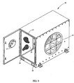
- Figure 2 is a side perspective view of the inlet cabinet of Figure 1;
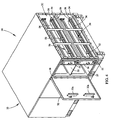
- Figure 3 is side perspective view of the interior of the inlet cabinet of Figure 2;
- Figure 4 is a side perspective view of the second filtering cabinet of Figure 1;
- Figure 5 is a perspective view of the filtering cabinet of Figure 4 depicting the retrieval rod
- Figure 6 is perspective view of the interior of a compartment of the filtering cabinet of Figure 4 with a secondary filter therein;
- Figure 7 is a side perspective view of a filter clamp assembly of the present invention.
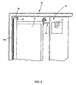
- Figure 8 is a side perspective view of the filter clamp assembly of Figure 7 disposed in another position adjacent the secondary filter;
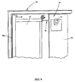
- Figure 9 is a side perspective view of the filter clamp assembly of Figure 7 disposed in yet another position adjacent the secondary filter
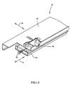
- Figure 10 is a top perspective view of the filter clamp assembly of Figure 7 removed from the filtering cabinet and shown in a first position;
- Figure 11 is a top perspective view of the filtering clamp of Figure 10 shown in a second position
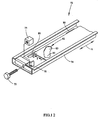
- Figure 12 is a top perspective of the slide with clamp removed for clarity
- Figure 13 is a side perspective view of the clamp assembly
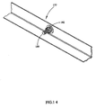
- Figure 14 is an angle with cupped washers for use with a third stage HEPA filter
- Figure 15 is a side perspective view of the interior of the third fan cabinet of Figure 1 with the integrated jib of the present invention
- Figure 16 is a lower perspective view of the integrated jib of Figure 15;
- Figure 17 is a side perspective view of the integrated jib extending through a first jib retainer in the fan cabinet of Figure 15;
- Figure 18 is a side perspective view of the integrated jib positioned in a second jib retainer of the third cabinet housing;
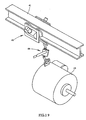
- Figure 19 is a side perspective view of the integrated jib with trolley and hoist mounted thereto.
- Figure 20 is a side perspective view of an alternative embodiment of the present invention utilizing a vertical filtering system.
- a filter clamping assembly filtering apparatus for removing harmful nuclear, biological, chemical, or other particulate from an air supply where zero bypass of at least one filter is a necessity.
- the present invention provides an integrated jib for a fan housing cabinet.
- the present invention comprises a filter retrieval apparatus.
- the multi-stage filtering apparatus 10 is depicted including a multiple cabinet system for filtration. More specifically, according to the illustrative embodiment shown, the filtering apparatus 10 comprises a three cabinet system including a inlet cabinet 20, a filtration cabinet 30, and a fan-housing cabinet 40 may be horizontally oriented, as described herein, or a vertically oriented multi-stage filtering apparatus 110, as shown in Figure 20.
- orientation of the filtering apparatus 10 is defined with respect to the movement of airflow through the filtration apparatus 10.
- Horizontal orientation of the filtering apparatus 10 means that the direction of airflow through the cabinets is substantially horizontal, while vertical orientation of the filtering apparatus is defined by vertical airflow through the filtering apparatus.
- the apparatus may be vertically oriented as shown in Figure 20 by multi-stage filter apparatus 110.
- the system may be designed for various CFM ratings and may further include a cooing system such as a chilled water cooling system or a direct expansion cooling system.
- the exemplary filtering apparatus 10 includes three cabinets; however various designs may include any number of cabinets.
- the first cabinet 20 provides an air inlet for the filtering apparatus 10 while the second cabinet 30 provides a filtration function.
- the third cabinet 40 provides a housing for a fan generally indicated by 42 and motor 43 ( Figure 15) therein for providing a negative pressure upstream of the third cabinet 40 through the inlet cabinet 20 and the filtration cabinet 30.
- the fan-housing cabinet may be operatively positioned upstream of the filtration cabinet 30 thereby placing a positive pressure on the filtration cabinet 30.
- the filtering apparatus 10 may be positioned, for instance, adjacent a sorting machine (not shown) in order to filter air particulate generated within the sorter.
- the inlet cabinet 20 is shown in a side perspective view generally having an upper surface, a lower surface and four side surfaces defining the inlet cabinet or enclosure having an inlet 12 and outlet 19. At least one side including the air inlet 12 has a safety grating 14 applied over the air inlet 12.
- the air inlet 12 is shown as circular in shape and may be of varying diameter depending on the amount of airflow being pulled through the system 10. However, the shape of the inlet 12 may comprise alternate geometric configurations. Due to the size of the inlet 12 in large applications the safety grating 14 may be positioned at the inlet 12 to inhibit workers from falling into the inlet cabinet 10 during operation of the filtration assembly.
- a door 16 is included on the cabinet to access the interior portion thereof including a viewing port 17 allowing postal workers to view the interior of the inlet cabinet during operation to check for debris and material therein.
- the viewing port 17 is substantially circular in shape, but may include various geometries, and is disposed normal to the flow of air through the inlet cabinet 20 so that workers may view any debris entrained in the airflow passing through the cabinet 20 and make a determination when cleaning of the inlet cabinet 20 is necessary.
- at the bottom of the cabinet are forklift pockets 18 which allow for use of a forklift in moving and placing the inlet cabinet 20 adjacent the filtration cabinet.
- the forklift pockets 18 are used in each of the inlet cabinet 20, filtration cabinet 30, and fan housing or cabinet 40.
- the cabinets 20, 30 and 40 may not be limited to utilization of forklift pockets but instead may comprise a variety of legs or other support structures and designs.
- FIG. 3 an interior view of the inlet cabinet 20 is shown with the cabinet door 16 ajar revealing the interior of the viewing port 17.
- a small mesh screen 19 Opposite the air inlet 12 is a small mesh screen 19 having two functions. First, the screen or mesh 19 is utilized to diffuse air flow moving from the inlet cabinet 20 to the filtration cabinet. Second the mesh screen 19 serves to remove large particles and debris from entrainment thus preventing such particulate from entering the filtration cabinet 30. Thus the screen mesh 19 is fastened against an inlet side of the filtration cabinet 30 by a connecting flange or other fastener assembly.
- the inlet cabinet utilizes a knife edge seal 13 around the door opening so that the seal is engaged when the door is closed.
- the knife edge seal 13 provides a high integrity seal between the door opening and the door of the inlet cabinet.
- Such knife edge seal is also utilized on the filtration cabinet 30.
- a switch 15 is positioned which may be in electrical communication with the computer or other safety device to indicate to an operator that the inlet cabinet door has been opened. This switch 15 may be in electrical communication with a circuit to inhibit operation of the filtration apparatus 10 when a door to a cabinet is open.
- the filtration cabinet 30 is defined by a top surface, a lower surface, and a plurality of sides wherein at least one of the sides defines an inlet 31 and an opposite side defines an outlet 33.
- the filtration cabinet 30 is shown including at least one cabinet door 32, and preferably three doors, one of which is depicted in the open position adjacent the inlet portion of the filtration cabinet 30.
- the inlet opening 31, at the right hand end of the cabinet 30 is abutted to the inlet cabinet screen 19 ( Figure 3) and connected by, for instance, flanged connection shown utilizing a plurality of bolt apertures.
- first filter tracks 34 Within the first door 32 of the filtration cabinet 30 are two filter tracks 34, 35 shown separated by a vertical support 36 extending from the upper portion of the filtration cabinet 30 to a lower portion of the filtration cabinet 30 and which are located at the top and bottom of the cabinet 30. Adjacent the cabinet inlet 31 at upper and lower positions are the first tracks 34 which receive, for instance, a 4" pleated filter known in the art as a prefilter, or first-stage filter.
- the first tracks 34 have an open end proximate the door 32 for slidably positioning of a filter and the first tracks 34 include an upper filter track and a lower filter track which extend across the depth of the filtration cabinet from adjacent the door 32 of the cabinet 30 to the opposed wall of the cabinet 30, each first track 34 accepting a first-stage filter.
- the pleated first-stage filter may be a 30 % efficient dust spot filter.
- the filter retrieval apparatus 50 comprises a plurality of rod supports 52 extending vertically adjacent portions of the upper and lower tracks 34.
- the rod supports 52 may be formed of various materials including for instance, steel or other metals, and have a retrieval rod or bar 54 extending laterally through the rod supports 52 and slidably disposed therein from the door side of the cabinet 30 to the opposed wall of the filtration cabinet 30.
- the rod supports 52 are designed to inhibit interference with the first-stage filter during installation and removal which is very important for maintenance as well as inhibiting damage to the filter or performance thereof.
- a ring or pull 55 for grasping and pulling the rod 54 laterally through the rod supports 52.
- a metal finger 56 is located which is positioned between a first-stage filter (not shown) and the cabinet sidewall opposite the door 32.
- the finger 56 moves laterally toward open end of the tracks 34.
- the filters are moved toward the open end of tracks 34.
- the first-stage filters are removed from the filtration cabinet first tracks 34, for example, for cleaning or replacement
- the rod 54 may be pushed into the cabinet 30 in order to accept new or cleaned filters in the first tracks 34a,34b. This assembly may be utilized for both the upper and lower first track portions 34.
- the second-stage tracks 35 may be for example about 12" wide and may therefore fit a filter 37 having a width of about 12", although this dimensional description is exemplary and the dimensions may change.
- the exemplary filters 37 may be 90-95% dust spot efficient and may be pleated utilizing a single header meaning the filters utilize a metal, plastic, or other synthetic framing 38 extending about one side of the second-stage filter 37.
- a single header filter 37 is being installed in the unit with the header 38 adjacent the rear portion of the cabinet 30.
- the filter 37 may also comprise a gasket 38 a extending along one side of the filter 37, preferably adjacent the cabinet 30.
- a header channel 33 is formed in each of the upper and lower second-stage tracks 35.
- the header channel 33 is shown defined by the cabinet 30 and at least one metal member 39 depending from the ceiling of the filtration cabinet 30 wherein a slot is formed for receiving the header 38.
- the member 39 inhibits tilting of the filter 37 in a clockwise direction, as shown in Figure 7 when the second-stage filter 37 is initially installed. With the filter 37 and header 38 disposed in a substantially vertical position, the second-stage filter 37 is ready for sealing against the cabinet 30 in order to inhibit air leakage around the filter 37.
- the header channel 33 therefore aids in installation of the second-stage filters 37 as well as positioning of the filters in order to clamp the filters in place.
- a second-stage filter retrieval system 60 comprising a slide rod 62 upon which a sled 64 is slidably disposed.
- the slide rod 62 is may be some known structural shape such as for example a square tube and is generally formed of heavier gauge and stronger than the previously described first-stage retrieval rod 54 because the second-stage filter 37 generally is larger and heavier than the first-stage filter.
- the slide rod 62 extends between the vertical support 36 and an opposed cabinet sidewall.
- the sled 64 includes at least one finger 66 which is normally disposed opposite the door 32 between the cabinet 30 sidewall and the at least one second-stage filter 37.
- the second-stage filter retrieval system 60 further utilizes is a sled pull 68 which functions similarly to the first-stage retrieval bar 54 previously described and extends substantially parallel to the slide rod 62.
- the sled pull 68 includes a handle 65 at an end of the sled pull 68 proximate the door 32.
- the handle 65 is pulled by a user, the at least one finger 66 begins moving with the sled 64 along the slide rod 62 toward the door 32.
- the filters 37 positioned on the second-stage track 35 are slidably removed from the cabinet 30.
- the handle 65 is shown disposed against the vertical support 36 by utilizing a notched portion in the vertical support 36.
- the notched portion allows for proper positioning of the handle 65 thereby inhibiting interference between the second-stage retrieval handle 65 and the door 32 of the filtration cabinet 30 when the door 32 is closed.
- the Figures further depict a filter locator 32a utilized for proper positioning of the first-stage filter upon closing of the filtration cabinet door 32. The locator 32a engages the first-stage filter upon closing of the door to ensure that the filters are properly seated for filtering.
- a drive assembly sealing mechanism or clamp assembly 70 is shown for positively sealing the second-stage filter 37 against the cabinet 30.
- a seal is created between the second-stage filter 37 and the cabinet 30 to inhibit leakage by positioning a sealing gasket there between.
- the second-stage filter 37 utilizes the gasket material 38a along the header 38 which engages the inner structure of the filtration cabinet 30 to provide a proper seal and forces airflow through the second-stage filter 37.
- the drive assembly sealing mechanism 70 has been developed for use in the present filtration assembly 10.
- the drive assembly sealing mechanism 70 functions to convert rotational movement of at least one bolt 72, into a first horizontal movement of a slide 74 and a second horizontal movement including a net movement perpendicular to the first horizontal movement in order to move a clamp 76, and engage the second-stage filter 37.
- the at least one bolt 72 is positioned through the vertical support 36.
- a clamp assembly 70 is utilized along the upper and lower edges of each filter 37 in order to place a force along upper and lower edges of the second-stage filter 37.
- one bolt 72 is utilized with each clamp assembly 72 for example, the one bolt 72 is located at the top of the vertical support 36 to engage the upper edge of the filter 37, a second bolt is located adjacent the bottom portion second-stage filter 37.
- a third bolt is located beneath the second bolt for engaging the upper portion of the lower second-stage filter and a fourth bolt, which is not shown, is located at the bottom of the vertical beam to engage a lower portion of the lower second-stage filter.
- the at least one bolt 72 is rotated in the clockwise direction, in order to cause the clamp 76 to engage the filter 37. Further rotation moves the filter 37 toward the cabinet sidewall causing engagement between the gasket and cabinet 30 sidewall. Further rotation in the clockwise direction causes sealing engagement between the filter gasket, filter, and cabinet 30.
- Figures 7-9 depict the clamp 76 moving toward and engaging the filter 37 and bolt 72 is rotated.
- the clamp assembly 70 comprises two main parts: a slide 74 having adjustment bolt 72 extending therefrom and the clamp 76 positioned on an upper surface of the slide 74 and moving relative to the slide 74 during rotation of the bolt.
- the clamp 76 is shown in a forward-most position as the clamp 76 would be positioned when engaging the filter 37 in a sealing engagement.
- Figure 11 shows the clamp 76 positioned as it would be if fully moved away from the filter 37.
- the clamp moves in two directions within a horizontal plane as indicated by the arrows shown in Figure 11. The net translation of the clamp 76 is movement toward the second-stage filter 37.
- the slide 74 is shown with the clamp 726 removed and exposing the interior portions of the slide 74.
- the slide 74 of the exemplary embodiment is generally channel shaped.
- At one end of the slide 74 is the adjustment bolt 72 extending through an aperture in the slide 74.
- On a backside of the bolt aperture is a brass retainer 75 shown in exploded fashion in Figure 12.
- the retainer 75 includes at least one helical thread extending there through.
- the retainer 75 is captured within a retainer pocket 78 inhibiting rotation of the retainer 75 when the bolt 72 turns.
- the bolt 72 On a rearside of the vertical support 36, the bolt 72 includes at least one washer and a lock-nut which retain the bolt 72 in place relative to the cabinet 30.
- the retainer 75 receives the adjustment bolt 72 but the retainer 75 cannot rotate.
- the rotation of the bolt 72 is translated to the slide 74 in the formed of linear motion along the axis of the bolt 72 due to the engagement between the bolt threads and the retainer threads 75 and the slide 74.
- the slide 74 comprises at least one slot 80 to guide the slide in a first direction as indicated by the arrow.
- the at least one slot 80 functions to guide the slide during linear motion created by rotation of the bolt 72.
- the at least one slot 80 allows linear movement of the slide 74 when the bolt 72 is rotated.
- the slide 74 also comprises at least one angled camming slot 82 which functions to convert the linear motion of the slide 74 to a second translational motion for the clamp 76.
- the second translational motion includes movement perpendicular to slide movement "A” causing the clamp 76 to engage the filter 37 and provide a sealing engagement.
- This perpendicular motion is indicated in Figure 12 as movement "Y”.
- the angled camming slot 82 comprises a first portion 83 and a second portion 85 disposed at an angle to the first portion 83 and within the same horizontal plane.
- the angled camming slot 82 receives a stud 90 depending from the clamp 76.
- the stud 90 may further comprise a friction reducing member such as a linear bearing or the like to reduce friction between the stud 90 and the angled camming surface 82.
- a cut-away view of the clamp assembly 70 is shown revealing the engagement between a stud 90 and the angled camming slot 82.
- the clamp 76 utilizes the studs 90 which may have roller bearings or other friction reduction means sized to fit within the angled camming slot 82.
- the rotational movement of the bolt 72 is translated by the retainer 75 and pocket 78 design into linear movement of the slide 74.
- the stud 90 and clamp 76 disposed within the angled cam slot 82 provides for net translational movement of the clamp 76 in a direction substantially perpendicular to the linear movement of the slide 74.
- This perpendicular movement of the clamp 76 causes engagement between the clamp 76 and the second-stage filter 37 and causes the filter 37 and gasket 38a to engage the cabinet 30. Such engagement provides a tight seal inhibiting air passage around the second-stage filter 37 and provides proper operation of the filtration apparatus.
- a chamfered edge of a lip is shown extending from an upper surface of the clamp 76 near the retrieval rod 54.
- the chamfered edge is formed in such a manner as to inhibit locking or interference with the retrieval rod finger 56 against the lip as would occur if that edge were instead vertical.
- the aforementioned first and second tracks 34, 35 are all disposed within the first section of the filtration cabinet 30 behind the door 32 shown as open in Figures 4-6. Adjacent this first section (to the left) is a second section having a similar door and housing a third filter area or a HEPA filter section for filtering of nuclear, bacterial, viral, or other biological particulate or contaminants from the air system. Accordingly, the HEPA filter utilizes a finer mesh filter in order to screen smaller particles including the aforementioned biological contaminants.
- the HEPA filter section is similar to the second-stage track 35 previously described.
- One substantial difference with the HEPA filter system is that the HEPA header channel is sized so that a worker may not install a second-stage filter in the HEPA filter section or vice-versa.
- a second difference in the HEPA filter section of the filtration cabinet involves the clamping structure which engages the HEPA filter. While light leakage in the first and second-stage portions of the filtration cabinet is undesirable but slightly tolerable, such leakage at the HEPA filter is intolerable during operation. Thus, it is extremely important to insure an equal force is transmitted by the clamp against the edges of the HEPA filter so that proper sealing along the opposed gasket edge of the filter occurs at the cabinet.
- a spring mounted angle iron or other member 177 is positioned along a HEPA clamp 176 to compensate for any differences in force along the linear engagement edge of the clamp 176, thus applying even force across the filter header.
- the clamp 176 is substantially similar to the clamp 76 utilized with the second-stage filter 37.
- the angle iron 177 is positioned along the engagement edge of the clamp 176 of the HEPA filter track providing for engagement between the HEPA filter and angle iron 177.
- the angle iron 177 utilizes a first fastener 179 to connect to the clamp 176 along a lower horizontal portion of the angle iron 177.
- Extending from a second vertical surface of the angle iron 177 is at least one second fastener 180 having at least one elastic member 182 operably engaged therewith.
- the at least one fastener 180 is comprised of a plurality of fasteners 180 spaced apart along the vertical portion of the angle iron 177 reducing point force loading of the angle iron on the HEPA filter and instead providing an equal application of force along the HEPA filter for proper sealing.
- the fan-housing cabinet 40 is depicted comprising an integrated jib 41.
- the fan-housing cabinet 40 comprises a fan 42 and motor 43 for producing airflow through the multi-stage filtering apparatus 10.
- the housing 40 includes upper and lower surfaces and four sides defining the housing 40.
- the integrated jib 41 includes a housing bracket or first jib retainer 44 at a first door opening frame 45 and includes a jib pocket or second jib retainer 46 formed in the opposite wall of the cabinet 40.
- the bracket 44 includes a pin 47 extending downwardly through a beam flange.
- depending from the jib 41 may be a trolley 48 and hoist 49 may be for vertically lifting the fan motor 43 and removing the motor 43 from the housing cabinet 40.
- the bracket 44 is shown in the upper framing of the door opening 45 through which the jib 41 may be slidably disposed. As shown in Figures is formed in the fan housing wall 40 opposite the door and brackets, previously described, to receive the beam so that the beam is supported at one end within a pocket and within a second end by the bracket.
- a pin 47 may be positioned through the jib 41 and bracket in order to lock the beam in position once the jib 41 is disposed across the fan housing 40 and into the jib pocket 46 (Figure 18).
- Figure 19 depicts the trolley 48 and the hoist 49 depending from the jib 41 and engaging the fan motor 43 for lifting the motor and slidably removing the motor 43 from the housing 40.
Landscapes
- Chemical & Material Sciences (AREA)
- Chemical Kinetics & Catalysis (AREA)
- Filtering Of Dispersed Particles In Gases (AREA)
Applications Claiming Priority (1)
| Application Number | Priority Date | Filing Date | Title |
|---|---|---|---|
| US10/895,703 US7332012B2 (en) | 2004-07-21 | 2004-07-21 | Multi-stage filtering apparatus |
Publications (2)
| Publication Number | Publication Date |
|---|---|
| EP1618942A2 true EP1618942A2 (fr) | 2006-01-25 |
| EP1618942A3 EP1618942A3 (fr) | 2006-04-26 |
Family
ID=35004204
Family Applications (1)
| Application Number | Title | Priority Date | Filing Date |
|---|---|---|---|
| EP05015873A Withdrawn EP1618942A3 (fr) | 2004-07-21 | 2005-07-21 | Filtre à plusieurs étages |
Country Status (3)
| Country | Link |
|---|---|
| US (1) | US7332012B2 (fr) |
| EP (1) | EP1618942A3 (fr) |
| CA (1) | CA2512914A1 (fr) |
Families Citing this family (30)
| Publication number | Priority date | Publication date | Assignee | Title |
|---|---|---|---|---|
| KR100926761B1 (ko) * | 2002-12-23 | 2009-11-16 | 삼성전자주식회사 | 공기청정기 |
| SE525402C2 (sv) * | 2003-06-19 | 2005-02-15 | Tetra Laval Holdings & Finance | Anordning och förfarande för fasthållning av en strålkälla |
| US7588618B2 (en) * | 2006-01-20 | 2009-09-15 | Aaf-Mcquay Inc. | Filter cassette rack |
| US7905947B2 (en) * | 2006-05-24 | 2011-03-15 | L.C. Eldridge Sales Co., Ltd. | Method and apparatus for removing contaminates from air |
| USD575382S1 (en) * | 2007-04-19 | 2008-08-19 | Frank Hammes | Air flow cabinet |
| US8105409B2 (en) * | 2009-01-30 | 2012-01-31 | General Electric Company | Filter retention system |
| US8052770B2 (en) * | 2009-03-13 | 2011-11-08 | General Electric Company | Filter retainer for turbine engine |
| US8048186B2 (en) * | 2009-04-02 | 2011-11-01 | General Electric Company | Filter retention systems and devices |
| US20100132320A1 (en) * | 2010-01-27 | 2010-06-03 | Ali Sharifi | Air pollution dry cleaning apparatus |
| US20120131892A1 (en) * | 2010-11-30 | 2012-05-31 | San Ford Machinery Co., Ltd. | Detachable air filter machine |
| US8597391B1 (en) | 2011-04-12 | 2013-12-03 | Osprey, Inc. | Filtration system and method |
| US8679236B1 (en) | 2011-04-12 | 2014-03-25 | Osprey, Inc. | Filtration system and method |
| US8727459B2 (en) * | 2011-07-08 | 2014-05-20 | SSI Schäfer Noell GmbH Lager- und Systemtechnik | Multiple-door switchgear cabinet |
| TWI588419B (zh) * | 2014-03-24 | 2017-06-21 | 台達電子工業股份有限公司 | 分離式模組之空調設備組合 |
| US9441583B2 (en) * | 2014-06-03 | 2016-09-13 | Caterpillar Inc. | Air filter assembly for a machine |
| CN109154451B (zh) | 2016-03-10 | 2021-11-26 | 开利公司 | 空气处理单元 |
| US10119469B2 (en) | 2016-09-15 | 2018-11-06 | General Electric Company | Method and apparatus for modularized inlet silencer baffles |
| US10722990B2 (en) | 2016-09-15 | 2020-07-28 | General Electric Company | Method for installing and removing modularized silencer baffles |
| CN108278157B (zh) | 2017-01-06 | 2022-08-02 | 通用电气公司 | 用于改进的入口消音挡板的系统和方法 |
| CN108278158B (zh) | 2017-01-06 | 2022-05-13 | 通用电气公司 | 用于改进的入口消音挡板的系统和方法 |
| US11098911B2 (en) * | 2017-06-21 | 2021-08-24 | Air Distribution Technologies Ip, Llc | HVAC scrubber unit with building management system integration systems and methods |
| US10808950B2 (en) * | 2018-03-12 | 2020-10-20 | Johnson Controls Technology Company | Filter track assembly for HVAC units |
| US11291340B2 (en) * | 2019-03-01 | 2022-04-05 | Troy Taylor | Paint booth filter |
| DE102020110081B4 (de) | 2020-04-09 | 2025-06-26 | Lufttechnik Gransee GmbH | Filtervorrichtung |
| DE102020110082A1 (de) * | 2020-04-09 | 2021-10-14 | Lufttechnik Gransee GmbH | Filtervorrichtung und Verfahren zum Wechseln eines Filterelementes |
| CN111379748B (zh) * | 2020-04-10 | 2021-06-22 | 台州市杰龙风机厂 | 一种排尘风机用具有过滤机构的弯管机构 |
| EP4162154B1 (fr) * | 2020-06-05 | 2025-06-04 | Donaldson Company, Inc. | Système de serrage et agencement de filtre et procédés |
| US20220265888A1 (en) * | 2021-02-19 | 2022-08-25 | LENS Therapies, LLC | Air purifying device |
| USD1114216S1 (en) * | 2021-12-02 | 2026-02-17 | Lg Electronics Inc. | Ventilation filter |
| CN119612897B (zh) * | 2025-02-06 | 2025-05-09 | 辽宁科技学院 | 一种污泥减量处理装置 |
Family Cites Families (50)
| Publication number | Priority date | Publication date | Assignee | Title |
|---|---|---|---|---|
| US3350862A (en) * | 1965-07-22 | 1967-11-07 | American Air Filter Co | Modular support frame and filter media assembly |
| US3434269A (en) | 1967-08-09 | 1969-03-25 | American Air Filter Co | Filter cell retaining apparatus |
| FR1550446A (fr) | 1967-11-10 | 1968-12-20 | ||
| US3581476A (en) | 1968-09-10 | 1971-06-01 | American Air Filter Co | Fluid-treating cartridge construction |
| US3626668A (en) | 1969-05-19 | 1971-12-14 | George H Cardiff | Electronic air filter means |
| US3593503A (en) | 1969-05-27 | 1971-07-20 | Mine Safety Appliances Co | Side-loading filtering apparatus |
| US3630008A (en) * | 1969-10-23 | 1971-12-28 | American Air Filter Co | Filter cell sealing and retaining arrangement |
| US3693328A (en) | 1970-05-04 | 1972-09-26 | Farr Co | Filter apparatus with removable filter elements |
| IT940422B (it) | 1970-06-12 | 1973-02-10 | Mikropul Gmbh | Dispositivo per filtrare polveri |
| US3740934A (en) | 1971-07-30 | 1973-06-26 | American Air Filter Co | Air filtering unit including a clamping assembly |
| US3816984A (en) | 1972-12-29 | 1974-06-18 | Delbag Luftfilter Gmbh | Air filter housing for filtering suspended substances |
| US3789589A (en) | 1973-02-28 | 1974-02-05 | Res Prod Corp | High performance filter assembly |
| US3993464A (en) | 1973-04-13 | 1976-11-23 | Anf Frangeco S.A. | Air filter |
| US3999969A (en) | 1975-07-21 | 1976-12-28 | American Air Filter Company, Inc. | Air filtering unit |
| US4023944A (en) * | 1976-04-22 | 1977-05-17 | General Electric Company | Filter unit |
| SE403440B (sv) | 1977-01-05 | 1978-08-21 | Svenska Flaektfabriken Ab | Anordning for inspenning av ett kassettfilter i ett filterhus |
| US4124361A (en) * | 1977-05-11 | 1978-11-07 | American Air Filter Company, Inc. | Sealing device for filter cells |
| US4217122A (en) * | 1978-11-01 | 1980-08-12 | American Air Filter Company, Inc. | Filter retaining latch |
| US4251245A (en) | 1979-12-12 | 1981-02-17 | Mine Safety Appliances Company | Side loading filter apparatus |
| US4266956A (en) | 1979-12-26 | 1981-05-12 | American Air Filter Company, Inc. | Filter clamping device |
| NL8102505A (nl) | 1981-05-21 | 1982-12-16 | Swaay Installaties B V Van | Filterkast voor een luchtbehandelingssysteem. |
| US4457336A (en) | 1982-07-14 | 1984-07-03 | Flanders Filters, Inc. | Air flow control apparatus |
| US4498914A (en) | 1983-03-03 | 1985-02-12 | Donaldson Company, Inc. | Filter apparatus including apparatus for clamping an air filter element in a filter housing |
| US4521234A (en) | 1983-07-19 | 1985-06-04 | Flanders Filters,Inc. | Housing for high efficiency particulate air filters |
| DE3502971A1 (de) | 1985-01-30 | 1986-05-07 | Johann Baptist Rombach Gmbh & Co Kg, 7500 Karlsruhe | Filter zur reinigung stroemender gase |
| US4983190A (en) | 1985-05-21 | 1991-01-08 | Pall Corporation | Pressure-swing adsorption system and method for NBC collective protection |
| US4790865A (en) | 1986-05-30 | 1988-12-13 | Demarco Thomas | Two compartment industrial dust collector |
| US4701196A (en) | 1986-09-15 | 1987-10-20 | Research Products Corporation | Air filter assembly |
| US4773922A (en) | 1987-07-22 | 1988-09-27 | The United States Of America As Represented By The United States Department Of Energy | Remotely serviced filter and housing |
| US4822386A (en) | 1987-11-27 | 1989-04-18 | United Technologies Corporation | Filter replacement mechanism |
| US4827901A (en) | 1988-02-19 | 1989-05-09 | Jackson Jerry D | Filter base for forced air furnace |
| US5593470A (en) | 1990-11-14 | 1997-01-14 | Abatement Technologies, Inc. | Portable filtration unit |
| GB9105552D0 (en) | 1991-03-15 | 1991-05-01 | Technivac Ltd | Mobile separation unit |
| US5332409A (en) * | 1993-03-29 | 1994-07-26 | A. J. Dralle, Inc. | Air filtration system |
| US5447544A (en) | 1993-11-17 | 1995-09-05 | Air Engineers, Inc. | Air filtering apparatus |
| US5464461A (en) * | 1993-12-01 | 1995-11-07 | Electronic Cable Specialists, Inc. | Filter for mounting on an avionic line replaceable unit |
| US5399180A (en) * | 1993-12-06 | 1995-03-21 | Kopp; John G. | Modular filter assembly |
| US5549723A (en) * | 1994-08-31 | 1996-08-27 | Terry; Daniel J. | Filter cap |
| US5637124A (en) | 1995-03-23 | 1997-06-10 | Helical Dynamics, Inc. | Modular air cleaning system |
| US5665145A (en) | 1995-10-26 | 1997-09-09 | American Standard Inc. | Air filter channel and puller |
| US6063151A (en) | 1998-06-12 | 2000-05-16 | The Spencer Turbine Company | Mobile apparatus and method for clearing gas lines |
| US6174343B1 (en) * | 1999-06-29 | 2001-01-16 | Siemens Canada Limited Ontario | Cam action attachment and locking mechanism for air cleaner shells |
| US6431805B2 (en) | 1999-08-20 | 2002-08-13 | Francis E. Lanciaux, Jr. | Attachable frame for lifting and moving a container |
| US6264713B1 (en) * | 1999-12-02 | 2001-07-24 | Skuttle Manufacturing Company | Media filter assembly having replaceable filter element |
| US6569217B1 (en) | 2000-05-10 | 2003-05-27 | Thomas M. DeMarco | Industrial dust collector with multiple filter compartments |
| US6298672B1 (en) | 2000-08-01 | 2001-10-09 | Robert Valicoff, Jr. | Produce merchandiser |
| US20020072020A1 (en) | 2000-10-16 | 2002-06-13 | Crane John J. | Regnerative burner |
| US6716267B2 (en) * | 2001-10-18 | 2004-04-06 | American Standard International Inc. | Multi-position, spring loaded filter rack |
| DE20216638U1 (de) | 2002-10-28 | 2003-03-06 | Glatter, Ulrich, 36325 Feldatal | Ladekran |
| US6974491B1 (en) * | 2003-08-01 | 2005-12-13 | Kendall Stephen P | Cartridge locking device and method |
-
2004
- 2004-07-21 US US10/895,703 patent/US7332012B2/en not_active Expired - Lifetime
-
2005
- 2005-07-21 CA CA002512914A patent/CA2512914A1/fr not_active Abandoned
- 2005-07-21 EP EP05015873A patent/EP1618942A3/fr not_active Withdrawn
Also Published As
| Publication number | Publication date |
|---|---|
| US7332012B2 (en) | 2008-02-19 |
| CA2512914A1 (fr) | 2006-01-21 |
| US20060016163A1 (en) | 2006-01-26 |
| EP1618942A3 (fr) | 2006-04-26 |
Similar Documents
| Publication | Publication Date | Title |
|---|---|---|
| US7332012B2 (en) | Multi-stage filtering apparatus | |
| US6280507B1 (en) | Air manager apparatus and method for exhausted equipment and systems, and exhaust and airflow management in a semiconductor manufacturing facility | |
| JP6591577B2 (ja) | 水分及び粉塵を除去するためのルーバー装置 | |
| US8747505B2 (en) | V-bank air filtration system such as for animal confinement | |
| RU2660135C2 (ru) | Всасывающая воздух стенка для оснащения промышленных рабочих зон, таких как зоны сварки | |
| CA2016596A1 (fr) | Filtre a air avec elements filtrants horizontaux | |
| US10357736B2 (en) | Downdraft table with self-closing louvre | |
| EP3189283B1 (fr) | Logement de filtre | |
| US7972401B2 (en) | Air intake filter assembly | |
| US20120291406A1 (en) | V-Bank Air Filtration System Such as for Animal Confinement | |
| US20070199289A1 (en) | Filter Holding Frame with Clamping Mechanism | |
| JPS58501575A (ja) | 簡潔なダスト・フイルタ・アセンブリ | |
| MX2012008916A (es) | Soporte de filtros para el acomodo de una diversidad de tamaños de filtros. | |
| JPS6051370B2 (ja) | フイルタ・ユニツト | |
| EP3881923B1 (fr) | Séparateur d'aérosol, ainsi que procédé d'installation d'un élément de filtre à coalescence dans un séparateur d'aérosol | |
| KR20080100345A (ko) | 휴대용 공기 처리 시스템을 위한 필터 보유기 기구 | |
| US6974491B1 (en) | Cartridge locking device and method | |
| JPS63194140A (ja) | 空気調和機の吸込ダクト装置 | |
| US20080113598A1 (en) | Blower enclosure | |
| KR20200117462A (ko) | 공기조화기의 필터박스 | |
| US9812229B2 (en) | Safe geometry vacuum design | |
| KR102200729B1 (ko) | 처짐 방지 기능을 갖는 창문 설치형 하이브리드 공기청정 환기 시스템 | |
| KR101448422B1 (ko) | 여과면적을 높인 흡착탑용 프리필터의 설치구조 | |
| EP2839220B1 (fr) | Hotte de cuisine avec un filtre anti-odeur | |
| AU2013273665A1 (en) | Filter device and filtration system comprised thereof |
Legal Events
| Date | Code | Title | Description |
|---|---|---|---|
| PUAI | Public reference made under article 153(3) epc to a published international application that has entered the european phase |
Free format text: ORIGINAL CODE: 0009012 |
|
| AK | Designated contracting states |
Kind code of ref document: A2 Designated state(s): AT BE BG CH CY CZ DE DK EE ES FI FR GB GR HU IE IS IT LI LT LU LV MC NL PL PT RO SE SI SK TR |
|
| AX | Request for extension of the european patent |
Extension state: AL BA HR MK YU |
|
| PUAL | Search report despatched |
Free format text: ORIGINAL CODE: 0009013 |
|
| AK | Designated contracting states |
Kind code of ref document: A3 Designated state(s): AT BE BG CH CY CZ DE DK EE ES FI FR GB GR HU IE IS IT LI LT LU LV MC NL PL PT RO SE SI SK TR |
|
| AX | Request for extension of the european patent |
Extension state: AL BA HR MK YU |
|
| 17P | Request for examination filed |
Effective date: 20060905 |
|
| 17Q | First examination report despatched |
Effective date: 20061010 |
|
| AKX | Designation fees paid |
Designated state(s): AT BE BG CH CY CZ DE DK EE ES FI FR GB GR HU IE IS IT LI LT LU LV MC NL PL PT RO SE SI SK TR |
|
| STAA | Information on the status of an ep patent application or granted ep patent |
Free format text: STATUS: THE APPLICATION IS DEEMED TO BE WITHDRAWN |
|
| 18D | Application deemed to be withdrawn |
Effective date: 20070421 |