EP1618960A1 - Dispositif et procédé de séparation des particules solides plongeantes et flottantes à densités différentes - Google Patents
Dispositif et procédé de séparation des particules solides plongeantes et flottantes à densités différentes Download PDFInfo
- Publication number
- EP1618960A1 EP1618960A1 EP20040017065 EP04017065A EP1618960A1 EP 1618960 A1 EP1618960 A1 EP 1618960A1 EP 20040017065 EP20040017065 EP 20040017065 EP 04017065 A EP04017065 A EP 04017065A EP 1618960 A1 EP1618960 A1 EP 1618960A1
- Authority
- EP
- European Patent Office
- Prior art keywords
- particles
- solid particles
- channel
- separation
- collecting head
- Prior art date
- Legal status (The legal status is an assumption and is not a legal conclusion. Google has not performed a legal analysis and makes no representation as to the accuracy of the status listed.)
- Granted
Links
- 238000000926 separation method Methods 0.000 title claims abstract description 98
- 239000002245 particle Substances 0.000 title claims abstract description 80
- 239000007787 solid Substances 0.000 title claims abstract description 59
- 238000000034 method Methods 0.000 title claims description 16
- 239000000725 suspension Substances 0.000 claims abstract description 34
- 238000007599 discharging Methods 0.000 claims abstract description 8
- 238000002156 mixing Methods 0.000 claims description 17
- 239000003795 chemical substances by application Substances 0.000 claims description 16
- 238000007872 degassing Methods 0.000 claims description 13
- 239000004033 plastic Substances 0.000 claims description 13
- 229920003023 plastic Polymers 0.000 claims description 13
- 230000005284 excitation Effects 0.000 claims description 9
- 239000008187 granular material Substances 0.000 claims description 4
- 239000013618 particulate matter Substances 0.000 claims description 4
- 229920000098 polyolefin Polymers 0.000 claims 2
- 239000012530 fluid Substances 0.000 abstract 7
- 238000006124 Pilkington process Methods 0.000 abstract 1
- 230000000694 effects Effects 0.000 description 12
- 239000007789 gas Substances 0.000 description 5
- 230000005484 gravity Effects 0.000 description 5
- 238000004064 recycling Methods 0.000 description 5
- XEKOWRVHYACXOJ-UHFFFAOYSA-N Ethyl acetate Chemical compound CCOC(C)=O XEKOWRVHYACXOJ-UHFFFAOYSA-N 0.000 description 3
- 230000007423 decrease Effects 0.000 description 3
- 230000003247 decreasing effect Effects 0.000 description 3
- 238000009826 distribution Methods 0.000 description 3
- -1 polyethylene Polymers 0.000 description 3
- 230000000630 rising effect Effects 0.000 description 3
- XEEYBQQBJWHFJM-UHFFFAOYSA-N Iron Chemical compound [Fe] XEEYBQQBJWHFJM-UHFFFAOYSA-N 0.000 description 2
- 239000004698 Polyethylene Substances 0.000 description 2
- 239000004743 Polypropylene Substances 0.000 description 2
- 230000015572 biosynthetic process Effects 0.000 description 2
- 239000007788 liquid Substances 0.000 description 2
- 239000000463 material Substances 0.000 description 2
- 239000002184 metal Substances 0.000 description 2
- 229910052751 metal Inorganic materials 0.000 description 2
- 239000000203 mixture Substances 0.000 description 2
- 239000004800 polyvinyl chloride Substances 0.000 description 2
- 229920000915 polyvinyl chloride Polymers 0.000 description 2
- 238000003756 stirring Methods 0.000 description 2
- XLYOFNOQVPJJNP-UHFFFAOYSA-N water Substances O XLYOFNOQVPJJNP-UHFFFAOYSA-N 0.000 description 2
- ZAMOUSCENKQFHK-UHFFFAOYSA-N Chlorine atom Chemical compound [Cl] ZAMOUSCENKQFHK-UHFFFAOYSA-N 0.000 description 1
- LFQSCWFLJHTTHZ-UHFFFAOYSA-N Ethanol Chemical compound CCO LFQSCWFLJHTTHZ-UHFFFAOYSA-N 0.000 description 1
- 229920000426 Microplastic Polymers 0.000 description 1
- 239000004952 Polyamide Substances 0.000 description 1
- 230000001174 ascending effect Effects 0.000 description 1
- 229910052801 chlorine Inorganic materials 0.000 description 1
- 239000000460 chlorine Substances 0.000 description 1
- 238000004140 cleaning Methods 0.000 description 1
- 239000000356 contaminant Substances 0.000 description 1
- 230000001419 dependent effect Effects 0.000 description 1
- 238000010586 diagram Methods 0.000 description 1
- 229920001971 elastomer Polymers 0.000 description 1
- 229920006351 engineering plastic Polymers 0.000 description 1
- 238000002474 experimental method Methods 0.000 description 1
- 239000000835 fiber Substances 0.000 description 1
- 238000011049 filling Methods 0.000 description 1
- 238000002309 gasification Methods 0.000 description 1
- 238000000227 grinding Methods 0.000 description 1
- 239000012535 impurity Substances 0.000 description 1
- 239000011261 inert gas Substances 0.000 description 1
- 238000002347 injection Methods 0.000 description 1
- 239000007924 injection Substances 0.000 description 1
- 229910052742 iron Inorganic materials 0.000 description 1
- 238000011068 loading method Methods 0.000 description 1
- 238000002844 melting Methods 0.000 description 1
- 230000008018 melting Effects 0.000 description 1
- 238000003801 milling Methods 0.000 description 1
- 238000005457 optimization Methods 0.000 description 1
- 239000010893 paper waste Substances 0.000 description 1
- 229920002647 polyamide Polymers 0.000 description 1
- 229920000573 polyethylene Polymers 0.000 description 1
- 229920000139 polyethylene terephthalate Polymers 0.000 description 1
- 239000005020 polyethylene terephthalate Substances 0.000 description 1
- 229920001155 polypropylene Polymers 0.000 description 1
- 238000005086 pumping Methods 0.000 description 1
- 239000005060 rubber Substances 0.000 description 1
- 150000003839 salts Chemical class 0.000 description 1
- 229920006395 saturated elastomer Polymers 0.000 description 1
- 239000013049 sediment Substances 0.000 description 1
- 239000000243 solution Substances 0.000 description 1
- 230000007704 transition Effects 0.000 description 1
- 238000009827 uniform distribution Methods 0.000 description 1
- 238000011144 upstream manufacturing Methods 0.000 description 1
- 238000009736 wetting Methods 0.000 description 1
Images


Classifications
-
- B—PERFORMING OPERATIONS; TRANSPORTING
- B03—SEPARATION OF SOLID MATERIALS USING LIQUIDS OR USING PNEUMATIC TABLES OR JIGS; MAGNETIC OR ELECTROSTATIC SEPARATION OF SOLID MATERIALS FROM SOLID MATERIALS OR FLUIDS; SEPARATION BY HIGH-VOLTAGE ELECTRIC FIELDS
- B03B—SEPARATING SOLID MATERIALS USING LIQUIDS OR USING PNEUMATIC TABLES OR JIGS
- B03B5/00—Washing granular, powdered or lumpy materials; Wet separating
- B03B5/28—Washing granular, powdered or lumpy materials; Wet separating by sink-float separation
-
- B—PERFORMING OPERATIONS; TRANSPORTING
- B03—SEPARATION OF SOLID MATERIALS USING LIQUIDS OR USING PNEUMATIC TABLES OR JIGS; MAGNETIC OR ELECTROSTATIC SEPARATION OF SOLID MATERIALS FROM SOLID MATERIALS OR FLUIDS; SEPARATION BY HIGH-VOLTAGE ELECTRIC FIELDS
- B03B—SEPARATING SOLID MATERIALS USING LIQUIDS OR USING PNEUMATIC TABLES OR JIGS
- B03B11/00—Feed or discharge devices integral with washing or wet-separating equipment
-
- B—PERFORMING OPERATIONS; TRANSPORTING
- B03—SEPARATION OF SOLID MATERIALS USING LIQUIDS OR USING PNEUMATIC TABLES OR JIGS; MAGNETIC OR ELECTROSTATIC SEPARATION OF SOLID MATERIALS FROM SOLID MATERIALS OR FLUIDS; SEPARATION BY HIGH-VOLTAGE ELECTRIC FIELDS
- B03B—SEPARATING SOLID MATERIALS USING LIQUIDS OR USING PNEUMATIC TABLES OR JIGS
- B03B13/00—Control arrangements specially adapted for wet-separating apparatus or for dressing plant, using physical effects
-
- B—PERFORMING OPERATIONS; TRANSPORTING
- B03—SEPARATION OF SOLID MATERIALS USING LIQUIDS OR USING PNEUMATIC TABLES OR JIGS; MAGNETIC OR ELECTROSTATIC SEPARATION OF SOLID MATERIALS FROM SOLID MATERIALS OR FLUIDS; SEPARATION BY HIGH-VOLTAGE ELECTRIC FIELDS
- B03B—SEPARATING SOLID MATERIALS USING LIQUIDS OR USING PNEUMATIC TABLES OR JIGS
- B03B5/00—Washing granular, powdered or lumpy materials; Wet separating
- B03B5/28—Washing granular, powdered or lumpy materials; Wet separating by sink-float separation
- B03B5/30—Washing granular, powdered or lumpy materials; Wet separating by sink-float separation using heavy liquids or suspensions
- B03B5/36—Devices therefor, other than using centrifugal force
-
- B—PERFORMING OPERATIONS; TRANSPORTING
- B29—WORKING OF PLASTICS; WORKING OF SUBSTANCES IN A PLASTIC STATE IN GENERAL
- B29B—PREPARATION OR PRETREATMENT OF THE MATERIAL TO BE SHAPED; MAKING GRANULES OR PREFORMS; RECOVERY OF PLASTICS OR OTHER CONSTITUENTS OF WASTE MATERIAL CONTAINING PLASTICS
- B29B17/00—Recovery of plastics or other constituents of waste material containing plastics
- B29B17/02—Separating plastics from other materials
- B29B2017/0203—Separating plastics from plastics
-
- B—PERFORMING OPERATIONS; TRANSPORTING
- B29—WORKING OF PLASTICS; WORKING OF SUBSTANCES IN A PLASTIC STATE IN GENERAL
- B29B—PREPARATION OR PRETREATMENT OF THE MATERIAL TO BE SHAPED; MAKING GRANULES OR PREFORMS; RECOVERY OF PLASTICS OR OTHER CONSTITUENTS OF WASTE MATERIAL CONTAINING PLASTICS
- B29B17/00—Recovery of plastics or other constituents of waste material containing plastics
- B29B17/02—Separating plastics from other materials
- B29B2017/0213—Specific separating techniques
- B29B2017/0217—Mechanical separating techniques; devices therefor
- B29B2017/0237—Mechanical separating techniques; devices therefor using density difference
- B29B2017/0244—Mechanical separating techniques; devices therefor using density difference in liquids
-
- B—PERFORMING OPERATIONS; TRANSPORTING
- B29—WORKING OF PLASTICS; WORKING OF SUBSTANCES IN A PLASTIC STATE IN GENERAL
- B29K—INDEXING SCHEME ASSOCIATED WITH SUBCLASSES B29B, B29C OR B29D, RELATING TO MOULDING MATERIALS OR TO MATERIALS FOR MOULDS, REINFORCEMENTS, FILLERS OR PREFORMED PARTS, e.g. INSERTS
- B29K2023/00—Use of polyalkenes or derivatives thereof as moulding material
- B29K2023/04—Polymers of ethylene
- B29K2023/06—PE, i.e. polyethylene
-
- B—PERFORMING OPERATIONS; TRANSPORTING
- B29—WORKING OF PLASTICS; WORKING OF SUBSTANCES IN A PLASTIC STATE IN GENERAL
- B29K—INDEXING SCHEME ASSOCIATED WITH SUBCLASSES B29B, B29C OR B29D, RELATING TO MOULDING MATERIALS OR TO MATERIALS FOR MOULDS, REINFORCEMENTS, FILLERS OR PREFORMED PARTS, e.g. INSERTS
- B29K2023/00—Use of polyalkenes or derivatives thereof as moulding material
- B29K2023/10—Polymers of propylene
- B29K2023/12—PP, i.e. polypropylene
-
- B—PERFORMING OPERATIONS; TRANSPORTING
- B29—WORKING OF PLASTICS; WORKING OF SUBSTANCES IN A PLASTIC STATE IN GENERAL
- B29K—INDEXING SCHEME ASSOCIATED WITH SUBCLASSES B29B, B29C OR B29D, RELATING TO MOULDING MATERIALS OR TO MATERIALS FOR MOULDS, REINFORCEMENTS, FILLERS OR PREFORMED PARTS, e.g. INSERTS
- B29K2055/00—Use of specific polymers obtained by polymerisation reactions only involving carbon-to-carbon unsaturated bonds, not provided for in a single one of main groups B29K2023/00 - B29K2049/00, e.g. having a vinyl group, as moulding material
- B29K2055/02—ABS polymers, i.e. acrylonitrile-butadiene-styrene polymers
-
- B—PERFORMING OPERATIONS; TRANSPORTING
- B29—WORKING OF PLASTICS; WORKING OF SUBSTANCES IN A PLASTIC STATE IN GENERAL
- B29K—INDEXING SCHEME ASSOCIATED WITH SUBCLASSES B29B, B29C OR B29D, RELATING TO MOULDING MATERIALS OR TO MATERIALS FOR MOULDS, REINFORCEMENTS, FILLERS OR PREFORMED PARTS, e.g. INSERTS
- B29K2067/00—Use of polyesters or derivatives thereof, as moulding material
-
- Y—GENERAL TAGGING OF NEW TECHNOLOGICAL DEVELOPMENTS; GENERAL TAGGING OF CROSS-SECTIONAL TECHNOLOGIES SPANNING OVER SEVERAL SECTIONS OF THE IPC; TECHNICAL SUBJECTS COVERED BY FORMER USPC CROSS-REFERENCE ART COLLECTIONS [XRACs] AND DIGESTS
- Y02—TECHNOLOGIES OR APPLICATIONS FOR MITIGATION OR ADAPTATION AGAINST CLIMATE CHANGE
- Y02W—CLIMATE CHANGE MITIGATION TECHNOLOGIES RELATED TO WASTEWATER TREATMENT OR WASTE MANAGEMENT
- Y02W30/00—Technologies for solid waste management
- Y02W30/50—Reuse, recycling or recovery technologies
- Y02W30/52—Mechanical processing of waste for the recovery of materials, e.g. crushing, shredding, separation or disassembly
-
- Y—GENERAL TAGGING OF NEW TECHNOLOGICAL DEVELOPMENTS; GENERAL TAGGING OF CROSS-SECTIONAL TECHNOLOGIES SPANNING OVER SEVERAL SECTIONS OF THE IPC; TECHNICAL SUBJECTS COVERED BY FORMER USPC CROSS-REFERENCE ART COLLECTIONS [XRACs] AND DIGESTS
- Y02—TECHNOLOGIES OR APPLICATIONS FOR MITIGATION OR ADAPTATION AGAINST CLIMATE CHANGE
- Y02W—CLIMATE CHANGE MITIGATION TECHNOLOGIES RELATED TO WASTEWATER TREATMENT OR WASTE MANAGEMENT
- Y02W30/00—Technologies for solid waste management
- Y02W30/50—Reuse, recycling or recovery technologies
- Y02W30/62—Plastics recycling; Rubber recycling
Definitions
- the invention relates to a device and a method for the floating-sink separation of solid particles of different density according to the preamble of claim 1 and 12, respectively.
- the swim-sink separation is used for various tasks.
- plastics recycling for example, it serves to separate impurities, such as polyvinyl chloride, which release undesirable chlorine gases during melting or gasification, from unsorted plastics shredded into granules.
- polyethylene regrind is to be separated from polypropylene regrind in order to obtain two synthetically pure as possible with Neuwarencharachter at least for the most important mechanical properties.
- Further fields of application are, for example, the separation of metal and plastic or rubber particles during cable recycling, plastic particles of paper fibers in reject rejection from waste paper recycling and the separation of non-ferrous metals from iron.
- a mixture of solids to be separated is brought into suspension with a separation medium, the density of which is set between the density of the recyclable recyclables and the respective contaminants.
- the mixture separates into a floating light fraction and a heavy fraction which sinks as a result of the action of gravity, which are discharged, optionally dried and then further processed.
- the disadvantage here is that the exit velocity of the suspension must be higher than the sinking rate of the heaviest particulate matter due to the vertically rising feed tube so that they do not sediment back. From this high exit velocity results in a turbulent flow at least in the region of the exit, so that in particular solid particles with a density close to the density of the separation medium as well as small solid particles arrive at random into the floating or sinking fraction stream. A separation is therefore not achievable with acceptable accuracy with the known device.
- the throughput is severely limited by the formation of turbulence at high exit velocities.
- DE 199 81 222 C1 specifies as a suitable diameter of the solid particles the range between about 10 and 50 mm.
- the diameter required for optimal type purity in the recycling of plastics is far below, namely at about 2 to 7 mm, the shredding even up to 15 wt .-% solid particles with a diameter down to 0.5 mm incurred.
- Experiments with plastics typical of motor vehicles have shown that even with a granule diameter of about 7 mm between 20 and 30% solid particles are present in the floating light fraction, which actually belong to the sinking heavy fraction. A high degree of purity and selectivity are therefore not achievable with the device known from DE 199 81 222 C1.
- Another problem is the optimal spacing of the sheets. If the distance is too large, particulate matter with a density close to the density of the separation medium entering the separation space will not arrive in the associated flow half and will be entrained with the wrong flow. However, if the distance is too low, sets a high flow rate, so that the solid particles are entrained in the deflection according to their random distribution after exiting the feed tube and also arise at the transition to the separation space further turbulence that interfere with the formation of the fractions.
- the invention is therefore an object of the invention to provide a device and a method for floating-sink-separating solid particles of different density according to the preamble of claim 1 and 12, which allow for increased throughput a more accurate separation.
- the fractions Due to the oblique channel with a transverse to the longitudinal axis fed suspension, the fractions can each form a laminar flow over a long path away. Turbulences are already in the Reduced feed and the flow is in the inlet region of the channel completely in the laminar state. In the channel, the light and heavy fractions are close to each other, so that solid particles quickly get into the appropriate fraction under the action of gravity.
- a discharge device for discharging a fraction stream the flow rate of the heavy fraction stream in the channel can be set to a desired value and kept constant. It is achieved an optimal separation effect with high throughput.
- the channel thereby provides in each case a separation surface for the ascending and for the sinking solid particles, at which they can slide along the respective collecting head as a result of the low velocities of the separation medium prevailing in the boundary layer.
- the channel acts reassuring on the separation medium, especially at higher flow velocities, i. it reduces turbulence.
- a plurality of channels are formed in the separation space by one or more vertically spaced parallel plates. As a result, the throughput is increased at substantially constant space requirements.
- plates can extend from the separation space into the feed channel for the suspension, in order to counteract turbulence.
- the plates then preferably do not extend more than 1/3 into the feed channel, since otherwise a pre-separation of the solid particles in the distribution channel is prevented.
- a further feed opening for separation medium without solid particles is provided between the feed opening for the suspension and the upper collecting head.
- the amount of suspension M S supplied per unit time and the control quantity M R of pure release agent supplied per unit time are in particular set in the separation space in such a way that the control quantity M R more release agent volume is metered than must flow into the upper collecting head for the light fraction.
- the buoyancy effect by adhering buoyancy elements can also be effectively counteracted in certain areas by setting a differential speed between the upward light fraction stream on the one hand and the downstream heavy fraction stream on the other hand.
- the differential velocity here is the magnitude of the velocity of the sword fraction stream minus the amount of the velocity of the light fraction stream along the channels, respectively.
- the differential speed is preferably set by controlling the delivery rate of a pump for discharging the heavy fraction from the lower collection head and the amount of separation medium supplied to a mixing device per unit time.
- the differential speed is easily and accurately adjustable without the need for complex control.
- the differential speed is preferably controlled by the suspension feed rate. A combination of both control options is possible.
- the differential speed can be set to a value between 0 and 1.5 and preferably between 0 and 0.9 cm per second, so that the floating fraction stream by the set amount floats slower than the decreasing fraction stream decreases.
- plastics with a density greater than 1.24 g / cm 3 of those with densities of less than 1.24 g / cm 3 are most accurately separable.
- the angle ⁇ between the channel and the horizontal is adjustable.
- ⁇ increases, the horizontal velocity component of the flow becomes smaller. Therefore, a correspondingly longer channel distance is required until the solid particles reach the respective channel wall.
- Suitable values for ⁇ are 30 ° ⁇ ⁇ 60 ° and preferably 35 ° ⁇ ⁇ 45 °.
- the buoyancy effect by adhering buoyancy elements can alternatively or additionally be counteracted by at least partial degassing of the separation medium.
- a mixing device in which the solid particles are introduced into the separation medium, upstream of a degassing device.
- the release agent emerging from the degassing device and entering the mixing device is no longer in gas equilibrium and absorbs air adhering to the solid particles up to its gas equilibrium state.
- the buoyancy effect can also be counteracted by vibration excitation of the suspension flow, in particular in the region of the mouth of the feed channel into the separation space, optionally also in the feed channel. Due to the vibrations, the buoyancy elements can be detached from the solid particles.
- the vibration excitation additionally causes adhering solid particles to be separated.
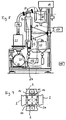
- the illustrated in Fig. 1 to 3 apparatus 1 for sink-float separation comprises a filled with a suspension of solid particles to be separated and a separation medium separating chamber 2 with channels 3, arranged in different heights lower and upper collecting heads 4, 5 for Gravity effect in the channels 3 sunken or floated solid particles open.
- the channels 3 are formed here by four vertically equally spaced parallel plates 6 and side walls 7 of the separation space 2.
- the top and bottom of the plates 6 simultaneously forms an upper or lower wall 8 of the Trennraums 2.
- the distance between two adjacent plates 6 is expediently smaller than the distance between the side walls 7, so that a rectangular cross-section with a large guide surface in each case for the floating and marked in Fig. 3 with a point and the sinking and in FIG. 3 shows solid particles marked with a cross.
- the separation space 2 can also be designed in a tubular manner with a plurality of channels 3, in particular separated by plates 6, cf. 4 and 5.
- the angle ⁇ between the channels 3 and the horizontal is possible here via a height adjustment of one of the two columns supporting the separation space 2, for example by a screw / spindle mechanism, a hydraulic device or the like. continuously or by telescoping telescoping and screwing two concentrically arranged pillar elements.
- a feed opening 9 for the suspension is provided in one of the side walls 7, cf. FIG. 4.
- the suspension can be introduced transversely to the longitudinal axis of the channels 3.
- a particular horizontal feed channel 10 is connected to the feed opening 9, which here has a widening and the flow rate reducing cross-section.
- the feed channel 10 expediently has a length which is not smaller than the vertical diameter of the feed opening 9, cf. Fig. 4, but can be significantly longer, cf. Fig. 5, so that the supplied suspension is as free of turbulence.
- the plates 6 can be interrupted, in particular perforated, for a better distribution of the suspension, and optionally extend into the feed channel 10 to preferably 1/3 of its length.
- the supply channel can receive a number of the flow channels 3 corresponding number of sub-feed channels, so that a simple and uniform distribution of the suspension flow is ensured on the individual flow channels.
- the feed opening 9 is arranged closer to the lower than to the upper collection head 4, 5, so that those solid particles of the heavy fraction which are entrained with the rising light fraction stream, before entry into the upper collection head 4 can get into the sinking heavy fraction stream. If the heavy fraction is the target fraction, the feed opening 9 should be arranged correspondingly closer to the upper collecting head 4.
- a further feed opening can be arranged above the feed opening 9, through which pure release agent is metered into the separation space 2 as a so-called control amount by means of an associated feed channel 11.
- This control amount is preferably adjusted so that the partial stream flowing downwardly thereof has a flow velocity which is greater than the rate of ascent of the heavy solid particles otherwise entrained in the light fraction stream.
- a device 12 for vibration excitation with at least one motor, piezoelectric element or the like. Be provided, the or acting on the plates 6 and / or the side walls 7 of the separation space 2 acting the release agent and the solid particles of the suspension in vibration. If the particles get into vibration nodes of the release agent, the cleaning effect of the vibrations is particularly effective. It depends on the task and the separating good, which vibration exciter and which vibration frequency is used. In the case of a plastic separation mechanical vibration exciters with frequencies in the range between 10,000 and 45,000 min -1 have shown very good effect. In the case of solid particles entrained with buoyant elements, the speed difference between the two partial flows in the channels 3 between 20 and 30% could be reduced while the separation quality remained constant, ie the solids throughput could be correspondingly increased.
- ultrasonic generators can be in the frequency range of 10 to 40 kHz, preferably 15 to 25 kHz cavitation effects not only safely remove air from the solid particles, but also good wetting lighter liquids and fines with lower density.
- the device 12 can be placed on an outer wall of the separation chamber 2, cf. Fig. 1. Alternatively or additionally, the plates 6 can be excited directly to vibrate.
- a laterally to the separation space 2 releasably attachable slot 13 is provided with plate portions 14 which extend into the interior of the separation space 2 and in the like, optionally with a guide groove or the like. provided recesses of the plates 6 engage, see. Fig. 6.
- the plate sections 14 may be perforated.
- the stacked plate sections 14 are rigidly fixed in the edge region, for example by clamping in cross connector, see. Fig. 7.
- the device 12 then expediently comprises an exciter rod 12b, which extends through a central region of the plate sections 14 and is vibrated by an exciter motor 12a. Due to the clamping of the plate sections 14 in the edge region and the vibration excitation in the central region, the plate sections 14 swing membrane-like. The vibrations of the excitation motor 12a are thus transmitted very effectively to the suspension and the particulates therein.
- a means for adjusting the rate of difference between the upwardly directed light fraction stream and the downhill heavy fraction stream cf. Fig. 8. It comprises a pump 15 for discharging the heavy fraction from the lower collecting head 5, a pump 16 for discharging the light fraction from the upper collecting head 4, a pump 17 for feeding the suspension through the supply channel 10 and / or a pump 24, about which the separation space 2 per unit time supplied amount of the suspension is indirectly controlled, but preferably only the pumps 15 and 24, and a pump controller 18th
- the pump controller 18 controls the delivery rate of the pumps 15, 16, 17 and / or 24, depending on the embodiment, such that a differential speed is established between the upward light fraction stream and the downward heavy fraction stream at which the selectivity is optimal.
- the optimum delivery rate is determined empirically.
- Particles to be separated for example plastic granules having a diameter of 0.5 to 50 mm, in particular 1 to 10 mm, preferably 2 to 7 mm, optionally with up to 15 wt .-%, in particular up to 10 wt .-% and preferably to to 5 wt .-% in the crushing process, such as milling or shredding, resulting smaller particles, or Kunststoffolienteilchen or the like. are introduced into a mixing device 20 and mixed there by means of a stirring device 19 with a separation medium to form a suspension.
- water is used as the separation medium at a separation density above 1 g / cm 3 , which is buried in a specific concentration for controlling the density of salt.
- organic liquids with a low flash point can be used as separation medium, for example an alcohol / water solution or pure ethyl acetate at 20 ° C. for the separation of PP / PE because the device can be made gas-tight in a simple manner and there is no risk of ignition in the device.
- the mixing device 20 is also designed gas-tight in this case, optionally applied with an inert gas and / or equipped with a suction device for removing the registered with the product to be separated air.
- the mixing device 20 is expediently arranged elevated with a filling level which is approximately at the same height as a discharge opening of the upper collecting head 5.
- the suspension is passed under gravity or optionally by means of the pump 17 in the feed channel 10 and passes through the feed opening 9 in the one or more channels 3.
- the introduction is advantageously carried out transversely to the longitudinal axis of the channels 3 directly between the plates.
- the particulates which are specifically lighter than the separation medium, float toward the upper collection head 4, while the particulates, which are specifically heavier than the separation medium, sink toward the lower collection head 5.
- a floating light fraction stream thus forms, while at the respective lower plate 6 of the channel 3, a sinking heavy fraction stream is formed. Due to the length of the channels 3 and the relatively low height, the particulates have sufficient time, in float up or down the fraction stream corresponding to its density.
- each have a separator 22 is connected, in which the separation medium is separated from the solid particles.
- the separation medium is fed to a tank 23 and, from there, the separation medium circuit is returned via the pump 24 to the mixing device 20.
- the upper collecting head 4 has an overflow 21 and the mixing device 20 is or the like via a simple hose connection. connected to the feed channel 10 or to a very short feed channel of 100 to 600, preferably 200 to 400 mm in length, flanged directly, cf. 9.
- the pumping capacity of the pump 24 is increased or decreased at a constant flow rate of the pump 15, the velocity of the upflowing light fraction flow increases or decreases.
- the delivery rate of the pump 15 is increased or decreased, the rate of the downhill heavy fraction stream increases or decreases, with the delivery rate of the pump 24 being adjusted accordingly to avoid underflow or overflow of the mixing device 20.
- the optimum delivery rates are determined empirically.
- the speed difference between the two fraction streams is particularly simple and precisely adjustable in this embodiment.
- only one pump is provided, for example, the pump 24.
- the flow rate of this pump 24 is at constant discharge from the lower collection head 5, the speed of the light fraction flow at the same speed of the heavy fraction flow and thus the speed difference between the two fractional streams changeable.
- pumps 15, 16, 17, 24 are provided in any combination with appropriate control.
- the mixing device 20 may be connected to a plurality of, in particular as shown in FIG. 9, four supply channels 10 for a respective device for sink-float separation, whereby the throughput increases correspondingly.
- the apparatus preferably operates at a Reynolds number, defined by the rate of flow of a fraction multiplied by the density and divided by the viscosity, below 2000 and preferably below 700.
- solid particles are metered into the mixing device 20 via a metering screw 25. There they are mixed by means of the stirring device 19 with the separation medium to form a suspension.
- the suspension is passed through the device 1 for sink-float separation.
- the discharge from the upper collecting head 4 is conducted into the separator 22, which separates floating solids 26 from the separating medium.
- the separation medium is then fed to a separation medium filter 27.
- the discharge from the lower collection head 5 via the pump 15 to another separator 22 is supplied to the sunken particulate matter 28 separates from the separation medium and the separation medium also the separating medium filter 27 supplies.
- the release agent passes through the pump 24 to a degassing device 30, for example a tank with a vacuum pump 31. In the degassing 30 dissolved in the release agent gas, in particular air, the release agent withdrawn.
- a pump 31 is provided.
- the separating agent is returned via the pump 17 back into the mixing device 20, whereby the separating agent circuit closes.
- the separating agent absorbs air particles that adhere to the solid particles until it is saturated.
- the solid particles of the suspension which is passed from the mixing device 20 into the device 1 for sink-float separation, adhere thereby less to no buoyancy gases.
- the differential speed which would be required without degassing 30 to compensate for the buoyancy effect, can be reduced to zero, i. the floating light fraction has the same speed as the sinking heavy fraction.
- This setting of the separation parameters then allows a speed adjustment of the two partial streams, which aligns with the permissible loading density of the two partial streams, the necessary for separation residence time of the solid particles in the channels and compliance with the required laminar flow in the channels. Accordingly, with very different proportions of light and heavy material, the setting of a flow difference can make sense again, but now serves to optimize the throughput and not the optimization of the separation result, ie the selectivity.
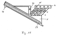
- separating device In the separating device shown in Fig. 11, four separation spaces 2 between a common upper collecting head 4 and a common lower collecting head 5 are arranged.
- a screw 33 In the lower collection head 5, a screw 33 is provided, which occurs in place of the pump 15 of FIG.
- the incoming heavy fraction stream in the collection head 5 is divided as follows: the solid particles of the heavy fraction are discharged by means of the screw 33 at 34 above the height of the outlets 35 in the collection head 4, whereas the release agent of the stream preferably with a volume-controlled pump for Maintaining constant flow velocities in the separation chamber 2 via the opening 32 is discharged.
Landscapes
- Engineering & Computer Science (AREA)
- Environmental & Geological Engineering (AREA)
- Mechanical Engineering (AREA)
- Separation Of Solids By Using Liquids Or Pneumatic Power (AREA)
- Combined Means For Separation Of Solids (AREA)
- Centrifugal Separators (AREA)
- Processing Of Solid Wastes (AREA)
- Separation, Recovery Or Treatment Of Waste Materials Containing Plastics (AREA)
Priority Applications (8)
| Application Number | Priority Date | Filing Date | Title |
|---|---|---|---|
| DE200420021641 DE202004021641U1 (de) | 2004-07-20 | 2004-07-20 | Vorrichtung zum Schwimm-Sink Trennen von Feststoffteilchen unterschiedlicher Dichte |
| DE200450008030 DE502004008030D1 (de) | 2004-07-20 | 2004-07-20 | Vorrichtung und Verfahren zum Schwimm-Sink Trennen von Feststoffteilchen unterschiedlicher Dichte |
| EP20040017065 EP1618960B1 (fr) | 2004-07-20 | 2004-07-20 | Dispositif et procédé de séparation des particules solides plongeantes et flottantes à densités différentes |
| AT04017065T ATE407738T1 (de) | 2004-07-20 | 2004-07-20 | Vorrichtung und verfahren zum schwimm-sink trennen von feststoffteilchen unterschiedlicher dichte |
| PL04017065T PL1618960T3 (pl) | 2004-07-20 | 2004-07-20 | Urządzenie i sposób rozdzielania pływających od opadających cząstek stałych o różnej gęstości |
| ES08015886T ES2395572T3 (es) | 2004-07-20 | 2004-07-20 | Dispositivo y procedimiento para la separación por flotación e inmersión de partículas sólidas de diferente densidad |
| PL08015886T PL2033713T3 (pl) | 2004-07-20 | 2004-07-20 | Urządzenie i sposób do rozdzielania pływających od opadających cząstek stałych o różnej gęstości |
| EP20080015886 EP2033713B1 (fr) | 2004-07-20 | 2004-07-20 | Dispositif et procédé de séparation des particules solides plongeantes et flottantes à densités différentes |
Applications Claiming Priority (1)
| Application Number | Priority Date | Filing Date | Title |
|---|---|---|---|
| EP20040017065 EP1618960B1 (fr) | 2004-07-20 | 2004-07-20 | Dispositif et procédé de séparation des particules solides plongeantes et flottantes à densités différentes |
Related Child Applications (1)
| Application Number | Title | Priority Date | Filing Date |
|---|---|---|---|
| EP20080015886 Division EP2033713B1 (fr) | 2004-07-20 | 2004-07-20 | Dispositif et procédé de séparation des particules solides plongeantes et flottantes à densités différentes |
Publications (2)
| Publication Number | Publication Date |
|---|---|
| EP1618960A1 true EP1618960A1 (fr) | 2006-01-25 |
| EP1618960B1 EP1618960B1 (fr) | 2008-09-10 |
Family
ID=34925820
Family Applications (2)
| Application Number | Title | Priority Date | Filing Date |
|---|---|---|---|
| EP20080015886 Expired - Lifetime EP2033713B1 (fr) | 2004-07-20 | 2004-07-20 | Dispositif et procédé de séparation des particules solides plongeantes et flottantes à densités différentes |
| EP20040017065 Expired - Lifetime EP1618960B1 (fr) | 2004-07-20 | 2004-07-20 | Dispositif et procédé de séparation des particules solides plongeantes et flottantes à densités différentes |
Family Applications Before (1)
| Application Number | Title | Priority Date | Filing Date |
|---|---|---|---|
| EP20080015886 Expired - Lifetime EP2033713B1 (fr) | 2004-07-20 | 2004-07-20 | Dispositif et procédé de séparation des particules solides plongeantes et flottantes à densités différentes |
Country Status (5)
| Country | Link |
|---|---|
| EP (2) | EP2033713B1 (fr) |
| AT (1) | ATE407738T1 (fr) |
| DE (2) | DE202004021641U1 (fr) |
| ES (1) | ES2395572T3 (fr) |
| PL (2) | PL2033713T3 (fr) |
Cited By (6)
| Publication number | Priority date | Publication date | Assignee | Title |
|---|---|---|---|---|
| EP2103354A3 (fr) * | 2008-03-21 | 2010-07-28 | Fuji Xerox Co., Ltd. | Procédé de classification et appareil de classification |
| CN102256761A (zh) * | 2008-11-07 | 2011-11-23 | Apk铝和塑料股份公司 | 由混合的特别是粉碎的塑料废物中分离各有价材料的方法 |
| CZ307054B6 (cs) * | 2015-12-22 | 2017-12-20 | Ústav Chemických Procesů Av Čr, V. V. I. | Způsob rozdružování obalového kompozitního materiálu |
| CN113203665A (zh) * | 2020-01-21 | 2021-08-03 | 大唐环境产业集团股份有限公司 | 一种入炉煤颗粒度及粒径分布检测的方法 |
| CN113455665A (zh) * | 2021-07-01 | 2021-10-01 | 塔里木大学 | 一种核桃壳仁滚筒双向分离装置 |
| CN114193664A (zh) * | 2021-12-03 | 2022-03-18 | 南京大学 | 一种沉积物中微塑料浮选分级分离装置及其方法 |
Families Citing this family (3)
| Publication number | Priority date | Publication date | Assignee | Title |
|---|---|---|---|---|
| CZ307720B6 (cs) | 2017-08-02 | 2019-03-20 | Plastigram Industries A.S. | Způsob zpracování odpadu vznikajícího po recyklaci papíru z použitých nápojových kartónů |
| CN111420601A (zh) * | 2020-03-30 | 2020-07-17 | 宋婷 | 一种清洁环保生物质取暖颗粒制备设备 |
| DE102022107082A1 (de) | 2022-03-25 | 2023-09-28 | Johannes Wissing | Verfahren zur Behandlung von Abfallstoffen, und Anlage zur Behandlung |
Citations (6)
| Publication number | Priority date | Publication date | Assignee | Title |
|---|---|---|---|---|
| CH628007A5 (fr) * | 1978-12-22 | 1982-02-15 | Francois Pfulg | Appareil de fermentation anaerobie de matieres organiques en dispersion aqueuse pour la production de methane. |
| DD235376A3 (de) * | 1983-12-22 | 1986-05-07 | Alfred Mey | Trennsaeule zum kontinuierlichen trennen von plastabfallgemischen |
| FR2573340A1 (fr) * | 1984-11-19 | 1986-05-23 | Famechon Rene | Procede de separation et de traitement de dechets de plastiques en vue de leur reutilisation et dispositif pour sa mise en oeuvre |
| DE3912385A1 (de) * | 1988-04-14 | 1989-10-26 | Gni I Pi Obogasceniju Rud Cvet | Schwerkraftkonzentrator |
| DE4315480A1 (de) * | 1993-05-10 | 1994-11-17 | Refakt Anlagenbau Gmbh | Vorrichtung zum Trennen von Kunststoff-Abfällen |
| DE19632494C1 (de) * | 1996-08-12 | 1998-01-29 | F & P Sortiertechnik Gmbh | Vorrichtung zum Sortieren von Gemischen aus Kunststoffschnitzeln |
Family Cites Families (6)
| Publication number | Priority date | Publication date | Assignee | Title |
|---|---|---|---|---|
| US2451528A (en) * | 1943-06-28 | 1948-10-19 | James A Armstrong | Method for separating worm-damaged nuts from sound nuts by immersion in a gravity liquid |
| US5431347A (en) * | 1991-12-02 | 1995-07-11 | Hitachi, Ltd. | System and method for disposing waste |
| DE4209277A1 (de) * | 1992-02-11 | 1993-08-12 | Kloeckner Humboldt Deutz Ag | Vorrichtung zur sortierung von feststoffgemischen |
| DE4309326A1 (de) * | 1993-03-18 | 1994-09-22 | Ingeborg Dr Pagenkopf | Trennvorrichtung zur kontinuierlichen Fraktionierung von Feststoffgemischen |
| EP1161302B1 (fr) | 1999-03-04 | 2004-02-18 | Behnsen, Silke | Installation et dispositif pour diviser des melanges de matieres de differentes densites |
| DE19930161A1 (de) | 1999-06-30 | 2001-01-04 | Stf Maschinen Und Anlagenbau G | Verfahren zur Trennung von Kunststoffgemischen unterschiedlicher Dichte in Fraktionen, die charakterisiert sind durch obere und untere Dichtedifferenz der einzelnen Partikel zum verwendeten flüssigen Trenn- und Transportmedium und der wirkenden Auf- bzw. Abtriebskraft auf die Partikel im flüssigen Trenn- und Transportmedium |
-
2004
- 2004-07-20 PL PL08015886T patent/PL2033713T3/pl unknown
- 2004-07-20 ES ES08015886T patent/ES2395572T3/es not_active Expired - Lifetime
- 2004-07-20 EP EP20080015886 patent/EP2033713B1/fr not_active Expired - Lifetime
- 2004-07-20 DE DE200420021641 patent/DE202004021641U1/de not_active Expired - Lifetime
- 2004-07-20 EP EP20040017065 patent/EP1618960B1/fr not_active Expired - Lifetime
- 2004-07-20 AT AT04017065T patent/ATE407738T1/de not_active IP Right Cessation
- 2004-07-20 DE DE200450008030 patent/DE502004008030D1/de not_active Expired - Lifetime
- 2004-07-20 PL PL04017065T patent/PL1618960T3/pl unknown
Patent Citations (6)
| Publication number | Priority date | Publication date | Assignee | Title |
|---|---|---|---|---|
| CH628007A5 (fr) * | 1978-12-22 | 1982-02-15 | Francois Pfulg | Appareil de fermentation anaerobie de matieres organiques en dispersion aqueuse pour la production de methane. |
| DD235376A3 (de) * | 1983-12-22 | 1986-05-07 | Alfred Mey | Trennsaeule zum kontinuierlichen trennen von plastabfallgemischen |
| FR2573340A1 (fr) * | 1984-11-19 | 1986-05-23 | Famechon Rene | Procede de separation et de traitement de dechets de plastiques en vue de leur reutilisation et dispositif pour sa mise en oeuvre |
| DE3912385A1 (de) * | 1988-04-14 | 1989-10-26 | Gni I Pi Obogasceniju Rud Cvet | Schwerkraftkonzentrator |
| DE4315480A1 (de) * | 1993-05-10 | 1994-11-17 | Refakt Anlagenbau Gmbh | Vorrichtung zum Trennen von Kunststoff-Abfällen |
| DE19632494C1 (de) * | 1996-08-12 | 1998-01-29 | F & P Sortiertechnik Gmbh | Vorrichtung zum Sortieren von Gemischen aus Kunststoffschnitzeln |
Non-Patent Citations (1)
| Title |
|---|
| DATABASE WPI Section Ch Week 197507, Derwent World Patents Index; Class J01, AN 1975-12284W, XP002310342 * |
Cited By (8)
| Publication number | Priority date | Publication date | Assignee | Title |
|---|---|---|---|---|
| EP2103354A3 (fr) * | 2008-03-21 | 2010-07-28 | Fuji Xerox Co., Ltd. | Procédé de classification et appareil de classification |
| CN102256761A (zh) * | 2008-11-07 | 2011-11-23 | Apk铝和塑料股份公司 | 由混合的特别是粉碎的塑料废物中分离各有价材料的方法 |
| CN102256761B (zh) * | 2008-11-07 | 2015-09-30 | Apk铝和塑料股份公司 | 由混合的特别是粉碎的塑料废物中分离各有价材料的方法 |
| CZ307054B6 (cs) * | 2015-12-22 | 2017-12-20 | Ústav Chemických Procesů Av Čr, V. V. I. | Způsob rozdružování obalového kompozitního materiálu |
| CN113203665A (zh) * | 2020-01-21 | 2021-08-03 | 大唐环境产业集团股份有限公司 | 一种入炉煤颗粒度及粒径分布检测的方法 |
| CN113203665B (zh) * | 2020-01-21 | 2023-01-20 | 大唐环境产业集团股份有限公司 | 一种入炉煤颗粒度及粒径分布检测的方法 |
| CN113455665A (zh) * | 2021-07-01 | 2021-10-01 | 塔里木大学 | 一种核桃壳仁滚筒双向分离装置 |
| CN114193664A (zh) * | 2021-12-03 | 2022-03-18 | 南京大学 | 一种沉积物中微塑料浮选分级分离装置及其方法 |
Also Published As
| Publication number | Publication date |
|---|---|
| ES2395572T3 (es) | 2013-02-13 |
| DE502004008030D1 (de) | 2008-10-23 |
| EP2033713A3 (fr) | 2009-08-26 |
| PL1618960T3 (pl) | 2009-04-30 |
| EP1618960B1 (fr) | 2008-09-10 |
| EP2033713A2 (fr) | 2009-03-11 |
| DE202004021641U1 (de) | 2009-09-10 |
| EP2033713B1 (fr) | 2012-09-12 |
| ATE407738T1 (de) | 2008-09-15 |
| PL2033713T3 (pl) | 2013-04-30 |
Similar Documents
| Publication | Publication Date | Title |
|---|---|---|
| EP2500102B1 (fr) | Dispositif de flottation avec un élément de distribution d'un fluide pouvant générer un courant du fluide vers le collecteur en mousse | |
| EP2680975A1 (fr) | Dispositif de flottation, procédé destiné à faire fonctionner ledit dispositif de flottation ainsi que leur utilisation | |
| EP1618960B1 (fr) | Dispositif et procédé de séparation des particules solides plongeantes et flottantes à densités différentes | |
| EP1943005A1 (fr) | Procédé et dispositif permettant d épaissir la boue charriee par les eaux usées | |
| DE19645142A1 (de) | Verfahren und Vorrichtung zum Recyceln von Sanden | |
| DE4422361C2 (de) | Verfahren zur sedimentativen Trennung von Partikeln und/oder Flüssigkeitströpfchen verschieden kompressibler Stoffe, deren Dichten bei Normalbedingungen ähnlich sind und die in Suspensionen, Emulsionen, Aerosolen oder Schwebstäuben gelöst, in Schwebe gehalten oder verstäubt sind | |
| DE2133802A1 (de) | Verfahren zur aufbereitung von mineralischen korngemengen nach der dichte und vorrichtung zur durchfuehrung des verfahrens | |
| DE19844006A1 (de) | Sandwäsche | |
| EP2170606B1 (fr) | Filtration pour machines d'impression | |
| DE2747322A1 (de) | Verfahren und vorrichtung zum abtrennen von feststoffen von einer fluessigkeit | |
| EP2818250A1 (fr) | Procédé de préparation de cendres d'incinération de déchets | |
| DE202004011327U1 (de) | Vorrichtung zum Schwimm-Sink Trennen von Feststoffteilchen unterschiedlicher Dichte | |
| DE2359656C3 (de) | Vorrichtung zum Klären von feste Stoffe enthaltendem Abwasser o.dgl. Flüssigkeiten | |
| DE19902148C2 (de) | Tangentiale Feststoffabtrenn-Vorrichtung | |
| EP0998341A1 (fr) | Procede et dispositif pour separer des matieres, et dispositif de guidage utilise a cet effet | |
| DE19617501C2 (de) | Verfahren zur Trennung der Bestandteile von kommunalen Reststoffen | |
| EP0980712A1 (fr) | Procédé et dispositif pour séparer un matériau absorbant et flottant de mélanges de substances par le procédé des plongeants et flottants | |
| DE19750983B4 (de) | Anlage und Verfahren zur Trennung von Stoffgemischen unterschiedlicher Dichte | |
| DE19981222C1 (de) | Anlage und Verfahren zur Trennung von Stoffgemischen unterschiedlicher Dichte | |
| AT504827A1 (de) | Vorrichtung zum trennen von flüssigkeit und in der flüssigkeit fein verteilten, nicht-löslichen partikeln | |
| DE19964175A1 (de) | Anlage und Verfahren zur Trennung von Stoffgemischen unterschiedlicher Dichte | |
| DE4417693C1 (de) | Verfahren und Vorrichtung zum Sortieren von Gemischen aus Kunststoffschnitzeln unterschiedlicher Dichte | |
| WO2017005801A1 (fr) | Séparateur tangentiel | |
| DE19653328A1 (de) | Vorrichtung zum Trennen einer Materialmischung, insbesondere einer Bauschuttmischung | |
| WO2024165092A1 (fr) | Agencement pour le contrôle autonome de niveaux de liquide dans une méthode de recyclage de plastique |
Legal Events
| Date | Code | Title | Description |
|---|---|---|---|
| PUAI | Public reference made under article 153(3) epc to a published international application that has entered the european phase |
Free format text: ORIGINAL CODE: 0009012 |
|
| 17P | Request for examination filed |
Effective date: 20040816 |
|
| AK | Designated contracting states |
Kind code of ref document: A1 Designated state(s): AT BE BG CH CY CZ DE DK EE ES FI FR GB GR HU IE IT LI LU MC NL PL PT RO SE SI SK TR |
|
| AX | Request for extension of the european patent |
Extension state: AL HR LT LV MK |
|
| AKX | Designation fees paid |
Designated state(s): AT BE BG CH CY CZ DE DK EE ES FI FR GB GR HU IE IT LI LU MC NL PL PT RO SE SI SK TR |
|
| 17Q | First examination report despatched |
Effective date: 20061011 |
|
| GRAP | Despatch of communication of intention to grant a patent |
Free format text: ORIGINAL CODE: EPIDOSNIGR1 |
|
| GRAS | Grant fee paid |
Free format text: ORIGINAL CODE: EPIDOSNIGR3 |
|
| GRAA | (expected) grant |
Free format text: ORIGINAL CODE: 0009210 |
|
| AK | Designated contracting states |
Kind code of ref document: B1 Designated state(s): AT BE BG CH CY CZ DE DK EE ES FI FR GB GR HU IE IT LI LU MC NL PL PT RO SE SI SK TR |
|
| REG | Reference to a national code |
Ref country code: GB Ref legal event code: FG4D Free format text: NOT ENGLISH |
|
| REG | Reference to a national code |
Ref country code: CH Ref legal event code: EP |
|
| RAP2 | Party data changed (patent owner data changed or rights of a patent transferred) |
Owner name: APK ALUMINIUM UND KUNSTSTOFFE AG |
|
| RIN2 | Information on inventor provided after grant (corrected) |
Inventor name: LINDNER DR., WOLFGANG L. |
|
| REG | Reference to a national code |
Ref country code: IE Ref legal event code: FG4D Free format text: LANGUAGE OF EP DOCUMENT: GERMAN |
|
| REF | Corresponds to: |
Ref document number: 502004008030 Country of ref document: DE Date of ref document: 20081023 Kind code of ref document: P |
|
| NLT2 | Nl: modifications (of names), taken from the european patent patent bulletin |
Owner name: APK ALUMINIUM UND KUNSTSTOFFE AG Effective date: 20080924 |
|
| PG25 | Lapsed in a contracting state [announced via postgrant information from national office to epo] |
Ref country code: SI Free format text: LAPSE BECAUSE OF FAILURE TO SUBMIT A TRANSLATION OF THE DESCRIPTION OR TO PAY THE FEE WITHIN THE PRESCRIBED TIME-LIMIT Effective date: 20080910 Ref country code: FI Free format text: LAPSE BECAUSE OF FAILURE TO SUBMIT A TRANSLATION OF THE DESCRIPTION OR TO PAY THE FEE WITHIN THE PRESCRIBED TIME-LIMIT Effective date: 20080910 |
|
| REG | Reference to a national code |
Ref country code: IE Ref legal event code: FD4D |
|
| PG25 | Lapsed in a contracting state [announced via postgrant information from national office to epo] |
Ref country code: IE Free format text: LAPSE BECAUSE OF FAILURE TO SUBMIT A TRANSLATION OF THE DESCRIPTION OR TO PAY THE FEE WITHIN THE PRESCRIBED TIME-LIMIT Effective date: 20080910 Ref country code: BG Free format text: LAPSE BECAUSE OF FAILURE TO SUBMIT A TRANSLATION OF THE DESCRIPTION OR TO PAY THE FEE WITHIN THE PRESCRIBED TIME-LIMIT Effective date: 20081210 Ref country code: ES Free format text: LAPSE BECAUSE OF FAILURE TO SUBMIT A TRANSLATION OF THE DESCRIPTION OR TO PAY THE FEE WITHIN THE PRESCRIBED TIME-LIMIT Effective date: 20081221 |
|
| REG | Reference to a national code |
Ref country code: PL Ref legal event code: T3 |
|
| PG25 | Lapsed in a contracting state [announced via postgrant information from national office to epo] |
Ref country code: RO Free format text: LAPSE BECAUSE OF FAILURE TO SUBMIT A TRANSLATION OF THE DESCRIPTION OR TO PAY THE FEE WITHIN THE PRESCRIBED TIME-LIMIT Effective date: 20080910 Ref country code: SK Free format text: LAPSE BECAUSE OF FAILURE TO SUBMIT A TRANSLATION OF THE DESCRIPTION OR TO PAY THE FEE WITHIN THE PRESCRIBED TIME-LIMIT Effective date: 20080910 Ref country code: PT Free format text: LAPSE BECAUSE OF FAILURE TO SUBMIT A TRANSLATION OF THE DESCRIPTION OR TO PAY THE FEE WITHIN THE PRESCRIBED TIME-LIMIT Effective date: 20090210 |
|
| PLBE | No opposition filed within time limit |
Free format text: ORIGINAL CODE: 0009261 |
|
| STAA | Information on the status of an ep patent application or granted ep patent |
Free format text: STATUS: NO OPPOSITION FILED WITHIN TIME LIMIT |
|
| PG25 | Lapsed in a contracting state [announced via postgrant information from national office to epo] |
Ref country code: DK Free format text: LAPSE BECAUSE OF FAILURE TO SUBMIT A TRANSLATION OF THE DESCRIPTION OR TO PAY THE FEE WITHIN THE PRESCRIBED TIME-LIMIT Effective date: 20080910 Ref country code: EE Free format text: LAPSE BECAUSE OF FAILURE TO SUBMIT A TRANSLATION OF THE DESCRIPTION OR TO PAY THE FEE WITHIN THE PRESCRIBED TIME-LIMIT Effective date: 20080910 |
|
| 26N | No opposition filed |
Effective date: 20090611 |
|
| PG25 | Lapsed in a contracting state [announced via postgrant information from national office to epo] |
Ref country code: IT Free format text: LAPSE BECAUSE OF FAILURE TO SUBMIT A TRANSLATION OF THE DESCRIPTION OR TO PAY THE FEE WITHIN THE PRESCRIBED TIME-LIMIT Effective date: 20080910 |
|
| PG25 | Lapsed in a contracting state [announced via postgrant information from national office to epo] |
Ref country code: SE Free format text: LAPSE BECAUSE OF FAILURE TO SUBMIT A TRANSLATION OF THE DESCRIPTION OR TO PAY THE FEE WITHIN THE PRESCRIBED TIME-LIMIT Effective date: 20081210 |
|
| PG25 | Lapsed in a contracting state [announced via postgrant information from national office to epo] |
Ref country code: MC Free format text: LAPSE BECAUSE OF NON-PAYMENT OF DUE FEES Effective date: 20090731 |
|
| REG | Reference to a national code |
Ref country code: CH Ref legal event code: PL |
|
| PG25 | Lapsed in a contracting state [announced via postgrant information from national office to epo] |
Ref country code: CH Free format text: LAPSE BECAUSE OF NON-PAYMENT OF DUE FEES Effective date: 20090731 Ref country code: LI Free format text: LAPSE BECAUSE OF NON-PAYMENT OF DUE FEES Effective date: 20090731 |
|
| PG25 | Lapsed in a contracting state [announced via postgrant information from national office to epo] |
Ref country code: GR Free format text: LAPSE BECAUSE OF FAILURE TO SUBMIT A TRANSLATION OF THE DESCRIPTION OR TO PAY THE FEE WITHIN THE PRESCRIBED TIME-LIMIT Effective date: 20081211 |
|
| PGFP | Annual fee paid to national office [announced via postgrant information from national office to epo] |
Ref country code: NL Payment date: 20100726 Year of fee payment: 7 |
|
| PG25 | Lapsed in a contracting state [announced via postgrant information from national office to epo] |
Ref country code: AT Free format text: LAPSE BECAUSE OF NON-PAYMENT OF DUE FEES Effective date: 20090720 |
|
| PGFP | Annual fee paid to national office [announced via postgrant information from national office to epo] |
Ref country code: CZ Payment date: 20100712 Year of fee payment: 7 |
|
| PGFP | Annual fee paid to national office [announced via postgrant information from national office to epo] |
Ref country code: PL Payment date: 20100707 Year of fee payment: 7 |
|
| PGFP | Annual fee paid to national office [announced via postgrant information from national office to epo] |
Ref country code: BE Payment date: 20100726 Year of fee payment: 7 |
|
| PG25 | Lapsed in a contracting state [announced via postgrant information from national office to epo] |
Ref country code: LU Free format text: LAPSE BECAUSE OF NON-PAYMENT OF DUE FEES Effective date: 20090720 |
|
| PG25 | Lapsed in a contracting state [announced via postgrant information from national office to epo] |
Ref country code: HU Free format text: LAPSE BECAUSE OF FAILURE TO SUBMIT A TRANSLATION OF THE DESCRIPTION OR TO PAY THE FEE WITHIN THE PRESCRIBED TIME-LIMIT Effective date: 20090311 |
|
| PG25 | Lapsed in a contracting state [announced via postgrant information from national office to epo] |
Ref country code: TR Free format text: LAPSE BECAUSE OF FAILURE TO SUBMIT A TRANSLATION OF THE DESCRIPTION OR TO PAY THE FEE WITHIN THE PRESCRIBED TIME-LIMIT Effective date: 20080910 |
|
| PG25 | Lapsed in a contracting state [announced via postgrant information from national office to epo] |
Ref country code: CY Free format text: LAPSE BECAUSE OF FAILURE TO SUBMIT A TRANSLATION OF THE DESCRIPTION OR TO PAY THE FEE WITHIN THE PRESCRIBED TIME-LIMIT Effective date: 20080910 |
|
| BERE | Be: lapsed |
Owner name: APK ALUMINIUM UND KUNSTSTOFFE AG Effective date: 20110731 |
|
| REG | Reference to a national code |
Ref country code: NL Ref legal event code: V1 Effective date: 20120201 |
|
| PG25 | Lapsed in a contracting state [announced via postgrant information from national office to epo] |
Ref country code: BE Free format text: LAPSE BECAUSE OF NON-PAYMENT OF DUE FEES Effective date: 20110731 Ref country code: CZ Free format text: LAPSE BECAUSE OF NON-PAYMENT OF DUE FEES Effective date: 20110720 |
|
| PG25 | Lapsed in a contracting state [announced via postgrant information from national office to epo] |
Ref country code: NL Free format text: LAPSE BECAUSE OF NON-PAYMENT OF DUE FEES Effective date: 20120201 |
|
| PG25 | Lapsed in a contracting state [announced via postgrant information from national office to epo] |
Ref country code: PL Free format text: LAPSE BECAUSE OF NON-PAYMENT OF DUE FEES Effective date: 20110720 |
|
| REG | Reference to a national code |
Ref country code: PL Ref legal event code: LAPE |
|
| REG | Reference to a national code |
Ref country code: FR Ref legal event code: PLFP Year of fee payment: 13 |
|
| REG | Reference to a national code |
Ref country code: FR Ref legal event code: PLFP Year of fee payment: 14 |
|
| REG | Reference to a national code |
Ref country code: DE Ref legal event code: R082 Ref document number: 502004008030 Country of ref document: DE Representative=s name: GROSSE, SCHUMACHER, KNAUER, VON HIRSCHHAUSEN, DE Ref country code: DE Ref legal event code: R082 Ref document number: 502004008030 Country of ref document: DE Representative=s name: BOEHMERT & BOEHMERT ANWALTSPARTNERSCHAFT MBB -, DE Ref country code: DE Ref legal event code: R082 Ref document number: 502004008030 Country of ref document: DE Ref country code: DE Ref legal event code: R081 Ref document number: 502004008030 Country of ref document: DE Owner name: APK AG, DE Free format text: FORMER OWNER: APK ALUMINIUM UND KUNSTSTOFFE AG, 06258 SCHKOPAU, DE |
|
| REG | Reference to a national code |
Ref country code: FR Ref legal event code: PLFP Year of fee payment: 15 |
|
| REG | Reference to a national code |
Ref country code: DE Ref legal event code: R082 Ref document number: 502004008030 Country of ref document: DE Representative=s name: BOEHMERT & BOEHMERT ANWALTSPARTNERSCHAFT MBB -, DE Ref country code: DE Ref legal event code: R082 Ref document number: 502004008030 Country of ref document: DE |
|
| REG | Reference to a national code |
Ref country code: DE Ref legal event code: R082 Ref document number: 502004008030 Country of ref document: DE Representative=s name: BOEHMERT & BOEHMERT ANWALTSPARTNERSCHAFT MBB -, DE |
|
| P01 | Opt-out of the competence of the unified patent court (upc) registered |
Effective date: 20230418 |
|
| PGFP | Annual fee paid to national office [announced via postgrant information from national office to epo] |
Ref country code: GB Payment date: 20230725 Year of fee payment: 20 |
|
| PGFP | Annual fee paid to national office [announced via postgrant information from national office to epo] |
Ref country code: FR Payment date: 20230725 Year of fee payment: 20 Ref country code: DE Payment date: 20230726 Year of fee payment: 20 |
|
| REG | Reference to a national code |
Ref country code: DE Ref legal event code: R071 Ref document number: 502004008030 Country of ref document: DE |
|
| REG | Reference to a national code |
Ref country code: GB Ref legal event code: PE20 Expiry date: 20240719 |
|
| PG25 | Lapsed in a contracting state [announced via postgrant information from national office to epo] |
Ref country code: GB Free format text: LAPSE BECAUSE OF EXPIRATION OF PROTECTION Effective date: 20240719 |
|
| PG25 | Lapsed in a contracting state [announced via postgrant information from national office to epo] |
Ref country code: GB Free format text: LAPSE BECAUSE OF EXPIRATION OF PROTECTION Effective date: 20240719 |