EP1618982A1 - Circuit d'allumage pour un appareil de soudage de goujons - Google Patents
Circuit d'allumage pour un appareil de soudage de goujons Download PDFInfo
- Publication number
- EP1618982A1 EP1618982A1 EP05105288A EP05105288A EP1618982A1 EP 1618982 A1 EP1618982 A1 EP 1618982A1 EP 05105288 A EP05105288 A EP 05105288A EP 05105288 A EP05105288 A EP 05105288A EP 1618982 A1 EP1618982 A1 EP 1618982A1
- Authority
- EP
- European Patent Office
- Prior art keywords
- ignition
- voltage
- ignition circuit
- capacitor
- thyristor
- Prior art date
- Legal status (The legal status is an assumption and is not a legal conclusion. Google has not performed a legal analysis and makes no representation as to the accuracy of the status listed.)
- Withdrawn
Links
- 238000003466 welding Methods 0.000 title claims abstract description 28
- 239000003990 capacitor Substances 0.000 claims abstract description 26
- 238000010791 quenching Methods 0.000 claims description 4
- 230000000171 quenching effect Effects 0.000 claims description 4
- 230000010354 integration Effects 0.000 description 4
- 238000000034 method Methods 0.000 description 2
- HCHKCACWOHOZIP-UHFFFAOYSA-N Zinc Chemical compound [Zn] HCHKCACWOHOZIP-UHFFFAOYSA-N 0.000 description 1
- XAGFODPZIPBFFR-UHFFFAOYSA-N aluminium Chemical compound [Al] XAGFODPZIPBFFR-UHFFFAOYSA-N 0.000 description 1
- 229910052782 aluminium Inorganic materials 0.000 description 1
- 230000000903 blocking effect Effects 0.000 description 1
- 239000003638 chemical reducing agent Substances 0.000 description 1
- 239000011248 coating agent Substances 0.000 description 1
- 238000000576 coating method Methods 0.000 description 1
- 230000000295 complement effect Effects 0.000 description 1
- 238000005260 corrosion Methods 0.000 description 1
- 230000007797 corrosion Effects 0.000 description 1
- 238000007599 discharging Methods 0.000 description 1
- 239000006185 dispersion Substances 0.000 description 1
- 238000005516 engineering process Methods 0.000 description 1
- 238000010304 firing Methods 0.000 description 1
- 239000000463 material Substances 0.000 description 1
- 239000011435 rock Substances 0.000 description 1
- 239000011701 zinc Substances 0.000 description 1
- 229910052725 zinc Inorganic materials 0.000 description 1
Images

Classifications
-
- B—PERFORMING OPERATIONS; TRANSPORTING
- B23—MACHINE TOOLS; METAL-WORKING NOT OTHERWISE PROVIDED FOR
- B23K—SOLDERING OR UNSOLDERING; WELDING; CLADDING OR PLATING BY SOLDERING OR WELDING; CUTTING BY APPLYING HEAT LOCALLY, e.g. FLAME CUTTING; WORKING BY LASER BEAM
- B23K9/00—Arc welding or cutting
- B23K9/20—Stud welding
- B23K9/205—Means for determining, controlling or regulating the arc interval
Definitions
- the invention relates to an ignition circuit for a stud welder, in which the sparking energy of a capacitor bank is taken to the top ignition, the capacitors are discharged by ignition of thyristors.
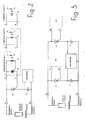
- FIG. 3 shows an alternative standard circuit which is in use to provide a plurality of stud sizes via capacitance switching to be able to weld.
- the ignition circuits ZS used in this case correspond to the variants indicated in FIG.
- Capacity switching is used when a variable capacity is required, depending on the size of the bolt.
- the welding and discharging time will be longer. This can lead to certain materials, eg. As aluminum, no longer be welded securely.
- the cause of this discharge behavior is the decrease of the ignition voltage for the thyristors from the common welding voltage connection. Due to the physical parameter dispersion of the components (thyristors TH1 and TH2) and the ignition or trigger circuit, a thyristor will always fire first. Thus, the second thyristor lacks the necessary voltage difference to ignite as well. Only then, when the first ignited thyristor has discharged the capacitor C to a certain voltage, the ignition voltage is available for the second thyristor TH2.
- the ignition or trigger circuit according to the invention shown in Figure 1 eliminates the one hand, the disadvantages of the known circuit technology and on the other hand additionally allows a controlled, mutual discharge of the capacitors, so as to influence the welding time specifically.
- a double-pulse welding can be performed.
- the goal is to burn away with the first welding pulse, for example, a surface coating, such as zinc, bonder layer or corrosion protection, or melt, and then selectively bring the actual welding energy in the weld.
Landscapes
- Engineering & Computer Science (AREA)
- Physics & Mathematics (AREA)
- Plasma & Fusion (AREA)
- Mechanical Engineering (AREA)
- Generation Of Surge Voltage And Current (AREA)
- Arc Welding Control (AREA)
Applications Claiming Priority (1)
| Application Number | Priority Date | Filing Date | Title |
|---|---|---|---|
| DE200410034752 DE102004034752A1 (de) | 2004-07-17 | 2004-07-17 | Zündschaltung für ein Bolzenschweißgerät |
Publications (1)
| Publication Number | Publication Date |
|---|---|
| EP1618982A1 true EP1618982A1 (fr) | 2006-01-25 |
Family
ID=35335719
Family Applications (1)
| Application Number | Title | Priority Date | Filing Date |
|---|---|---|---|
| EP05105288A Withdrawn EP1618982A1 (fr) | 2004-07-17 | 2005-06-16 | Circuit d'allumage pour un appareil de soudage de goujons |
Country Status (2)
| Country | Link |
|---|---|
| EP (1) | EP1618982A1 (fr) |
| DE (1) | DE102004034752A1 (fr) |
Citations (5)
| Publication number | Priority date | Publication date | Assignee | Title |
|---|---|---|---|---|
| US3805143A (en) * | 1971-02-19 | 1974-04-16 | Hihi Ag | Capacitor-discharge stud welding apparatus |
| JPS589773A (ja) * | 1981-07-08 | 1983-01-20 | Fujio Nakamae | コンデンサ放電形スタッド溶接機の溶接電流制御方法 |
| DE3614271A1 (de) * | 1986-04-26 | 1987-10-29 | Kriegeskorte & Co Gmbh | Tragbares bolzenschweissgeraet |
| DE9406367U1 (de) * | 1994-04-16 | 1994-08-04 | Obo Bettermann Ohg, 58710 Menden | Schaltungsanordnung zum Anschweißen von Schweißbolzen o.dgl. Schweißelementen an ein Werkstück im Wege des Kondensatorentladungsverfahrens |
| DE4331200C1 (de) * | 1993-09-14 | 1994-11-03 | Hbs Bolzenschweisssysteme Gmbh | Schaltungsanordnung zum Steuern eines Schweißstromes |
-
2004
- 2004-07-17 DE DE200410034752 patent/DE102004034752A1/de not_active Withdrawn
-
2005
- 2005-06-16 EP EP05105288A patent/EP1618982A1/fr not_active Withdrawn
Patent Citations (5)
| Publication number | Priority date | Publication date | Assignee | Title |
|---|---|---|---|---|
| US3805143A (en) * | 1971-02-19 | 1974-04-16 | Hihi Ag | Capacitor-discharge stud welding apparatus |
| JPS589773A (ja) * | 1981-07-08 | 1983-01-20 | Fujio Nakamae | コンデンサ放電形スタッド溶接機の溶接電流制御方法 |
| DE3614271A1 (de) * | 1986-04-26 | 1987-10-29 | Kriegeskorte & Co Gmbh | Tragbares bolzenschweissgeraet |
| DE4331200C1 (de) * | 1993-09-14 | 1994-11-03 | Hbs Bolzenschweisssysteme Gmbh | Schaltungsanordnung zum Steuern eines Schweißstromes |
| DE9406367U1 (de) * | 1994-04-16 | 1994-08-04 | Obo Bettermann Ohg, 58710 Menden | Schaltungsanordnung zum Anschweißen von Schweißbolzen o.dgl. Schweißelementen an ein Werkstück im Wege des Kondensatorentladungsverfahrens |
Non-Patent Citations (1)
| Title |
|---|
| PATENT ABSTRACTS OF JAPAN vol. 007, no. 085 (M - 206) 8 April 1983 (1983-04-08) * |
Also Published As
| Publication number | Publication date |
|---|---|
| DE102004034752A1 (de) | 2006-02-02 |
Similar Documents
| Publication | Publication Date | Title |
|---|---|---|
| DE102007041674B4 (de) | Elektrischer Schaltkreis mit integriertem Schutz vor Ausgleichsvorgängen | |
| DE102017219499A1 (de) | Elektrische Anordnung mit Teilmodulen sowie Teilmodule als solche | |
| DE2936279C3 (de) | Leistungsschaltervorrichtung | |
| WO2010079066A1 (fr) | Dispositif d'alimentation électrique d'une charge | |
| EP3403270A1 (fr) | Commutateur pour courant continu | |
| DE2362472C3 (de) | Zündanlage mit Magnetgenerator für Brennkraftmaschinen | |
| DE1539369B2 (de) | Elektrische Schaltungsanordnung für eine Entladungslampe | |
| EP3361596B1 (fr) | Batterie avec un système de gestion de batterie comprenant un dispositif interrupteur | |
| DE69008836T2 (de) | Schaltungsanordnung, geeignet zum Zünden einer Hochdruckentladungslampe. | |
| EP1618982A1 (fr) | Circuit d'allumage pour un appareil de soudage de goujons | |
| DE3234702C2 (fr) | ||
| DE10256121A1 (de) | Umschaltbarer Gleichstromwandler für ein Netz mit zwei Spannungen und ein Netz mit zwei Spannungen, das mit einem derartigen Wandler ausgestattet ist | |
| WO2020030262A1 (fr) | Système pourvu d'un commutateur de pontage | |
| DE3835869C2 (fr) | ||
| DE2246258C3 (de) | Schaltungsanordnung zur Gleichstromspeisung eines mit einer Freilaufdiode beschalteten Verbrauchers | |
| DE2030154A1 (de) | Startschaltung fur Wechselrichter | |
| DE2057722C3 (de) | Überspannungsschutz anordnung | |
| DE4100719A1 (de) | Schaltung zur stabilisierten erzeugung von hochspannungsimpulsen | |
| DE2242415C2 (de) | Schaltungsanordnung zum Schutz eines Wechselrichters | |
| EP3745572A1 (fr) | Agencement de circuit pour un système de traction | |
| DE2257754C2 (de) | Elektronische Anordnung zur Steuerung eines Gleichstroms | |
| DE2855425A1 (de) | Elektrische schaltung fuer eine hochfrequenz-lichtbogenschweissvorrichtung | |
| DE1956231C3 (de) | Schaltungsanordnung zur Herabsetzung der Spannungsbeanspruchung einer zerhackergesteuerten Schaltung | |
| DE69312158T2 (de) | Entlastungsvorrichtung für in einem mit Gleichstrom gespeisten Leistungswandler seriengeschaltete Leistungsschalterbauteile | |
| DE2443065C2 (de) | Wechselrichterschaltungsanordnung |
Legal Events
| Date | Code | Title | Description |
|---|---|---|---|
| PUAI | Public reference made under article 153(3) epc to a published international application that has entered the european phase |
Free format text: ORIGINAL CODE: 0009012 |
|
| AK | Designated contracting states |
Kind code of ref document: A1 Designated state(s): AT BE BG CH CY CZ DE DK EE ES FI FR GB GR HU IE IS IT LI LT LU MC NL PL PT RO SE SI SK TR |
|
| AX | Request for extension of the european patent |
Extension state: AL BA HR LV MK YU |
|
| AKX | Designation fees paid | ||
| STAA | Information on the status of an ep patent application or granted ep patent |
Free format text: STATUS: THE APPLICATION IS DEEMED TO BE WITHDRAWN |
|
| 18D | Application deemed to be withdrawn |
Effective date: 20060726 |
|
| REG | Reference to a national code |
Ref country code: DE Ref legal event code: 8566 |