EP1619151A2 - Margeur de feuilles pour faciliter le montage, le démontage et le remplacement des éléments et procédé pour le calibrage du contrôle de double feuille - Google Patents
Margeur de feuilles pour faciliter le montage, le démontage et le remplacement des éléments et procédé pour le calibrage du contrôle de double feuille Download PDFInfo
- Publication number
- EP1619151A2 EP1619151A2 EP05106062A EP05106062A EP1619151A2 EP 1619151 A2 EP1619151 A2 EP 1619151A2 EP 05106062 A EP05106062 A EP 05106062A EP 05106062 A EP05106062 A EP 05106062A EP 1619151 A2 EP1619151 A2 EP 1619151A2
- Authority
- EP
- European Patent Office
- Prior art keywords
- sheet
- gripper shaft
- feeder
- gripper
- camshaft
- Prior art date
- Legal status (The legal status is an assumption and is not a legal conclusion. Google has not performed a legal analysis and makes no representation as to the accuracy of the status listed.)
- Granted
Links
Images




Classifications
-
- B—PERFORMING OPERATIONS; TRANSPORTING
- B65—CONVEYING; PACKING; STORING; HANDLING THIN OR FILAMENTARY MATERIAL
- B65H—HANDLING THIN OR FILAMENTARY MATERIAL, e.g. SHEETS, WEBS, CABLES
- B65H7/00—Controlling article feeding, separating, pile-advancing, or associated apparatus, to take account of incorrect feeding, absence of articles, or presence of faulty articles
- B65H7/02—Controlling article feeding, separating, pile-advancing, or associated apparatus, to take account of incorrect feeding, absence of articles, or presence of faulty articles by feelers or detectors
- B65H7/06—Controlling article feeding, separating, pile-advancing, or associated apparatus, to take account of incorrect feeding, absence of articles, or presence of faulty articles by feelers or detectors responsive to presence of faulty articles or incorrect separation or feed
- B65H7/12—Controlling article feeding, separating, pile-advancing, or associated apparatus, to take account of incorrect feeding, absence of articles, or presence of faulty articles by feelers or detectors responsive to presence of faulty articles or incorrect separation or feed responsive to double feed or separation
-
- B—PERFORMING OPERATIONS; TRANSPORTING
- B65—CONVEYING; PACKING; STORING; HANDLING THIN OR FILAMENTARY MATERIAL
- B65H—HANDLING THIN OR FILAMENTARY MATERIAL, e.g. SHEETS, WEBS, CABLES
- B65H3/00—Separating articles from piles
- B65H3/08—Separating articles from piles using pneumatic force
- B65H3/0808—Suction grippers
- B65H3/085—Suction grippers separating from the bottom of pile
- B65H3/0858—Suction grippers separating from the bottom of pile this action resulting merely in a curvature of each article being separated
- B65H3/0875—Suction grippers separating from the bottom of pile this action resulting merely in a curvature of each article being separated the final separation being performed by mechanical grippers
-
- B—PERFORMING OPERATIONS; TRANSPORTING
- B65—CONVEYING; PACKING; STORING; HANDLING THIN OR FILAMENTARY MATERIAL
- B65H—HANDLING THIN OR FILAMENTARY MATERIAL, e.g. SHEETS, WEBS, CABLES
- B65H3/00—Separating articles from piles
- B65H3/44—Simultaneously, alternately, or selectively separating articles from two or more piles
-
- B—PERFORMING OPERATIONS; TRANSPORTING
- B65—CONVEYING; PACKING; STORING; HANDLING THIN OR FILAMENTARY MATERIAL
- B65H—HANDLING THIN OR FILAMENTARY MATERIAL, e.g. SHEETS, WEBS, CABLES
- B65H2220/00—Function indicators
- B65H2220/02—Function indicators indicating an entity which is controlled, adjusted or changed by a control process, i.e. output
-
- B—PERFORMING OPERATIONS; TRANSPORTING
- B65—CONVEYING; PACKING; STORING; HANDLING THIN OR FILAMENTARY MATERIAL
- B65H—HANDLING THIN OR FILAMENTARY MATERIAL, e.g. SHEETS, WEBS, CABLES
- B65H2402/00—Constructional details of the handling apparatus
- B65H2402/10—Modular constructions, e.g. using preformed elements or profiles
-
- B—PERFORMING OPERATIONS; TRANSPORTING
- B65—CONVEYING; PACKING; STORING; HANDLING THIN OR FILAMENTARY MATERIAL
- B65H—HANDLING THIN OR FILAMENTARY MATERIAL, e.g. SHEETS, WEBS, CABLES
- B65H2403/00—Power transmission; Driving means
- B65H2403/50—Driving mechanisms
- B65H2403/51—Cam mechanisms
- B65H2403/512—Cam mechanisms involving radial plate cam
-
- B—PERFORMING OPERATIONS; TRANSPORTING
- B65—CONVEYING; PACKING; STORING; HANDLING THIN OR FILAMENTARY MATERIAL
- B65H—HANDLING THIN OR FILAMENTARY MATERIAL, e.g. SHEETS, WEBS, CABLES
- B65H2511/00—Dimensions; Position; Numbers; Identification; Occurrences
- B65H2511/10—Size; Dimensions
- B65H2511/13—Thickness
-
- B—PERFORMING OPERATIONS; TRANSPORTING
- B65—CONVEYING; PACKING; STORING; HANDLING THIN OR FILAMENTARY MATERIAL
- B65H—HANDLING THIN OR FILAMENTARY MATERIAL, e.g. SHEETS, WEBS, CABLES
- B65H2511/00—Dimensions; Position; Numbers; Identification; Occurrences
- B65H2511/50—Occurence
- B65H2511/52—Defective operating conditions
- B65H2511/524—Multiple articles, e.g. double feed
-
- B—PERFORMING OPERATIONS; TRANSPORTING
- B65—CONVEYING; PACKING; STORING; HANDLING THIN OR FILAMENTARY MATERIAL
- B65H—HANDLING THIN OR FILAMENTARY MATERIAL, e.g. SHEETS, WEBS, CABLES
- B65H2551/00—Means for control to be used by operator; User interfaces
- B65H2551/20—Display means; Information output means
-
- B—PERFORMING OPERATIONS; TRANSPORTING
- B65—CONVEYING; PACKING; STORING; HANDLING THIN OR FILAMENTARY MATERIAL
- B65H—HANDLING THIN OR FILAMENTARY MATERIAL, e.g. SHEETS, WEBS, CABLES
- B65H2557/00—Means for control not provided for in groups B65H2551/00 - B65H2555/00
- B65H2557/60—Details of processes or procedures
- B65H2557/61—Details of processes or procedures for calibrating
-
- B—PERFORMING OPERATIONS; TRANSPORTING
- B65—CONVEYING; PACKING; STORING; HANDLING THIN OR FILAMENTARY MATERIAL
- B65H—HANDLING THIN OR FILAMENTARY MATERIAL, e.g. SHEETS, WEBS, CABLES
- B65H2601/00—Problem to be solved or advantage achieved
- B65H2601/30—Facilitating or easing
- B65H2601/32—Facilitating or easing entities relating to handling machine
- B65H2601/324—Removability or inter-changeability of machine parts, e.g. for maintenance
Definitions
- the invention relates to a feeder for feeding sheets according to the preamble of claim 1.
- devices of the type mentioned are used to feed sheets to a sheet processing apparatus.
- a plurality of such feeders are often used to collect different sheets on a collection line.
- the collected sheets are subsequently stapled or adhesively bonded, for example.
- sheet separating elements are used, which ensure that the grippers on the gripper drums extract only one sheet at a time.
- the sheet separation elements such as retention fingers, suction air grippers or fuzzers, are mechanically cam controlled. These cams for the sheet separating elements and the gripper drums are mounted in the prior art on a shaft which is mounted in the side walls of the investor.
- the grippers or gripper drums are arranged on at least one gripper shaft and the plurality of curves for controlling Bogensepar ists instituten arranged on a separate from the at least one gripper shaft camshaft.
- the separation of the gripper shaft and the cam shaft reduces the number of elements on the respective shaft.
- the individual waves are easier to handle and access to elements that lie further inward on a shaft is facilitated.
- Such elements require that all other elements located between this element and the end of the shaft be removed first before this element can be removed. Accordingly, the time required to remove the other elements is shortened by having fewer elements mounted on the shaft. The installation or removal of the entire shaft is facilitated by the reduced number of elements on the respective shaft.
- the at least one gripper shaft and the cam shaft on a common drive.
- the least one gripper shaft with a gear with the camshaft is connectable.
- the transmission may be two gears mounted on the respective shaft and engaged with each other.
- other transmissions such as a toothed belt or other mechanisms known in the art can be used.
- the transmission between gripper shaft and cam shaft also includes a coupling with which the camshaft can be disengaged from the gripper shaft.
- the gripper shaft is mounted in a gripper shaft unit, the feeder housing having at least one receiving space for the gripper shaft unit to which the gripper shaft unit together with the gripper shaft and the grippers is releasably fastened.
- the production of the entire investor is facilitated by this measure, since the feeder and the gripper shaft unit can be made in parallel and can be joined together at a later date in a simple manner. Since the camshaft is not in the gripper shaft unit, in addition, in an eventual replacement of elements on the gripper shaft, and thus an expansion of the gripper shaft unit, the adjusted position of the camshaft is not changed. This eliminates annoying readjustments on the cam shaft when the gripper shaft unit is reinstalled together with the gripper shaft.
- the camshaft is mounted in a camshaft unit, wherein the feeder housing has at least one receiving space for the cam shaft unit on which the cam shaft unit can be fastened together with the cam shaft around the curves for controlling the Bogensepar ists institute.
- the camshaft assembly can be assembled outside the feeder housing, disassembled and maintained. Likewise eliminates annoying readjustments on the gripper shaft when the camshaft unit is reinstalled together with the camshaft.
- two of the gripper shaft units are releasably fastened in an investor and releasably securable between the gripper shaft units a cam shaft unit, wherein the cam shaft unit includes the curves for controlling the Bogensepar ists institute the entire investor.
- a coupling between the two gripper shaft units is provided, which enables a transmission of the drive from the first gripper shaft unit to the second gripper shaft unit.
- the provision of two gripper shaft units essentially means the division of a longer gripper shaft into two shorter gripper shafts.
- the sheet separation elements are at least one of the following suction air grippers, suction air supply, retention fingers.
- the suction air gripper is a gripper which sucks the front end of the lower sheet of the stack due to a negative pressure on the Saugluftgreifer and brings down into the reach of the gripper of the gripper drums.
- the suction air supply is controlled so that the suction air is cut off on Saugluftgreifer when the gripper of the gripper drums has detected the bottom sheet, or is turned on when the Saugluftgreifer should take the next sheet.
- the retention finger serves to separate sheets that are above the lowermost sheet of the stack from the lowermost sheet.
- Further sheet separating elements could be, for example, blowing air nozzles which fan out the lower stack in the region of the suction air gripper so that no further sheet adheres to the lowermost sheet.
- the at least one gripper shaft has grippers for withdrawing sheets from two stacks. Basically are also grippers for the removal of more than two stacks conceivable with increasing number of stacks but also increases the length of the gripper shaft and thus reduce the benefits of segmentation of the gripper shaft.
- the feeder collects the sheets in a collecting channel, wherein the channel is arranged substantially vertically, and wherein the width of the channel is automatically adjustable.
- the width of the channel is automatically adjustable.
- the invention also relates to a collecting device with a drive unit and at least one feeder according to claim 1, wherein the collecting device additionally comprises a contact unit for manual installation. This makes it possible to feed already pre-collected stacks more sheets when the pre-collected stacks are inserted into the manual insert
- the thickness detector provides only an electronic signal, which it can use as a standard of comparison between the normal arc and the sample sheet.
- Such a calibration is independent of the material of the sample sheet, the thickness or environmental conditions such as humidity, temperature, etc., since the calibration by the sample sheet advantageously takes place immediately before normal operation, so that these environmental conditions have hardly changed for normal operation.
- the step of providing comprises providing a thickness detector in the transport path of a cover feeder of a multi-pincer adhesive binder.
- the step comprises the provision of a detector in the transport path of each feeder of a collection unit of a multi-stick adhesive binder.
- the step of triggering a sample sheet comprises triggering a respective sample sheet from a plurality of investors in a collection unit. This majority of investors may be either all investors in the collection unit or at least all investors of the collection unit who will be used for a future collection order.
- the step of measuring comprises the capacitive measurement of the sheet thickness.
- other measuring methods known to those skilled in the art such as triangulation, transmitted light, ultrasound, etc., are also conceivable.
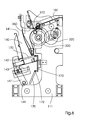
- the feeder 100 shown in FIGS. 1 and 2 has four stack supports 101, 102, 103, 104 for sheets. As can be seen in Fig. 6, located below the stack supports 101, 102, 103, 104 of the collection channel 140, which extends over the entire length of the investor.
- the lowermost sheet in a stack on a stack support 101, 102, 103, 104 is detected by a suction air gripper 370 near the leading edge, sucked by negative pressure, and deflected downward by the suction air gripper 370.
- the overlying sheets are restrained by the retaining finger 360, which is pivoted under the stack of sheets for this purpose.
- Grippers 236, 237 mounted on gripper discs 231, 233, which are part of the gripper drum 231, 232, grip the deflected leading edge of the lower sheet and pull the sheet from the underside of the stack, over the guide surface 130 in FIG Direction collecting duct 140.
- the sheet is supported by the gripper discs 231, 233.
- drivers 170 are arranged, which are pivotally attached to a chain 173 about a hinge 172.
- the free end of the driver 170 extends in a gap 142 in the guide surface 141 of the collecting channel 140.
- the guide surface 141 of the collecting channel 140 is movably mounted on guide rods 143 and can by means of the driven lever 147, which is pivotally mounted about the pivot point 149, along the Guide rods 143 are moved so that the width of the collecting channel 140 can be changed. This width adjustment is done automatically based on data regarding the thickness of the stack of sheets to be collected in the collection channel 140.
- the housing of the feeder 100 is essentially formed by side walls 111, 112 and cross braces 120, which connect the side walls 111, 112 together.
- a receiving plate 160 is also arranged between the side walls 111, 112 of the feeder housing.
- the cross brace 120 and the receiving plate 160 are advantageously releasably bolted to the side walls 111, 112.
- the receiving plate 160 shown in FIG. 2 has receiving locations 161, 162 for gripper shaft units 200 and a receiving space 165 for a camshaft unit 300.
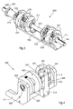
- the gripper shaft unit 200 is shown in FIG. Accordingly, the gripper shaft unit 200 consists of a bottom plate 205 to which side walls 211, 212 are fixed, wherein in the side walls 211, 212, the gripper shaft 220 is rotatably mounted. In addition, the gripper shaft 220 is supported by the supports 213, 214. Two gripper drums 230, 232 together with the gripper discs 231, 233 are mounted on the gripper shaft 220. These are essentially disc-shaped and are attached laterally to the gripper shaft 220. In addition, located on the gripper shaft 220, a gear 250.
- the ends of the gripper shaft 220 have grooves 241, 242 on.
- a coupling 270 see FIG. 5
- adjacent gripper shafts 220, 220 ', 220 can be connected to one another, so that these gripper shafts 220, 220', 220" can be driven together.
- Such Gripper shaft unit 200 may be assembled outside the feeder to be subsequently installed on the corresponding receiving space 161, 162 in the feeder.
- Fig. 4 shows a cam shaft unit.
- the cam shaft unit 300 also has two side walls 311, 312 and a bottom plate 305 connecting the two side walls 311, 312.
- a gear 350 is mounted on the cam shaft 320.
- this gear 350 is a common gear having a plurality of teeth.
- This gear is engaged with the gear 250 of the gripper shaft unit. Thereby, the drive of the hook shaft unit 200 is transmitted to the cam shaft unit 300.
- 320 cam discs 331, 332 are arranged on the camshaft. These cams 331, 332 have inboard cam surfaces 333. Impellers 345 run along these cam surfaces 333. The impellers 345 are located at the end of levers 341, 342.
- the levers 341, 342 are pivotally mounted about a shaft 347, wherein the shaft 347 is mounted in a strut 314 which is fixed to the bottom plate 305 of the cam shaft unit 300. At the free end of the levers 341, 342 are not shown further lever that transmit the control movement of the cam surface 333 on the sheet separating elements 360, 370.
- the camshaft unit 300 can also be assembled separately from the feeder 100 and then completely installed at the receiving location 165 in the feeder. When installing the camshaft unit 300, the gear 350 comes into contact with the gear 250 of the gripper shaft unit 200. In a further embodiment, a coupling between the gears 250, 350 may additionally be provided. In an alternative embodiment, the drive is not transmitted via two gears 250, 350, but by other suitable means, such as a toothed belt drive.
- the elements of the second gripper shaft unit 200' correspond to the elements of the first gripper shaft unit 200, but are provided with one Comma (') marked.
- the first Gripper shaft 220 is coupled with a clutch 260 to the gripper shaft 220 ', the second gripper shaft unit 200.
- the gripper shaft 220 'of the second gripper shaft unit 200 is in turn coupled via a coupling 270 with the next gripper shaft 220 "in the adjacent feeder 102' through the side wall 111" and 112.
- the gripper shaft 220, 220 ', 220 can be arbitrarily extended via the coupling 260, 270.
- Like elements in the second feeder 102' are identified by the same reference numerals of the first feeder 100 with two additional reference marks (").
- a collecting unit 1000 is shown.
- This has a drive unit 400 with a drive 410, for example an electric motor, and a collecting duct 440, which adjoins a collecting duct 140 of an investor 100.
- the collection channel 440 of the drive unit has a Kanalverstelltechnik 450.
- the drive unit 400 has comparable cross struts 420 and side walls 411, 412. The cross braces 420 are aligned with the cross braces 120 of respective investors 100.
- the drive unit 400 is connected to only one feeder 100, but it will be understood that a larger number of identical investors 100, 100 "from the drive unit 400
- the collecting unit 1000 has a contact unit 500, which is arranged upstream of the feeder 100 in the collecting direction, which also has a channel 540 and channel adjustment units 550.
- the cross struts 520 are aligned with the cross struts 120 and 120, respectively 420 of the other units
- the application unit 500 is used for manual insertion of sheets or stacks of sheets.
- a cross section of an investor 100 is shown. Sheets which are stacked on a stack support 101 are fed by gripper drums via a guide plate 130 to the collection channel 140. Behind this first baffle 130 further baffles 151, 153 are arranged, which form a channel parallel to the collection channel 140, in which the individual sheets of this feeder 100 are pre-accelerated before they are fed to the collecting channel 140. In the baffles 151, 153 openings 152, 154 are provided by the sensors 155, 156 interact with each other. These are used for the capacitive measurement of the supplied sheet. The skilled person is clear that also here other sensors for determining the thickness of the sheet, such as ultrasound, transmitted light or other methods can be used.
- a double-sheet control can be carried out.
- a single sheet is requested from each stack support 101 of the feeder 100 in a test run, which is carried out in the set-up operation of a multi-pincer adhesive binder, and fed to the collecting duct 140.
- this arc passes through the sensors 155, 156, which thereby determine a value which is representative of the thickness of the supplied sheet.
- This value which is representative of the thickness of the sheet of each investor, is stored in the controller 199.
- a comparison measurement is also performed on each sheet fed to the collection channel 140 with the sensors 155, 156.
- the controller 199 If the value measured during the test operation deviates from the value of the sheets measured in normal operation, that is to say if it is substantially a multiple of the thickness value determined in the test run for this sheet from this feeder, the controller 199 is notified thereof is then a double or multiple sheet, which would be fed and thus a faulty book block is collected. The controller 199 may then take appropriate action to treat this erroneously collected book block 1 separately.
Landscapes
- Engineering & Computer Science (AREA)
- Mechanical Engineering (AREA)
- Sheets, Magazines, And Separation Thereof (AREA)
- Controlling Sheets Or Webs (AREA)
- Discharge By Other Means (AREA)
Applications Claiming Priority (2)
| Application Number | Priority Date | Filing Date | Title |
|---|---|---|---|
| ITMI20041408 ITMI20041408A1 (it) | 2004-07-14 | 2004-07-14 | Mettifoglio per addurre fogli |
| ITMI20041529 ITMI20041529A1 (it) | 2004-07-28 | 2004-07-28 | Dispositivo per la produzione di libri |
Publications (3)
| Publication Number | Publication Date |
|---|---|
| EP1619151A2 true EP1619151A2 (fr) | 2006-01-25 |
| EP1619151A3 EP1619151A3 (fr) | 2006-05-24 |
| EP1619151B1 EP1619151B1 (fr) | 2008-10-08 |
Family
ID=35005824
Family Applications (1)
| Application Number | Title | Priority Date | Filing Date |
|---|---|---|---|
| EP05106062A Expired - Lifetime EP1619151B1 (fr) | 2004-07-14 | 2005-07-05 | Margeur de feuilles pour faciliter le montage, le démontage et le remplacement des éléments |
Country Status (3)
| Country | Link |
|---|---|
| EP (1) | EP1619151B1 (fr) |
| AT (1) | ATE410386T1 (fr) |
| DE (1) | DE502005005588D1 (fr) |
Cited By (1)
| Publication number | Priority date | Publication date | Assignee | Title |
|---|---|---|---|---|
| EP1882655A1 (fr) * | 2006-07-26 | 2008-01-30 | Müller Martini Holding AG | Margeur |
Family Cites Families (5)
| Publication number | Priority date | Publication date | Assignee | Title |
|---|---|---|---|---|
| US3825247A (en) * | 1973-03-08 | 1974-07-23 | Harris Intertype Corp | Rotary gathering machine |
| JPS5185160A (fr) * | 1974-11-30 | 1976-07-26 | Hauni Werke Koerber & Co Kg | |
| DE4012084A1 (de) * | 1990-04-14 | 1991-10-17 | Kolbus Gmbh & Co Kg | Buchblocktransportkanal |
| US5586756A (en) * | 1994-11-02 | 1996-12-24 | Chang; Bobby | Dual mode pneumatic signature feeding spring and disabling apparatus |
| JP3278341B2 (ja) * | 1996-01-09 | 2002-04-30 | キヤノン株式会社 | ロ−ラ支持装置、シ−ト材給送装置及び原稿読取装置並びに画像記録装置 |
-
2005
- 2005-07-05 DE DE502005005588T patent/DE502005005588D1/de not_active Expired - Lifetime
- 2005-07-05 AT AT05106062T patent/ATE410386T1/de not_active IP Right Cessation
- 2005-07-05 EP EP05106062A patent/EP1619151B1/fr not_active Expired - Lifetime
Cited By (2)
| Publication number | Priority date | Publication date | Assignee | Title |
|---|---|---|---|---|
| EP1882655A1 (fr) * | 2006-07-26 | 2008-01-30 | Müller Martini Holding AG | Margeur |
| US8313101B2 (en) | 2006-07-26 | 2012-11-20 | Mueller Martini Holding Ag | Feeder |
Also Published As
| Publication number | Publication date |
|---|---|
| EP1619151B1 (fr) | 2008-10-08 |
| DE502005005588D1 (de) | 2008-11-20 |
| ATE410386T1 (de) | 2008-10-15 |
| EP1619151A3 (fr) | 2006-05-24 |
Similar Documents
| Publication | Publication Date | Title |
|---|---|---|
| EP1604931B1 (fr) | Dispositif pour traiter et/ou acheminer une bande de matière | |
| DE3033718A1 (de) | Vorrichtung zur verarbeitung oder behandlung von blattfoermigem material | |
| EP2030924A1 (fr) | Dispositif de traitement de produits imprimés | |
| EP2055483B1 (fr) | Dispositif d'affichage pour machines de traitement de supports d'impression | |
| DE102006016100A1 (de) | Pneumatisches Zuführ- und Vereinzelungssystem, Substrathandhabungssystem, Verfahren zum pneumatischen Zuführen und Vereinzeln flacher Substrate, Computerprogrammprodukt, Speichermedium | |
| DE102007053490A1 (de) | Sammelhefter mit variabler Kettenteilung | |
| EP1013589A2 (fr) | Plieuse à poches et procédé de contrôle du registre dans une plieuse à poches | |
| EP1619151B1 (fr) | Margeur de feuilles pour faciliter le montage, le démontage et le remplacement des éléments | |
| EP0453909A2 (fr) | Procédé pour le positionnement et le réglage d'une plieuse | |
| DE19955752B4 (de) | Motorgetriebene Förderbecher | |
| EP2762432B1 (fr) | Procédé de surveillance destiné à éviter la collision d'une poinçonneuse avec un balai de freinage | |
| DE10154506A1 (de) | Vorrichtung und Verfahren zur Bestimmung eines Überlapps einer Signatur | |
| DE102019128978A1 (de) | Bogenbearbeitungsmaschine mit zumindest einer Bogenablageeinrichtung und Verfahren zur Bogenablage | |
| DE10321267A1 (de) | Etikettendruckerappliziereinrichtung | |
| DE19844232C2 (de) | Vorrichtung zum Ansammeln und Ausrichten eines Stapels von Blättern eines Aufzeichnungsträgers | |
| EP2604438A2 (fr) | Procédé de commande du margeur d'une assembleuse | |
| DE29622921U1 (de) | Vereinzelungseinrichtung mit einstellbarem Vereinzelungsspalt | |
| EP1767478B1 (fr) | Élément d'entrainement et chaine collectrice | |
| DE10303374B4 (de) | Verfahren zum Steuern einer papierverarbeitenden Maschine | |
| EP2060519A2 (fr) | Dispositif pour former un courant d'articles plats se chevauchant | |
| EP3599103B1 (fr) | Assembleuse et brocheuse pour produits imprimés | |
| EP1084972A2 (fr) | Procédé et dispositif de collecte de données | |
| EP0989083B1 (fr) | Dispositif d'alimentation de feuilles pliées pour assembleuse | |
| DE102017012187B4 (de) | Bogenverarbeitende Maschine | |
| WO2022063428A1 (fr) | Dispositif et procédé pour empiler des documents de valeur, en particulier des billets de banque, ainsi que système de traitement de documents de valeur |
Legal Events
| Date | Code | Title | Description |
|---|---|---|---|
| PUAI | Public reference made under article 153(3) epc to a published international application that has entered the european phase |
Free format text: ORIGINAL CODE: 0009012 |
|
| AK | Designated contracting states |
Kind code of ref document: A2 Designated state(s): AT BE BG CH CY CZ DE DK EE ES FI FR GB GR HU IE IS IT LI LT LU LV MC NL PL PT RO SE SI SK TR |
|
| AX | Request for extension of the european patent |
Extension state: AL BA HR MK YU |
|
| PUAL | Search report despatched |
Free format text: ORIGINAL CODE: 0009013 |
|
| AK | Designated contracting states |
Kind code of ref document: A3 Designated state(s): AT BE BG CH CY CZ DE DK EE ES FI FR GB GR HU IE IS IT LI LT LU LV MC NL PL PT RO SE SI SK TR |
|
| AX | Request for extension of the european patent |
Extension state: AL BA HR MK YU |
|
| 17P | Request for examination filed |
Effective date: 20061124 |
|
| 17Q | First examination report despatched |
Effective date: 20061222 |
|
| AKX | Designation fees paid |
Designated state(s): AT BE BG CH CY CZ DE DK EE ES FI FR GB GR HU IE IS IT LI LT LU LV MC NL PL PT RO SE SI SK TR |
|
| GRAP | Despatch of communication of intention to grant a patent |
Free format text: ORIGINAL CODE: EPIDOSNIGR1 |
|
| RTI1 | Title (correction) |
Free format text: SHEET-FEEDER WITH FACILITATED REMOVAL, INSTALLATION OR REPLACEMENT OF COMPONENTS |
|
| GRAS | Grant fee paid |
Free format text: ORIGINAL CODE: EPIDOSNIGR3 |
|
| GRAA | (expected) grant |
Free format text: ORIGINAL CODE: 0009210 |
|
| AK | Designated contracting states |
Kind code of ref document: B1 Designated state(s): AT BE BG CH CY CZ DE DK EE ES FI FR GB GR HU IE IS IT LI LT LU LV MC NL PL PT RO SE SI SK TR |
|
| REG | Reference to a national code |
Ref country code: GB Ref legal event code: FG4D Free format text: NOT ENGLISH |
|
| REG | Reference to a national code |
Ref country code: CH Ref legal event code: EP |
|
| REG | Reference to a national code |
Ref country code: IE Ref legal event code: FG4D Free format text: LANGUAGE OF EP DOCUMENT: GERMAN |
|
| REF | Corresponds to: |
Ref document number: 502005005588 Country of ref document: DE Date of ref document: 20081120 Kind code of ref document: P |
|
| PG25 | Lapsed in a contracting state [announced via postgrant information from national office to epo] |
Ref country code: SI Free format text: LAPSE BECAUSE OF FAILURE TO SUBMIT A TRANSLATION OF THE DESCRIPTION OR TO PAY THE FEE WITHIN THE PRESCRIBED TIME-LIMIT Effective date: 20081008 |
|
| NLV1 | Nl: lapsed or annulled due to failure to fulfill the requirements of art. 29p and 29m of the patents act | ||
| PG25 | Lapsed in a contracting state [announced via postgrant information from national office to epo] |
Ref country code: LT Free format text: LAPSE BECAUSE OF FAILURE TO SUBMIT A TRANSLATION OF THE DESCRIPTION OR TO PAY THE FEE WITHIN THE PRESCRIBED TIME-LIMIT Effective date: 20081008 Ref country code: BG Free format text: LAPSE BECAUSE OF FAILURE TO SUBMIT A TRANSLATION OF THE DESCRIPTION OR TO PAY THE FEE WITHIN THE PRESCRIBED TIME-LIMIT Effective date: 20090108 Ref country code: ES Free format text: LAPSE BECAUSE OF FAILURE TO SUBMIT A TRANSLATION OF THE DESCRIPTION OR TO PAY THE FEE WITHIN THE PRESCRIBED TIME-LIMIT Effective date: 20090119 |
|
| PG25 | Lapsed in a contracting state [announced via postgrant information from national office to epo] |
Ref country code: IS Free format text: LAPSE BECAUSE OF FAILURE TO SUBMIT A TRANSLATION OF THE DESCRIPTION OR TO PAY THE FEE WITHIN THE PRESCRIBED TIME-LIMIT Effective date: 20090208 Ref country code: LV Free format text: LAPSE BECAUSE OF FAILURE TO SUBMIT A TRANSLATION OF THE DESCRIPTION OR TO PAY THE FEE WITHIN THE PRESCRIBED TIME-LIMIT Effective date: 20081008 Ref country code: NL Free format text: LAPSE BECAUSE OF FAILURE TO SUBMIT A TRANSLATION OF THE DESCRIPTION OR TO PAY THE FEE WITHIN THE PRESCRIBED TIME-LIMIT Effective date: 20081008 Ref country code: PT Free format text: LAPSE BECAUSE OF FAILURE TO SUBMIT A TRANSLATION OF THE DESCRIPTION OR TO PAY THE FEE WITHIN THE PRESCRIBED TIME-LIMIT Effective date: 20090218 Ref country code: PL Free format text: LAPSE BECAUSE OF FAILURE TO SUBMIT A TRANSLATION OF THE DESCRIPTION OR TO PAY THE FEE WITHIN THE PRESCRIBED TIME-LIMIT Effective date: 20081008 Ref country code: FI Free format text: LAPSE BECAUSE OF FAILURE TO SUBMIT A TRANSLATION OF THE DESCRIPTION OR TO PAY THE FEE WITHIN THE PRESCRIBED TIME-LIMIT Effective date: 20081008 |
|
| REG | Reference to a national code |
Ref country code: IE Ref legal event code: FD4D |
|
| PG25 | Lapsed in a contracting state [announced via postgrant information from national office to epo] |
Ref country code: DK Free format text: LAPSE BECAUSE OF FAILURE TO SUBMIT A TRANSLATION OF THE DESCRIPTION OR TO PAY THE FEE WITHIN THE PRESCRIBED TIME-LIMIT Effective date: 20081008 Ref country code: EE Free format text: LAPSE BECAUSE OF FAILURE TO SUBMIT A TRANSLATION OF THE DESCRIPTION OR TO PAY THE FEE WITHIN THE PRESCRIBED TIME-LIMIT Effective date: 20081008 Ref country code: IE Free format text: LAPSE BECAUSE OF FAILURE TO SUBMIT A TRANSLATION OF THE DESCRIPTION OR TO PAY THE FEE WITHIN THE PRESCRIBED TIME-LIMIT Effective date: 20081008 Ref country code: RO Free format text: LAPSE BECAUSE OF FAILURE TO SUBMIT A TRANSLATION OF THE DESCRIPTION OR TO PAY THE FEE WITHIN THE PRESCRIBED TIME-LIMIT Effective date: 20081008 |
|
| PLBE | No opposition filed within time limit |
Free format text: ORIGINAL CODE: 0009261 |
|
| STAA | Information on the status of an ep patent application or granted ep patent |
Free format text: STATUS: NO OPPOSITION FILED WITHIN TIME LIMIT |
|
| PG25 | Lapsed in a contracting state [announced via postgrant information from national office to epo] |
Ref country code: SE Free format text: LAPSE BECAUSE OF FAILURE TO SUBMIT A TRANSLATION OF THE DESCRIPTION OR TO PAY THE FEE WITHIN THE PRESCRIBED TIME-LIMIT Effective date: 20090108 Ref country code: CZ Free format text: LAPSE BECAUSE OF FAILURE TO SUBMIT A TRANSLATION OF THE DESCRIPTION OR TO PAY THE FEE WITHIN THE PRESCRIBED TIME-LIMIT Effective date: 20081008 |
|
| 26N | No opposition filed |
Effective date: 20090709 |
|
| PG25 | Lapsed in a contracting state [announced via postgrant information from national office to epo] |
Ref country code: SK Free format text: LAPSE BECAUSE OF FAILURE TO SUBMIT A TRANSLATION OF THE DESCRIPTION OR TO PAY THE FEE WITHIN THE PRESCRIBED TIME-LIMIT Effective date: 20081008 |
|
| BERE | Be: lapsed |
Owner name: HEIDELBERGER DRUCKMASCHINEN A.G. Effective date: 20090731 |
|
| PG25 | Lapsed in a contracting state [announced via postgrant information from national office to epo] |
Ref country code: MC Free format text: LAPSE BECAUSE OF NON-PAYMENT OF DUE FEES Effective date: 20090731 |
|
| REG | Reference to a national code |
Ref country code: CH Ref legal event code: PL |
|
| GBPC | Gb: european patent ceased through non-payment of renewal fee |
Effective date: 20090705 |
|
| REG | Reference to a national code |
Ref country code: FR Ref legal event code: ST Effective date: 20100331 |
|
| PG25 | Lapsed in a contracting state [announced via postgrant information from national office to epo] |
Ref country code: FR Free format text: LAPSE BECAUSE OF NON-PAYMENT OF DUE FEES Effective date: 20090731 Ref country code: LI Free format text: LAPSE BECAUSE OF NON-PAYMENT OF DUE FEES Effective date: 20090731 Ref country code: CH Free format text: LAPSE BECAUSE OF NON-PAYMENT OF DUE FEES Effective date: 20090731 |
|
| PG25 | Lapsed in a contracting state [announced via postgrant information from national office to epo] |
Ref country code: GB Free format text: LAPSE BECAUSE OF NON-PAYMENT OF DUE FEES Effective date: 20090705 |
|
| PG25 | Lapsed in a contracting state [announced via postgrant information from national office to epo] |
Ref country code: BE Free format text: LAPSE BECAUSE OF NON-PAYMENT OF DUE FEES Effective date: 20090731 |
|
| PG25 | Lapsed in a contracting state [announced via postgrant information from national office to epo] |
Ref country code: GR Free format text: LAPSE BECAUSE OF FAILURE TO SUBMIT A TRANSLATION OF THE DESCRIPTION OR TO PAY THE FEE WITHIN THE PRESCRIBED TIME-LIMIT Effective date: 20090109 |
|
| PG25 | Lapsed in a contracting state [announced via postgrant information from national office to epo] |
Ref country code: AT Free format text: LAPSE BECAUSE OF NON-PAYMENT OF DUE FEES Effective date: 20090705 |
|
| PGFP | Annual fee paid to national office [announced via postgrant information from national office to epo] |
Ref country code: DE Payment date: 20100731 Year of fee payment: 6 Ref country code: IT Payment date: 20100721 Year of fee payment: 6 |
|
| PG25 | Lapsed in a contracting state [announced via postgrant information from national office to epo] |
Ref country code: LU Free format text: LAPSE BECAUSE OF NON-PAYMENT OF DUE FEES Effective date: 20090705 |
|
| PG25 | Lapsed in a contracting state [announced via postgrant information from national office to epo] |
Ref country code: HU Free format text: LAPSE BECAUSE OF FAILURE TO SUBMIT A TRANSLATION OF THE DESCRIPTION OR TO PAY THE FEE WITHIN THE PRESCRIBED TIME-LIMIT Effective date: 20090409 |
|
| PG25 | Lapsed in a contracting state [announced via postgrant information from national office to epo] |
Ref country code: TR Free format text: LAPSE BECAUSE OF FAILURE TO SUBMIT A TRANSLATION OF THE DESCRIPTION OR TO PAY THE FEE WITHIN THE PRESCRIBED TIME-LIMIT Effective date: 20081008 |
|
| PG25 | Lapsed in a contracting state [announced via postgrant information from national office to epo] |
Ref country code: CY Free format text: LAPSE BECAUSE OF FAILURE TO SUBMIT A TRANSLATION OF THE DESCRIPTION OR TO PAY THE FEE WITHIN THE PRESCRIBED TIME-LIMIT Effective date: 20081008 |
|
| PG25 | Lapsed in a contracting state [announced via postgrant information from national office to epo] |
Ref country code: DE Free format text: LAPSE BECAUSE OF NON-PAYMENT OF DUE FEES Effective date: 20120201 |
|
| REG | Reference to a national code |
Ref country code: DE Ref legal event code: R119 Ref document number: 502005005588 Country of ref document: DE Effective date: 20120201 |
|
| PG25 | Lapsed in a contracting state [announced via postgrant information from national office to epo] |
Ref country code: IT Free format text: LAPSE BECAUSE OF NON-PAYMENT OF DUE FEES Effective date: 20110705 |