EP1619384B1 - Fuel injector provided with a high flexibility plunger - Google Patents
Fuel injector provided with a high flexibility plunger Download PDFInfo
- Publication number
- EP1619384B1 EP1619384B1 EP05106781A EP05106781A EP1619384B1 EP 1619384 B1 EP1619384 B1 EP 1619384B1 EP 05106781 A EP05106781 A EP 05106781A EP 05106781 A EP05106781 A EP 05106781A EP 1619384 B1 EP1619384 B1 EP 1619384B1
- Authority
- EP
- European Patent Office
- Prior art keywords
- plunger
- injector
- rod
- fuel
- armature
- Prior art date
- Legal status (The legal status is an assumption and is not a legal conclusion. Google has not performed a legal analysis and makes no representation as to the accuracy of the status listed.)
- Expired - Lifetime
Links
Images


Classifications
-
- F—MECHANICAL ENGINEERING; LIGHTING; HEATING; WEAPONS; BLASTING
- F02—COMBUSTION ENGINES; HOT-GAS OR COMBUSTION-PRODUCT ENGINE PLANTS
- F02M—SUPPLYING COMBUSTION ENGINES IN GENERAL WITH COMBUSTIBLE MIXTURES OR CONSTITUENTS THEREOF
- F02M61/00—Fuel-injectors not provided for in groups F02M39/00 - F02M57/00 or F02M67/00
- F02M61/16—Details not provided for in, or of interest apart from, the apparatus of groups F02M61/02 - F02M61/14
-
- F—MECHANICAL ENGINEERING; LIGHTING; HEATING; WEAPONS; BLASTING
- F02—COMBUSTION ENGINES; HOT-GAS OR COMBUSTION-PRODUCT ENGINE PLANTS
- F02M—SUPPLYING COMBUSTION ENGINES IN GENERAL WITH COMBUSTIBLE MIXTURES OR CONSTITUENTS THEREOF
- F02M51/00—Fuel-injection apparatus characterised by being operated electrically
- F02M51/06—Injectors peculiar thereto with means directly operating the valve needle
- F02M51/061—Injectors peculiar thereto with means directly operating the valve needle using electromagnetic operating means
- F02M51/0625—Injectors peculiar thereto with means directly operating the valve needle using electromagnetic operating means characterised by arrangement of mobile armatures
- F02M51/0664—Injectors peculiar thereto with means directly operating the valve needle using electromagnetic operating means characterised by arrangement of mobile armatures having a cylindrically or partly cylindrically shaped armature, e.g. entering the winding; having a plate-shaped or undulated armature entering the winding
- F02M51/0671—Injectors peculiar thereto with means directly operating the valve needle using electromagnetic operating means characterised by arrangement of mobile armatures having a cylindrically or partly cylindrically shaped armature, e.g. entering the winding; having a plate-shaped or undulated armature entering the winding the armature having an elongated valve body attached thereto
-
- F—MECHANICAL ENGINEERING; LIGHTING; HEATING; WEAPONS; BLASTING
- F02—COMBUSTION ENGINES; HOT-GAS OR COMBUSTION-PRODUCT ENGINE PLANTS
- F02M—SUPPLYING COMBUSTION ENGINES IN GENERAL WITH COMBUSTIBLE MIXTURES OR CONSTITUENTS THEREOF
- F02M61/00—Fuel-injectors not provided for in groups F02M39/00 - F02M57/00 or F02M67/00
- F02M61/04—Fuel-injectors not provided for in groups F02M39/00 - F02M57/00 or F02M67/00 having valves, e.g. having a plurality of valves in series
- F02M61/10—Other injectors with elongated valve bodies, i.e. of needle-valve type
-
- F—MECHANICAL ENGINEERING; LIGHTING; HEATING; WEAPONS; BLASTING
- F02—COMBUSTION ENGINES; HOT-GAS OR COMBUSTION-PRODUCT ENGINE PLANTS
- F02M—SUPPLYING COMBUSTION ENGINES IN GENERAL WITH COMBUSTIBLE MIXTURES OR CONSTITUENTS THEREOF
- F02M61/00—Fuel-injectors not provided for in groups F02M39/00 - F02M57/00 or F02M67/00
- F02M61/16—Details not provided for in, or of interest apart from, the apparatus of groups F02M61/02 - F02M61/14
- F02M61/166—Selection of particular materials
Definitions
- the present invention relates to a fuel injector.
- An electromagnetic fuel injector normally comprises a cylindrical tubular body with a central channel which performs the function of a fuel duct and ends with an injection jet controlled by an injection-valve operated by an electromagnetic actuator; in particular, the injection valve is provided with a plunger, which is rigidly connected to a mobile armature of the electromagnetic actuator so as to be displaced by the action of the electromagnetic actuator between a closed position and an open position of the injection jet against the action of a spring which tends to hold the plunger in the closed position.
- the dimensions and positioning of the plunger, of the valve seat and of the armature must be very accurate. Indeed, if structural tolerances are relatively large, when the armature strikes against a fixed armature of the electromagnet, transverse forces may arise which are transmitted to the plunger and are in part dissipated at the level of the coupling between the end portion of the plunger and the guide portion of the valve seat; it has been observed experimentally that if such forces exceed a certain value, localised wear phenomena may occur on the plunger and/or the guide portion of the valve seat with a consequent reduction in the service life of the injector.
- US4030668A1 discloses an electromagnetically operated fuel injection valve comprising narrow arcuate slots etched through a thin spray disc located downstream of a metering orifice and upstream thereof comprises a ball seat for providing a circular edge contact with a slightly smaller ball valve carried on the free end of a flexible stem.
- DE10148824A1 discloses a fuel injection valve having a magnetic coil and a cooperating armature for axial movement of a spring-biased valve needle provided with a valve closure cooperating with a valve seat, an inner pole and an outer pole providing a magnetic circuit together with the magnetic coil and a central fuel feed; A sleeve is inserted in the central fuel feed to provide a fuel flow path with a length and diameter such that the characteristic oscillation frequency of the supplied fuel is matched to the closure intervals of the fuel injection valve.
- the object of the present invention is to provide a fuel injector which does not exhibit the above-stated disadvantages and, in particular, is simple and economic to produce.
- the present invention provides a fuel injector as specified in the attached claims.
- FIG 1 denotes the overall fuel injector, which exhibits a substantially cylindrical symmetry around a longitudinal axis 2 and is capable of being operated to inject fuel from an injection jet 3 which opens directly into an explosion chamber (not shown) of a cylinder.
- the injector 1 comprises a supporting body 4, which has a tubular cylindrical shape of variable cross-section along the longitudinal axis 2 and comprises a supply channel 5 extending along the entire length of said supporting body 4 to supply the pressurised fuel to the injection jet 3.
- the supporting body 4 accommodates an electromagnetic actuator 6 at the level of an upper portion thereof and an injection valve 7 at the level of a lower portion thereof; in service, the injection valve 7 is actuated by the electromagnetic actuator 6 to control the flow of fuel through the injection jet 3, which is provided at the level of said injection valve 7.
- the electromagnetic actuator 6 comprises an electromagnet 8, which is accommodated in fixed position within the supporting body 4 and which, when energised, is capable of displacing a mobile armature 9 of ferromagnetic material along the axis 2 from a closed position to an open position of the injection valve 7 against the action of a spring 10 which tends to hold the mobile armature 9 in the closed position of the injection valve 7.
- the electromagnet 8 comprises a coil 11, which is supplied with electricity by an electronic control unit (not shown) and is accommodated outside the supporting body 4, and a fixed magnetic armature 12, which is accommodated inside the supporting body 4 and has a central hole 13 to allow the fuel to flow towards the injection jet 3.
- an abutment member 14 is driven into a fixed position, which abutment member is of a tubular cylindrical shape (optionally open along a generating line) to allow the fuel to flow towards the injection jet 3 and is capable of holding the spring 10 in a compressed state against the mobile armature 9.
- the mobile armature 9 is part of a mobile assembly which moreover comprises a poppet or plunger 15 having an upper portion integral with the mobile armature 9 and a lower portion which cooperates with a valve seat 16 (shown in Figure 2 ) of the injection valve 7 to control the flow of fuel through the injection jet 3 in known manner.
- a poppet or plunger 15 having an upper portion integral with the mobile armature 9 and a lower portion which cooperates with a valve seat 16 (shown in Figure 2 ) of the injection valve 7 to control the flow of fuel through the injection jet 3 in known manner.
- the valve seat 16 is defined by a sealing member 17, which is disc-shaped, seals the bottom of the supply channel 5 of the supporting body 4, and is passed through by the injection jet 3.
- a guide member 18 rises up from the discoid sealing member 17, which guide member is tubular in shape, receives within it the plunger 15 to define a lower guide for said plunger 15 and has an external diameter smaller than the internal diameter of the supply channel 5 of the supporting body 4, so as to define an external annular channel 19 through which the pressurised fuel can flow.
- the guide member 18 has an external diameter which is equal to the internal diameter of the supply channel 5 and has flattened portions on the outside so as to create passages for the fuel.
- through-holes 20 In the lower part of the guide member 18, there are provided four through-holes 20 (only two of which are shown in Figure 2 ), which are arranged perpendicularly to the longitudinal axis 2 and open into the valve seat 16 to allow the pressurised fuel to flow towards said valve seat 16.
- the through-holes 20 may be arranged offset relative to the longitudinal axis 2 such that they do not converge towards said longitudinal axis 2 and, in service, they impart a swirling flow to the respective streams of fuel.
- the plunger 15 ends in a sealing head 21, substantially spherical in shape, which is capable of resting in sealing manner against the valve seat 16. Furthermore, the sealing head 21 rests so as to slide on a cylindrical internal surface 22 of the guide member 18, so that it will be guided as it moves along the longitudinal axis 2.
- the mobile armature 9 is a monolithic body and comprises an annular member 23 and a discoid member 24, which closes the bottom of the annular member 23 and has a central through-hole 25 capable of receiving an upper portion of the plunger 15 and a plurality of peripheral through-holes 26 (only two of which are shown in Figure 3 ) capable of allowing the fuel to flow towards the injection jet 3.
- a central portion of the discoid member 24 is suitably shaped to receive a lower end of the spring 10 and hold it in position.
- the plunger 15 is preferably made integral with the discoid member 24 of the mobile armature 9 by means of an annular weld 27.
- Figure 4 shows an alternative embodiment of the mobile armature 9; as shown in Figure 4 , the annular member 23 is distinct from the discoid member 24 and is connected rigidly to said discoid member 24 by means of an annular weld 28.
- the annular member 23 of the mobile armature 9 has an external diameter substantially identical to the internal diameter of the corresponding portion of the supply channel 5 of the supporting body 4; in this manner, the mobile armature 9 can slide relative to the supporting body 4 along the longitudinal axis 2, but cannot make any movement transverse to the longitudinal axis 2, relative to the supporting body 4. Since the plunger 15 is rigidly connected to the mobile armature 9, it is clear that the mobile armature 9 also acts as an upper guide for the plunger 15; as a result, the plunger 15 is guided at the top by the mobile armature 9 and at the bottom by the guide member 18.
- an antirebound device is attached to the lower face of the discoid member 24 of the mobile armature 9, which antirebound device is capable of damping the rebound of the sealing head 21 of the plunger 15 against the valve seat 16 when the plunger 15 moves from the open position to the closed position of the injection valve 7.
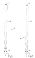
- Figure 5 shows the plunger 15; it can be seen that the plunger 15 has an upper rod 29 with cylindrical symmetry, to which is connected the substantially spherical sealing head 21 by means of an annular weld 30.
- the rod 29 of the plunger 15 is of different diameters along its length; in particular, the end portions of the rod 29 are of a larger diameter relative to the central portion of the rod 29.
- the rod 29 of the plunger 15 is of a perfectly cylindrical shape with a constant diameter along its entire length.
- the mobile armature 9 When the electromagnet 8 is energised, the mobile armature 9 is magnetically attracted by the fixed magnetic armature 12 against the resilient force of the spring 10 and the mobile armature 9 moves upwards together with the plunger 15 until it comes into contact with said fixed magnetic armature 12; in this situation, the sealing head 21 of the plunger 15 is lifted relative to the valve seat 16 of the injection valve 7 and the pressurised fuel can flow through the injection jet 3.
- the rod 29 of the plunger 15 in such a manner as to impart relatively high flexibility to said rod 29 (or in other words relatively low flexural rigidity) which flexibility is certainly greater than that normally present in known, currently commercially available injectors; it has in fact been observed that increasing the flexibility of the rod 29 reduces the transmission of transverse stresses from the mobile armature 9 to the sealing head 21. In other words, if the rod 29 of the plunger 15 is sufficiently flexible, the transmission of transverse stresses from the mobile armature 9 to the sealing head 21 is reduced and it is then no longer necessary to precision machine the components with the aim of achieving very tight structural tolerances.
- rod 29 of plunger 15 must not be too flexible, because if it were too flexible it would not be capable of ensuring rapid and precise operation of the injection valve 7.
- a flexibility parameter P f which is a reliable indicator of the flexibility of the rod 29 and has the dimensions of a pressure (N/mm 2 ). It is important to note that, since the flexibility parameter P f has the dimensions of a pressure (N/mm 2 ), said flexibility parameter P f may be traced back to the phenomenon of contact/impact pressure wear between the sealing head 21 and the internal surface of the guide member 18.
- the flexibility parameter P f In order to achieve the desired effect of limiting the transmission of the transverse stresses from the mobile armature 9 to the sealing head 21 without however prejudicing the performance of the injection valve 7, the flexibility parameter P f must be between 1 and 2 N/mm 2 .
- the flexibility parameter P f is preferably between 1.3 and 1.5 N/mm 2 and is substantially equal to approx 1.4 N/mm 2 .
- the transverse section of the rod 29 may be varied, a material of greater or lesser elasticity may be used to produce the rod 29, the cross-sectional shape of the rod 29 may be varied.
Landscapes
- Engineering & Computer Science (AREA)
- Chemical & Material Sciences (AREA)
- Combustion & Propulsion (AREA)
- Mechanical Engineering (AREA)
- General Engineering & Computer Science (AREA)
- Physics & Mathematics (AREA)
- Electromagnetism (AREA)
- Fuel-Injection Apparatus (AREA)
Applications Claiming Priority (1)
| Application Number | Priority Date | Filing Date | Title |
|---|---|---|---|
| IT000512A ITTO20040512A1 (it) | 2004-07-23 | 2004-07-23 | Iniettore di carburante provvisto di spillo ad elevata flessibilita' |
Publications (3)
| Publication Number | Publication Date |
|---|---|
| EP1619384A2 EP1619384A2 (en) | 2006-01-25 |
| EP1619384A3 EP1619384A3 (en) | 2006-05-24 |
| EP1619384B1 true EP1619384B1 (en) | 2012-09-19 |
Family
ID=35335754
Family Applications (1)
| Application Number | Title | Priority Date | Filing Date |
|---|---|---|---|
| EP05106781A Expired - Lifetime EP1619384B1 (en) | 2004-07-23 | 2005-07-22 | Fuel injector provided with a high flexibility plunger |
Country Status (5)
| Country | Link |
|---|---|
| US (1) | US20060016916A1 (it) |
| EP (1) | EP1619384B1 (it) |
| CN (1) | CN1727666B (it) |
| BR (1) | BRPI0502911B1 (it) |
| IT (1) | ITTO20040512A1 (it) |
Cited By (1)
| Publication number | Priority date | Publication date | Assignee | Title |
|---|---|---|---|---|
| WO2024121302A1 (en) * | 2022-12-07 | 2024-06-13 | Phinia Delphi Luxembourg Sarl | Fuel injector |
Families Citing this family (51)
| Publication number | Priority date | Publication date | Assignee | Title |
|---|---|---|---|---|
| US7631822B2 (en) * | 2004-09-10 | 2009-12-15 | Fellowes Inc. | Shredder with thickness detector |
| JP4211814B2 (ja) * | 2006-07-13 | 2009-01-21 | 株式会社日立製作所 | 電磁式燃料噴射弁 |
| DE602006005385D1 (de) | 2006-12-12 | 2009-04-09 | Magneti Marelli Powertrain Spa | Elektromagnetisches Kraftstoffeinspritzventil für eine Brennkraftmaschine mit Direkteinspritzung |
| US8387599B2 (en) | 2008-01-07 | 2013-03-05 | Mcalister Technologies, Llc | Methods and systems for reducing the formation of oxides of nitrogen during combustion in engines |
| US8635985B2 (en) | 2008-01-07 | 2014-01-28 | Mcalister Technologies, Llc | Integrated fuel injectors and igniters and associated methods of use and manufacture |
| US7628137B1 (en) | 2008-01-07 | 2009-12-08 | Mcalister Roy E | Multifuel storage, metering and ignition system |
| US8074625B2 (en) * | 2008-01-07 | 2011-12-13 | Mcalister Technologies, Llc | Fuel injector actuator assemblies and associated methods of use and manufacture |
| US8413634B2 (en) * | 2008-01-07 | 2013-04-09 | Mcalister Technologies, Llc | Integrated fuel injector igniters with conductive cable assemblies |
| US8225768B2 (en) * | 2008-01-07 | 2012-07-24 | Mcalister Technologies, Llc | Integrated fuel injector igniters suitable for large engine applications and associated methods of use and manufacture |
| US8561598B2 (en) * | 2008-01-07 | 2013-10-22 | Mcalister Technologies, Llc | Method and system of thermochemical regeneration to provide oxygenated fuel, for example, with fuel-cooled fuel injectors |
| US8365700B2 (en) * | 2008-01-07 | 2013-02-05 | Mcalister Technologies, Llc | Shaping a fuel charge in a combustion chamber with multiple drivers and/or ionization control |
| IT1394019B1 (it) * | 2009-05-06 | 2012-05-25 | Magneti Marelli Spa | Iniettore elettromagnetico di carburante con smorzamento idraulico |
| DE102009024595A1 (de) * | 2009-06-10 | 2011-03-24 | Continental Automotive Gmbh | Einspritzventil mit Übertragungseinheit |
| DE102009024596A1 (de) | 2009-06-10 | 2011-04-07 | Continental Automotive Gmbh | Einspritzventil mit Übertragungseinheit |
| JP5563660B2 (ja) * | 2009-08-27 | 2014-07-30 | マクアリスター テクノロジーズ エルエルシー | セラミック絶縁体並びにその使用及び製造方法 |
| CA2772044C (en) | 2009-08-27 | 2013-04-16 | Mcalister Technologies, Llc | Shaping a fuel charge in a combustion chamber with multiple drivers and/or ionization control |
| KR20120086375A (ko) | 2009-12-07 | 2012-08-02 | 맥알리스터 테크놀로지즈 엘엘씨 | 연료 인젝터 및 점화기를 위한 적응 제어 시스템 |
| KR101364416B1 (ko) | 2009-12-07 | 2014-02-17 | 맥알리스터 테크놀로지즈 엘엘씨 | 대형 엔진 적용에 적합한 일체식 연료 인젝터 점화기 및 연관된 이용 및 제조방법 |
| WO2011100701A2 (en) | 2010-02-13 | 2011-08-18 | Mcalister Roy E | Fuel injector assemblies having acoustical force modifiers and associated methods of use and manufacture |
| EP2534347B1 (en) | 2010-02-13 | 2016-05-04 | McAlister, Roy Edward | Methods and systems for adaptively cooling combustion chambers in engines |
| US20110297753A1 (en) | 2010-12-06 | 2011-12-08 | Mcalister Roy E | Integrated fuel injector igniters configured to inject multiple fuels and/or coolants and associated methods of use and manufacture |
| IT1399312B1 (it) | 2010-04-07 | 2013-04-16 | Magneti Marelli Spa | Metodo di controllo di un iniettore elettromagnetico di carburante |
| IT1399311B1 (it) | 2010-04-07 | 2013-04-16 | Magneti Marelli Spa | Metodo per determinare l'istante di chiusura di un iniettore elettromagnetico di carburante |
| US8528519B2 (en) | 2010-10-27 | 2013-09-10 | Mcalister Technologies, Llc | Integrated fuel injector igniters suitable for large engine applications and associated methods of use and manufacture |
| IT1402820B1 (it) | 2010-11-10 | 2013-09-27 | Magneti Marelli Spa | Metodo per determinare la legge di iniezione di un iniettore di carburante |
| IT1402821B1 (it) * | 2010-11-10 | 2013-09-27 | Magneti Marelli Spa | Metodo per determinare la legge di iniezione di un iniettore di carburante utilizzando un banco a rulli |
| US8091528B2 (en) | 2010-12-06 | 2012-01-10 | Mcalister Technologies, Llc | Integrated fuel injector igniters having force generating assemblies for injecting and igniting fuel and associated methods of use and manufacture |
| US8820275B2 (en) | 2011-02-14 | 2014-09-02 | Mcalister Technologies, Llc | Torque multiplier engines |
| US8919377B2 (en) | 2011-08-12 | 2014-12-30 | Mcalister Technologies, Llc | Acoustically actuated flow valve assembly including a plurality of reed valves |
| CN103890343B (zh) | 2011-08-12 | 2015-07-15 | 麦卡利斯特技术有限责任公司 | 用于改进的发动机冷却及能量产生的系统和方法 |
| JP2013072298A (ja) * | 2011-09-27 | 2013-04-22 | Hitachi Automotive Systems Ltd | 燃料噴射弁 |
| CN102748481A (zh) * | 2012-07-12 | 2012-10-24 | 宁波舜田良源油嘴油泵有限公司 | 一种用于scr系统尿素喷射阀及其激光焊接方法 |
| US8746197B2 (en) | 2012-11-02 | 2014-06-10 | Mcalister Technologies, Llc | Fuel injection systems with enhanced corona burst |
| US9169821B2 (en) | 2012-11-02 | 2015-10-27 | Mcalister Technologies, Llc | Fuel injection systems with enhanced corona burst |
| US9169814B2 (en) | 2012-11-02 | 2015-10-27 | Mcalister Technologies, Llc | Systems, methods, and devices with enhanced lorentz thrust |
| US9200561B2 (en) | 2012-11-12 | 2015-12-01 | Mcalister Technologies, Llc | Chemical fuel conditioning and activation |
| US9194337B2 (en) | 2013-03-14 | 2015-11-24 | Advanced Green Innovations, LLC | High pressure direct injected gaseous fuel system and retrofit kit incorporating the same |
| ITBO20130169A1 (it) | 2013-04-17 | 2014-10-18 | Magneti Marelli Spa | Iniettore elettromagnetico di carburante con dispositivo frenante |
| EP2975256B1 (en) | 2014-07-14 | 2016-07-27 | Magneti Marelli S.p.A. | Electromagnetic fuel injector with hydraulic braking device |
| DE102014226407A1 (de) * | 2014-12-18 | 2016-06-23 | Robert Bosch Gmbh | Einspritzdüse für Kraftstoffe |
| JP6488134B2 (ja) * | 2015-01-26 | 2019-03-20 | 日立オートモティブシステムズ株式会社 | 燃料噴射弁 |
| ITBO20150236A1 (it) | 2015-05-05 | 2016-11-05 | Magneti Marelli Spa | Iniettore elettromagnetico di carburante con gola anulare disposta in corrispondenza della saldatura di una prolunga |
| ITBO20150235A1 (it) | 2015-05-05 | 2016-11-05 | Magneti Marelli Spa | Iniettore elettromagnetico di carburante con ottimizzazione delle saldature |
| ITUB20152480A1 (it) * | 2015-07-24 | 2017-01-24 | Magneti Marelli Spa | Iniettore elettromagnetico di carburante con testa di otturazione sferica in materiale ceramico |
| IT201800005760A1 (it) | 2018-05-28 | 2019-11-28 | Metodo per determinare un istante di chiusura di un iniettore elettromagnetico di carburante | |
| IT201800005765A1 (it) | 2018-05-28 | 2019-11-28 | Metodo per determinare un tempo di apertura di un iniettore elettromagnetico di carburante | |
| IT202000004003A1 (it) | 2020-02-26 | 2021-08-26 | Marelli Europe Spa | Metodo di verifica della ripetibilita' dell'iniezione in un iniettore elettromagnetico di carburante e corrispondente banco di prova |
| CN113250878B (zh) * | 2021-06-18 | 2022-08-16 | 中国北方发动机研究所(天津) | 一种共轨喷油器控制柱塞部件 |
| IT202300000021A1 (it) | 2023-01-03 | 2024-07-03 | Marelli Europe Spa | Metodo di diagnosi di un dispositivo elettromeccanico con attuazione elettromagnetica |
| IT202400004939A1 (it) | 2024-03-06 | 2025-09-06 | Marelli Europe Spa | Iniettore elettromagnetico di carburante |
| EP4491865B1 (en) | 2023-07-10 | 2025-11-26 | Marelli Europe S.p.A. | Electromagnetic fuel injector |
Citations (1)
| Publication number | Priority date | Publication date | Assignee | Title |
|---|---|---|---|---|
| DE10148824A1 (de) * | 2001-10-04 | 2003-04-10 | Bosch Gmbh Robert | Brennstoffeinspritzventil |
Family Cites Families (10)
| Publication number | Priority date | Publication date | Assignee | Title |
|---|---|---|---|---|
| NL7607080A (nl) * | 1976-06-28 | 1977-12-30 | Holec Nv | Inrichting voor het afgeven van brandstof aan een verbrandingsmotor. |
| US4030668A (en) * | 1976-06-17 | 1977-06-21 | The Bendix Corporation | Electromagnetically operated fuel injection valve |
| DE3124854C2 (de) * | 1981-06-24 | 1985-03-14 | Reinhard 8057 Eching Mühlbauer | Hochdruckeinspritzsystem mit Ultraschall-Zerstäubung |
| GB9301793D0 (en) * | 1993-01-29 | 1993-03-17 | Lucas Ind Plc | Fuel injection nozzle |
| US5544816A (en) * | 1994-08-18 | 1996-08-13 | Siemens Automotive L.P. | Housing for coil of solenoid-operated fuel injector |
| DE19547406B4 (de) * | 1995-12-19 | 2007-10-31 | Robert Bosch Gmbh | Brennstoffeinspritzventil |
| DE19625059A1 (de) * | 1996-06-22 | 1998-01-02 | Bosch Gmbh Robert | Einspritzventil, insbesondere zum direkten Einspritzen von Kraftstoff in einen Brennraum eines Verbrennungsmotors |
| US5921475A (en) * | 1997-08-07 | 1999-07-13 | Ford Motor Company | Automotive fuel injector |
| DE10237003A1 (de) * | 2002-08-13 | 2004-03-18 | Robert Bosch Gmbh | Kraftstoffeinspritzventil für Brennkraftmaschinen |
| JP4078165B2 (ja) * | 2002-09-18 | 2008-04-23 | 株式会社日立製作所 | 燃料噴射弁 |
-
2004
- 2004-07-23 IT IT000512A patent/ITTO20040512A1/it unknown
-
2005
- 2005-07-20 BR BRPI0502911-2A patent/BRPI0502911B1/pt not_active IP Right Cessation
- 2005-07-22 EP EP05106781A patent/EP1619384B1/en not_active Expired - Lifetime
- 2005-07-22 US US11/188,096 patent/US20060016916A1/en not_active Abandoned
- 2005-07-25 CN CN2005100849476A patent/CN1727666B/zh not_active Expired - Fee Related
Patent Citations (1)
| Publication number | Priority date | Publication date | Assignee | Title |
|---|---|---|---|---|
| DE10148824A1 (de) * | 2001-10-04 | 2003-04-10 | Bosch Gmbh Robert | Brennstoffeinspritzventil |
Cited By (1)
| Publication number | Priority date | Publication date | Assignee | Title |
|---|---|---|---|---|
| WO2024121302A1 (en) * | 2022-12-07 | 2024-06-13 | Phinia Delphi Luxembourg Sarl | Fuel injector |
Also Published As
| Publication number | Publication date |
|---|---|
| US20060016916A1 (en) | 2006-01-26 |
| CN1727666A (zh) | 2006-02-01 |
| BRPI0502911A (pt) | 2006-03-07 |
| CN1727666B (zh) | 2010-12-01 |
| ITTO20040512A1 (it) | 2004-10-23 |
| EP1619384A2 (en) | 2006-01-25 |
| EP1619384A3 (en) | 2006-05-24 |
| BRPI0502911B1 (pt) | 2018-05-02 |
Similar Documents
| Publication | Publication Date | Title |
|---|---|---|
| EP1619384A2 (en) | Fuel injector provided with a high flexibility plunger | |
| KR100531744B1 (ko) | 연료분사기용 전자석 계량밸브 | |
| US9273791B2 (en) | Pilot solenoid valve | |
| EP2749800B1 (en) | Solenoid valve | |
| JP4741308B2 (ja) | 電磁式燃料噴射弁 | |
| EP1650428B1 (en) | Fuel injector with electromagnetic actuation of the needle | |
| US7438054B2 (en) | Fuel injector for a direct injection internal combustion engine | |
| US6363915B1 (en) | Fuel injector valve with motion damper | |
| EP2749799A1 (en) | Solenoid actuator | |
| EP1635055B1 (en) | Fuel injector with injection valve provided with side feed | |
| EP4592517A1 (en) | Gas fuel injector | |
| US20090108106A1 (en) | Fuel injector with hydraulic damping | |
| EP3620647A1 (en) | Injector | |
| EP2065591B1 (en) | Fuel injector with mechanic damping | |
| JP2019196739A (ja) | インジェクタ | |
| US20180023527A1 (en) | Solenoid-based fuel injector | |
| DE102004024988A1 (de) | Ventil, insbesondere Kraftstoff-Einspritzventil | |
| KR19980066083A (ko) | 연료분사기용 전자계량 밸브 |
Legal Events
| Date | Code | Title | Description |
|---|---|---|---|
| PUAI | Public reference made under article 153(3) epc to a published international application that has entered the european phase |
Free format text: ORIGINAL CODE: 0009012 |
|
| AK | Designated contracting states |
Kind code of ref document: A2 Designated state(s): AT BE BG CH CY CZ DE DK EE ES FI FR GB GR HU IE IS IT LI LT LU LV MC NL PL PT RO SE SI SK TR |
|
| AX | Request for extension of the european patent |
Extension state: AL BA HR MK YU |
|
| PUAL | Search report despatched |
Free format text: ORIGINAL CODE: 0009013 |
|
| AK | Designated contracting states |
Kind code of ref document: A3 Designated state(s): AT BE BG CH CY CZ DE DK EE ES FI FR GB GR HU IE IS IT LI LT LU LV MC NL PL PT RO SE SI SK TR |
|
| AX | Request for extension of the european patent |
Extension state: AL BA HR MK YU |
|
| 17P | Request for examination filed |
Effective date: 20061122 |
|
| AKX | Designation fees paid |
Designated state(s): AT BE BG CH CY CZ DE DK EE ES FI FR GB GR HU IE IS IT LI LT LU LV MC NL PL PT RO SE SI SK TR |
|
| 17Q | First examination report despatched |
Effective date: 20070117 |
|
| REG | Reference to a national code |
Ref country code: DE Ref legal event code: R079 Ref document number: 602005036167 Country of ref document: DE Free format text: PREVIOUS MAIN CLASS: F02M0051060000 Ipc: F02M0061160000 |
|
| GRAP | Despatch of communication of intention to grant a patent |
Free format text: ORIGINAL CODE: EPIDOSNIGR1 |
|
| RIC1 | Information provided on ipc code assigned before grant |
Ipc: F02M 51/06 20060101ALI20120327BHEP Ipc: F02M 61/16 20060101AFI20120327BHEP Ipc: F02M 61/10 20060101ALI20120327BHEP |
|
| GRAS | Grant fee paid |
Free format text: ORIGINAL CODE: EPIDOSNIGR3 |
|
| GRAA | (expected) grant |
Free format text: ORIGINAL CODE: 0009210 |
|
| RAP1 | Party data changed (applicant data changed or rights of an application transferred) |
Owner name: MAGNETI MARELLI S.P.A. |
|
| AK | Designated contracting states |
Kind code of ref document: B1 Designated state(s): AT BE BG CH CY CZ DE DK EE ES FI FR GB GR HU IE IS IT LI LT LU LV MC NL PL PT RO SE SI SK TR |
|
| REG | Reference to a national code |
Ref country code: GB Ref legal event code: FG4D |
|
| REG | Reference to a national code |
Ref country code: CH Ref legal event code: EP |
|
| REG | Reference to a national code |
Ref country code: IE Ref legal event code: FG4D |
|
| REG | Reference to a national code |
Ref country code: AT Ref legal event code: REF Ref document number: 576173 Country of ref document: AT Kind code of ref document: T Effective date: 20121015 |
|
| REG | Reference to a national code |
Ref country code: DE Ref legal event code: R096 Ref document number: 602005036167 Country of ref document: DE Effective date: 20121115 |
|
| PG25 | Lapsed in a contracting state [announced via postgrant information from national office to epo] |
Ref country code: LT Free format text: LAPSE BECAUSE OF FAILURE TO SUBMIT A TRANSLATION OF THE DESCRIPTION OR TO PAY THE FEE WITHIN THE PRESCRIBED TIME-LIMIT Effective date: 20120919 Ref country code: CY Free format text: LAPSE BECAUSE OF FAILURE TO SUBMIT A TRANSLATION OF THE DESCRIPTION OR TO PAY THE FEE WITHIN THE PRESCRIBED TIME-LIMIT Effective date: 20120919 Ref country code: FI Free format text: LAPSE BECAUSE OF FAILURE TO SUBMIT A TRANSLATION OF THE DESCRIPTION OR TO PAY THE FEE WITHIN THE PRESCRIBED TIME-LIMIT Effective date: 20120919 |
|
| REG | Reference to a national code |
Ref country code: NL Ref legal event code: VDEP Effective date: 20120919 |
|
| REG | Reference to a national code |
Ref country code: AT Ref legal event code: MK05 Ref document number: 576173 Country of ref document: AT Kind code of ref document: T Effective date: 20120919 |
|
| REG | Reference to a national code |
Ref country code: LT Ref legal event code: MG4D Effective date: 20120919 |
|
| PG25 | Lapsed in a contracting state [announced via postgrant information from national office to epo] |
Ref country code: SE Free format text: LAPSE BECAUSE OF FAILURE TO SUBMIT A TRANSLATION OF THE DESCRIPTION OR TO PAY THE FEE WITHIN THE PRESCRIBED TIME-LIMIT Effective date: 20120919 Ref country code: GR Free format text: LAPSE BECAUSE OF FAILURE TO SUBMIT A TRANSLATION OF THE DESCRIPTION OR TO PAY THE FEE WITHIN THE PRESCRIBED TIME-LIMIT Effective date: 20121220 Ref country code: LV Free format text: LAPSE BECAUSE OF FAILURE TO SUBMIT A TRANSLATION OF THE DESCRIPTION OR TO PAY THE FEE WITHIN THE PRESCRIBED TIME-LIMIT Effective date: 20120919 Ref country code: SI Free format text: LAPSE BECAUSE OF FAILURE TO SUBMIT A TRANSLATION OF THE DESCRIPTION OR TO PAY THE FEE WITHIN THE PRESCRIBED TIME-LIMIT Effective date: 20120919 |
|
| PG25 | Lapsed in a contracting state [announced via postgrant information from national office to epo] |
Ref country code: CZ Free format text: LAPSE BECAUSE OF FAILURE TO SUBMIT A TRANSLATION OF THE DESCRIPTION OR TO PAY THE FEE WITHIN THE PRESCRIBED TIME-LIMIT Effective date: 20120919 Ref country code: BE Free format text: LAPSE BECAUSE OF FAILURE TO SUBMIT A TRANSLATION OF THE DESCRIPTION OR TO PAY THE FEE WITHIN THE PRESCRIBED TIME-LIMIT Effective date: 20120919 Ref country code: EE Free format text: LAPSE BECAUSE OF FAILURE TO SUBMIT A TRANSLATION OF THE DESCRIPTION OR TO PAY THE FEE WITHIN THE PRESCRIBED TIME-LIMIT Effective date: 20120919 Ref country code: NL Free format text: LAPSE BECAUSE OF FAILURE TO SUBMIT A TRANSLATION OF THE DESCRIPTION OR TO PAY THE FEE WITHIN THE PRESCRIBED TIME-LIMIT Effective date: 20120919 Ref country code: RO Free format text: LAPSE BECAUSE OF FAILURE TO SUBMIT A TRANSLATION OF THE DESCRIPTION OR TO PAY THE FEE WITHIN THE PRESCRIBED TIME-LIMIT Effective date: 20120919 Ref country code: IS Free format text: LAPSE BECAUSE OF FAILURE TO SUBMIT A TRANSLATION OF THE DESCRIPTION OR TO PAY THE FEE WITHIN THE PRESCRIBED TIME-LIMIT Effective date: 20130119 Ref country code: ES Free format text: LAPSE BECAUSE OF FAILURE TO SUBMIT A TRANSLATION OF THE DESCRIPTION OR TO PAY THE FEE WITHIN THE PRESCRIBED TIME-LIMIT Effective date: 20121230 |
|
| PG25 | Lapsed in a contracting state [announced via postgrant information from national office to epo] |
Ref country code: PT Free format text: LAPSE BECAUSE OF FAILURE TO SUBMIT A TRANSLATION OF THE DESCRIPTION OR TO PAY THE FEE WITHIN THE PRESCRIBED TIME-LIMIT Effective date: 20130121 Ref country code: PL Free format text: LAPSE BECAUSE OF FAILURE TO SUBMIT A TRANSLATION OF THE DESCRIPTION OR TO PAY THE FEE WITHIN THE PRESCRIBED TIME-LIMIT Effective date: 20120919 Ref country code: SK Free format text: LAPSE BECAUSE OF FAILURE TO SUBMIT A TRANSLATION OF THE DESCRIPTION OR TO PAY THE FEE WITHIN THE PRESCRIBED TIME-LIMIT Effective date: 20120919 |
|
| PG25 | Lapsed in a contracting state [announced via postgrant information from national office to epo] |
Ref country code: AT Free format text: LAPSE BECAUSE OF FAILURE TO SUBMIT A TRANSLATION OF THE DESCRIPTION OR TO PAY THE FEE WITHIN THE PRESCRIBED TIME-LIMIT Effective date: 20120919 |
|
| PLBE | No opposition filed within time limit |
Free format text: ORIGINAL CODE: 0009261 |
|
| STAA | Information on the status of an ep patent application or granted ep patent |
Free format text: STATUS: NO OPPOSITION FILED WITHIN TIME LIMIT |
|
| PG25 | Lapsed in a contracting state [announced via postgrant information from national office to epo] |
Ref country code: BG Free format text: LAPSE BECAUSE OF FAILURE TO SUBMIT A TRANSLATION OF THE DESCRIPTION OR TO PAY THE FEE WITHIN THE PRESCRIBED TIME-LIMIT Effective date: 20121219 Ref country code: DK Free format text: LAPSE BECAUSE OF FAILURE TO SUBMIT A TRANSLATION OF THE DESCRIPTION OR TO PAY THE FEE WITHIN THE PRESCRIBED TIME-LIMIT Effective date: 20120919 |
|
| 26N | No opposition filed |
Effective date: 20130620 |
|
| REG | Reference to a national code |
Ref country code: DE Ref legal event code: R097 Ref document number: 602005036167 Country of ref document: DE Effective date: 20130620 |
|
| PG25 | Lapsed in a contracting state [announced via postgrant information from national office to epo] |
Ref country code: MC Free format text: LAPSE BECAUSE OF FAILURE TO SUBMIT A TRANSLATION OF THE DESCRIPTION OR TO PAY THE FEE WITHIN THE PRESCRIBED TIME-LIMIT Effective date: 20120919 |
|
| REG | Reference to a national code |
Ref country code: CH Ref legal event code: PL |
|
| GBPC | Gb: european patent ceased through non-payment of renewal fee |
Effective date: 20130722 |
|
| REG | Reference to a national code |
Ref country code: IE Ref legal event code: MM4A |
|
| PG25 | Lapsed in a contracting state [announced via postgrant information from national office to epo] |
Ref country code: GB Free format text: LAPSE BECAUSE OF NON-PAYMENT OF DUE FEES Effective date: 20130722 Ref country code: CH Free format text: LAPSE BECAUSE OF NON-PAYMENT OF DUE FEES Effective date: 20130731 Ref country code: LI Free format text: LAPSE BECAUSE OF NON-PAYMENT OF DUE FEES Effective date: 20130731 |
|
| PG25 | Lapsed in a contracting state [announced via postgrant information from national office to epo] |
Ref country code: IE Free format text: LAPSE BECAUSE OF NON-PAYMENT OF DUE FEES Effective date: 20130722 |
|
| PG25 | Lapsed in a contracting state [announced via postgrant information from national office to epo] |
Ref country code: HU Free format text: LAPSE BECAUSE OF FAILURE TO SUBMIT A TRANSLATION OF THE DESCRIPTION OR TO PAY THE FEE WITHIN THE PRESCRIBED TIME-LIMIT; INVALID AB INITIO Effective date: 20050722 Ref country code: LU Free format text: LAPSE BECAUSE OF NON-PAYMENT OF DUE FEES Effective date: 20130722 |
|
| REG | Reference to a national code |
Ref country code: FR Ref legal event code: PLFP Year of fee payment: 12 |
|
| REG | Reference to a national code |
Ref country code: FR Ref legal event code: PLFP Year of fee payment: 13 |
|
| REG | Reference to a national code |
Ref country code: FR Ref legal event code: PLFP Year of fee payment: 14 |
|
| PGFP | Annual fee paid to national office [announced via postgrant information from national office to epo] |
Ref country code: IT Payment date: 20210622 Year of fee payment: 17 Ref country code: FR Payment date: 20210623 Year of fee payment: 17 |
|
| PGFP | Annual fee paid to national office [announced via postgrant information from national office to epo] |
Ref country code: TR Payment date: 20210628 Year of fee payment: 17 |
|
| PGFP | Annual fee paid to national office [announced via postgrant information from national office to epo] |
Ref country code: DE Payment date: 20210622 Year of fee payment: 17 |
|
| REG | Reference to a national code |
Ref country code: DE Ref legal event code: R119 Ref document number: 602005036167 Country of ref document: DE |
|
| PG25 | Lapsed in a contracting state [announced via postgrant information from national office to epo] |
Ref country code: FR Free format text: LAPSE BECAUSE OF NON-PAYMENT OF DUE FEES Effective date: 20220731 |
|
| PG25 | Lapsed in a contracting state [announced via postgrant information from national office to epo] |
Ref country code: DE Free format text: LAPSE BECAUSE OF NON-PAYMENT OF DUE FEES Effective date: 20230201 |
|
| PG25 | Lapsed in a contracting state [announced via postgrant information from national office to epo] |
Ref country code: IT Free format text: LAPSE BECAUSE OF NON-PAYMENT OF DUE FEES Effective date: 20220722 |