EP1619944B1 - Rechnergesteuerte elektronische tierfalle mit hochspannung - Google Patents
Rechnergesteuerte elektronische tierfalle mit hochspannung Download PDFInfo
- Publication number
- EP1619944B1 EP1619944B1 EP03796380A EP03796380A EP1619944B1 EP 1619944 B1 EP1619944 B1 EP 1619944B1 EP 03796380 A EP03796380 A EP 03796380A EP 03796380 A EP03796380 A EP 03796380A EP 1619944 B1 EP1619944 B1 EP 1619944B1
- Authority
- EP
- European Patent Office
- Prior art keywords
- trap
- killing
- circuit
- plates
- set forth
- Prior art date
- Legal status (The legal status is an assumption and is not a legal conclusion. Google has not performed a legal analysis and makes no representation as to the accuracy of the status listed.)
- Expired - Lifetime
Links
- 241001465754 Metazoa Species 0.000 title abstract description 56
- 230000002147 killing effect Effects 0.000 claims abstract description 47
- 241000607479 Yersinia pestis Species 0.000 claims abstract description 24
- 230000000007 visual effect Effects 0.000 claims abstract description 20
- 238000000034 method Methods 0.000 claims description 9
- 230000000977 initiatory effect Effects 0.000 claims description 8
- 230000004913 activation Effects 0.000 claims description 3
- 230000007246 mechanism Effects 0.000 claims description 2
- 230000004044 response Effects 0.000 claims 8
- 230000003213 activating effect Effects 0.000 claims 4
- 238000005286 illumination Methods 0.000 claims 1
- 241000699666 Mus <mouse, genus> Species 0.000 abstract description 9
- 230000005611 electricity Effects 0.000 description 5
- 241000283984 Rodentia Species 0.000 description 4
- 230000001960 triggered effect Effects 0.000 description 4
- 206010014405 Electrocution Diseases 0.000 description 3
- 241000238631 Hexapoda Species 0.000 description 3
- 239000003086 colorant Substances 0.000 description 3
- 238000010276 construction Methods 0.000 description 3
- 230000033001 locomotion Effects 0.000 description 3
- 238000012986 modification Methods 0.000 description 3
- 230000004048 modification Effects 0.000 description 3
- 230000002093 peripheral effect Effects 0.000 description 3
- 229910000975 Carbon steel Inorganic materials 0.000 description 2
- 241000699670 Mus sp. Species 0.000 description 2
- 230000004888 barrier function Effects 0.000 description 2
- 239000010962 carbon steel Substances 0.000 description 2
- 230000007547 defect Effects 0.000 description 2
- 238000010586 diagram Methods 0.000 description 2
- 239000012212 insulator Substances 0.000 description 2
- 230000002829 reductive effect Effects 0.000 description 2
- 230000003068 static effect Effects 0.000 description 2
- 241000700159 Rattus Species 0.000 description 1
- 230000000712 assembly Effects 0.000 description 1
- 238000000429 assembly Methods 0.000 description 1
- 230000008859 change Effects 0.000 description 1
- 210000000078 claw Anatomy 0.000 description 1
- 238000001514 detection method Methods 0.000 description 1
- 230000000694 effects Effects 0.000 description 1
- 230000005484 gravity Effects 0.000 description 1
- 230000000670 limiting effect Effects 0.000 description 1
- 238000004519 manufacturing process Methods 0.000 description 1
- 230000000717 retained effect Effects 0.000 description 1
- 230000035939 shock Effects 0.000 description 1
- 230000011664 signaling Effects 0.000 description 1
Images




Classifications
-
- A—HUMAN NECESSITIES
- A01—AGRICULTURE; FORESTRY; ANIMAL HUSBANDRY; HUNTING; TRAPPING; FISHING
- A01M—CATCHING, TRAPPING OR SCARING OF ANIMALS; APPARATUS FOR THE DESTRUCTION OF NOXIOUS ANIMALS OR NOXIOUS PLANTS
- A01M19/00—Apparatus for the destruction of noxious animals, other than insects, by hot water, steam, hot air, or electricity
-
- A—HUMAN NECESSITIES
- A01—AGRICULTURE; FORESTRY; ANIMAL HUSBANDRY; HUNTING; TRAPPING; FISHING
- A01M—CATCHING, TRAPPING OR SCARING OF ANIMALS; APPARATUS FOR THE DESTRUCTION OF NOXIOUS ANIMALS OR NOXIOUS PLANTS
- A01M23/00—Traps for animals
- A01M23/38—Electric traps
-
- A—HUMAN NECESSITIES
- A01—AGRICULTURE; FORESTRY; ANIMAL HUSBANDRY; HUNTING; TRAPPING; FISHING
- A01M—CATCHING, TRAPPING OR SCARING OF ANIMALS; APPARATUS FOR THE DESTRUCTION OF NOXIOUS ANIMALS OR NOXIOUS PLANTS
- A01M31/00—Hunting appliances
- A01M31/002—Detecting animals in a given area
Definitions
- the invention relates to electric or electronic animal traps, and relates more particularly to an animal trap adapted to catch and electrocute a targeted animal, and also to rearm in the event the continuing presence of the animal is not detected upon completion of a killing cycle.
- Incline plane animal traps have been available for over one hundred years.
- the commercial embodiments of such traps currently available commonly comprise a housing defining an enlarged enclosure with one, or perhaps two, inclined plane trap assemblies communicating the interior of the enclosure with the exterior of the housing via an elongated passageway.
- An inclined plane tilting floor member is positioned in the passageway of each trap assembly and is adapted to lift a door to block the entrance opening when the animal passes beyond a pivot point, thereby limiting escape from the enclosure.
- the door falls by gravity on the entrance end of the tilting floor to reset the trap and the raised end of the tilting floor limits the ability of the captured animal to return to the passageway.
- Such a trap is representatively described in co-pending application Serial No. 09/729,832, filed December 6, 2000 (the '832 application).
- Captured animals will attempt to escape in any way possible.
- rodents When rodents are caught in the enclosure, they often try to grasp the inner end of the tilting floor to regain access to the passageway.
- rodents on the tilting floor have been able to grasp the side of top edges of the door with their claws or teeth to pull the door down against their own weight, and thereby escape from the trap.
- animal traps In order to prevent escape when live capture of the animal is not desired or needed, as in the case of vermin, animal traps have been developed which include electric or electronic components to kill the trapped animal. Many of these traps, however, have very complicated structures which are costly to manufacture. Additionally, these traps are not conveniently employed without disruption of the animal's environment nor are they able to control the voltage to the trap. Some are designed to provide continuous power which is not cost effective, and others cannot keep the animal in the trap, because the animal can grasp the top of a side edge of the trap door and scratch or chew its way out.
- U.S. Patent No. 5,949,636 to Johnson et al discloses a portable pest electrocution device with a resistive switch trigger.
- the device has a resistive switch to sense the presence of a pest between two electrodes.
- One of the electrodes is set at a high voltage and the other is set to ground.
- the ground electrode is a separate stake-shaped electrode which is placed physically in the ground.
- a timer begins for a set period of time. After timing out, the timer deactivates the power to the electrodes.
- a problem with this device is that a separate ground stake is necessary which, if forgotten or misplaced, renders the device inoperative.
- the trap of copending application, Serial Number 10/043,161, filed January 14, 2002 has been designed to overcome the defects in the prior art and provides a virtually escape-proof animal trap with many advantages. Not only is the animal electrocuted effectively, but the device set forth in the '161 application also provides a visual indicator signaling when the trap has initiated a kill cycle and thereafter requires servicing to remove an electrocuted animal.
- one object of the present invention is to overcome the difficulties due to false-positive indications from an electronically controlled animal trap.
- Another object of the present invention is to provide an electronically controlled animal trap that is able to detect the absence of an animal and thereafter to rearm itself multiple times without requiring human intervention.
- a further obj ect of the present invention is to provide an electronically controlled animal trap with reduced servicing requirements through automatic rearming in the event of animal escape.
- the present invention is directed to a rearming, high-voltage, electronic animal trap for killing and retaining target animals, typically rodents such as mice.
- the trap includes a micro-controller chip with a high voltage circuit for generating and delivering a high-voltage pulse train to a pair of killing plates. With the circuit in an armed state, a killing cycle is triggered when a known impedance is sensed across the killing plates. If, upon conclusion of the killing cycle, the impedance remains across the plates, the circuit activates a visual indicator to alert a user that the trap contains a dead mouse. If, on the other hand, the impedance increases to that of an open circuit, likely meaning the animal has escaped, the circuit automatically rearms itself and no visual indicator is initiated.
- FIG. 1 is a block diagram of the rearming circuit components, generally designated by the reference numeral 200, according to the present invention.
- the circuit components 200 includes a high-voltage output circuit 186 controlled by a central processing unit (CPU) 187 and electrically connected to a power supply 184.
- the CPU 187 may be embodied as a standard 8-bit micro controller chip, and the high output circuit 186 can be a standard flyback circuit.
- a first electrical connection member 188 which may be embodied as a wire, receives current from the high-voltage output circuit 186 and also connects to a first plate 102 so that electricity can be provided thereto.
- a second electrical connection member 190 which may also be a wire, connects the high-voltage output circuit 186 to a second plate 104.
- the circuit is activated by a switch 152 accessible from the exterior of the trap and adjacent an LED 154 which provides the user with visual indicators of trap operating status.
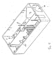
- FIGS 2 and 3 depict perspective and exploded views, respectively, of an electronic animal trap, generally designated by the reference numeral 120, which is suitable for use with the high-voltage, rearming circuitry of the present invention.
- an electronic animal trap generally designated by the reference numeral 120
- Such a trap is fully described in the copending '161 application.
- the housing 122 has a bottom wall 124, upstanding peripheral walls 126, and a roof 127 with a cover 128 carrying the switch 152 or button that toggles from an "on” or standby position to an “off” or reset position.
- the trap 120 is activated by way of the switch 152.
- the LED 154 is mounted on the cover 128 to provide visual indications of the activity and status of the trap.
- the LED 154 turns “on” or flashes to provide a visual indication to the user during activation of the trap and thereafter when the trap contains a dead mouse as will be more fully described hereinafter.
- a second LED 153, as well as others, may also be included should separate indicators of differing colors be desired.
- the cover 128 extends over an electronics area, generally designated by the reference numeral 180, with a battery lid 129 covering an area 182 which contains the power supply 184.
- the assembly may be simplified by using a single roof such as is disclosed in the '688 application.
- the high-voltage output circuitry of the present invention may be incorporated within any of the embodiments shown in the'688 application, as well as in the ⁇ 161 application, and the present application is intended to cover all such embodiments.
- the representative trap embodiment of the '161 application as shown in Figures 2-4 is more explicitly set forth herein for the purposes of increased clarity in describing the present invention.
- the bottom wall or base 124, peripheral walls 126 including back wall 134 and front wall 137, and roof 127 together define an enclosure for holding the targeted animal.
- the peripheral walls 126 include a first side 126a and a parallel second side 126b defining the elongated passageway 130.
- An entrance opening 132 at one end of the passageway 130 communicates with the exterior of the housing through an aperture in the front wall 137.
- Portions of the housing are movable between a closed position in which the captured animal is retained within the enclosure, and an opened position in which access is provided to the enclosure to remove the electrocuted animal therefrom.
- the roof 127 may pivotally rotate about hinges 135, 136 to open the trap for disposal of the carcass.
- the trap assembly further includes a floor member 140 extending along the passageway 130 intermediate the sides 126a,126b.
- the floor member 140 has a first end portion 142 juxtaposed to the front wall 137 with entrance opening 132, and an opposite second end portion 144 juxtaposed to the back wall 134.
- a pivot element 145 underlies and supports the floor member 140 intermediate its end portions for tilting movement of the floor member 140 between a first position in which the first end portion 142 is lowered and the second end portion 144 is raised, and a second position in which the first end portion 142 is raised and the second end portion 144 is lowered.
- a floor galvanized pin or carbon steel wire 147 extends through pivot 145 for permitting the floor member 140 to rotate or, more specifically, to perform a teeter-totter motion.
- a door member 160 has a bottom edge portion 165 and a top edge 164 with a hinge element 162 secured to the bottom edge portion 165 adjacent to the entrance opening 132 for pivotal movement of the door member 160 between a lowered position in which the door member 160 rests on the first end portion 142 when the floor member 140 is in its first position to provide access to the passageway 130 by a targeted animal through the entrance opening 132, and a raised position where the door member 160 blocks the entrance opening.
- a door galvanized pin or carbon steel wire 167 extends through hinge element 162 for permitting door member 160 to rotate.
- the door member 160 is biased toward its lowered position because the top edge 164 engages the roof 127 before it reaches its vertical position.
- the weight 146 mounted on the floor member 140 on the first end portion 142 thereof when the door member is in its lowered position maintains the floor member 140 in its first position, and the weight of an animal on the floor member 140 tilts the floor member 140 to its second position when the animal 150 passes from the entrance opening 132 beyond the pivot element 145 to thereby lift the door member 160 to its raised position.
- the power supply 184 which provides power to the trap can include one or more batteries, such as two AA batteries. Alternatively, the trap may be electrically connected to a wall outlet. When embodied as a battery, the power supply 184 may be conveniently located in the power supply area 182.
- the battery cover 129 is preferably snap fitted for easy entry to the area 182 to replace expired batteries.
- a bottom plate 170 is positioned near the back wall 134 and extends parallel to the bottom wall 124.
- An insulator 110 on the bottom plate 170 underlies the second end portion 144 of the floor member 140 when the floor member 140 is moved from its first position to its second position so that the target animal is only shocked when its rear paws are on the floor member 140 and its front paws are on the bottom plate 170, as will be more specifically described hereinafter.
- the high-voltage output circuit 186 is electrically connected to the power supply 184 to convert the power to electricity.
- the first electrical connection member 188 receives the electricity from the high-voltage output circuit 186 and also connects to the floor member 140 so that electricity can be provided thereto.
- the second electrical connection member 190 connects to the bottom plate 170 near the back wall 134 to provide electricity to the bottom plate 170.
- the weight of the animal 150 on the floor member 140 tilts the floor member to its second position.
- its weight lifts the door member 160 to the raised position arid blocks the animal 150 from leaving the trap.
- the bottom plate 170 and the floor member 140 are immediately adjacent one another, but kept in spaced relationship by the insulator 110.
- the advancing mouse by placing its front paws on the bottom plate 170 while its rear paws are still on the floor member 140, completes the electrical circuit, allowing an electric current to flow between the bottom plate 170 and the floor member 140 to electrocute the mouse.
- the cover may include a downwardly depending plate 80 interposed between the second end portion 144 of the floor member 140 and the bottom plate 170, forcing the target animal to squeeze under the lower edge 81 in its attempt to get to the bait. In doing so, it must then step on the bottom plate 170 and, for all intents and purposes, is precluded by its own body from pulling back before the circuitry is closed, resulting in electrocution.
- a further representative embodiment of an electronic trap suitable for use with the circuitry of the present invention is the diverter trap illustrated in Figure 5 and 6 and fully disclosed in the '688 application.
- this embodiment of the '688 application substitutes at least two fixed barriers or diverter members 70, 75 positioned between the opening 60 and the "killing chamber" 55.
- Two spaced charge plates or electrodes 50, 52 are located in the killing chamber 55 and electrically connected to the electronic circuitry in the electronics area 180'.
- the two charge plates 50, 52 in Figures 5 and 6 are configured such that contact with both charge plates simultaneously by a target animal will actuate the electric charge to effectively kill the animal.
- step 300 To commence operation of the trap, power is applied to the high-voltage output circuit 186, either from a battery 184 or an electrical outlet, and the lid is closed.
- the unit is turned on, step 300, by a user using the switch 152, thereby placing the trap into an enabled condition.
- the LED 154 flashes green once, step 302, and then turns off.
- the high-voltage output circuit 186 detects the battery status and, if the battery power is low, step 304, the LED flashes red one or more times, step 306, as a visual indicator to the user that the batteries should be replaced.
- the unit Upon conclusion of the red LED flashing procedure, and also if the battery power is found to be sufficient in step 304, the unit remains in the enabled condition in a standby mode, step 308.
- the LED may flash red on a continuing and regular basis. If the trap includes only one LED, then green flashing thereof concurrent with the red flashing will change the output color of the LED to indicate to the user that both conditions are being reported.
- the red and green colors are provided by diodes 15 of appropriate colors within the circuit 186 as shown in Figure 8 .
- the circuit 200 is automatically triggered or activated, step 310, when a known impedance is sensed across the killing plates 102, 104.
- the impedance resulting in activation of the circuit is 10k ohm to 1M ohm as a resistance level representative of a mouse or large insect.
- other resistance levels could, of course, be implemented to suit the intended target animal or insect. With a trigger resistance of less than 10k ohm, the circuit may still be activated but the output voltage is reduced.
- the circuit 186 delivers a high voltage pulse train to the killing plates 102,104. These high voltage pulses are preferably delivered as spikes of approximately 4000V occurring every 4.25ms over a 20-second killing cycle, step 312.
- the peak to peak current passing through a 1M ohm trigger resistor when the circuit is activated is about 4mA, and the load current is about 160mA.
- step 314 Upon completion of the killing cycle, current to the plates is terminated, and the battery level is checked, step 314. As before, if the battery power is low, step 314, the LED flashes red one or more times, step 316, as a visual indicator to the user that the batteries should be replaced. Upon conclusion of the red LED flashing procedure, and also if the battery power is found to be sufficient in step 314, the unit checks a stored trigger count, step 318, to determine if the circuit has been activated three times since entering the standby mode at step 308. In the standby mode, the static voltage (open circuit) level across the plates is approximately 6V DC.
- step 320 If the trigger count is equal to three, flashing of the green LED at a regular interval is initiated, step 320, and the unit does not reenter the enabled condition. Particularly, the LED flashes green once, checks to see whether 24 hours have elapsed, step 322 and, if 24 hours have not elapsed, repeats the flash and check cycle, steps 320 and 322. According to a preferred embodiment, the LED flashes green once every 5 seconds. When 24 hours have elapsed following the initiation of step 320, the unit is turned off, step 324.
- the unit checks for the continued existence of the target impedance across the plates, step 326, which indicates the continued presence of the mouse. If such resistance is still detected after about 15 seconds, the unit initiates the regular flashing and checking cycle, steps 320, 322, to visually notify the user that the trap contains an electrocuted animal. The green flashing of the LED continues until the user services the trap or for a 24 period, step 322, whichever occurs first, after which the unit is turned off.
- step 326 i.e., an open circuit (static voltage) is sensed between the killing plates upon completion of the killing cycle, the unit rearms to the enabled condition in standby mode, step 308, and thereafter awaits another mouse trigger. In this case, the LED does not illuminate, precluding the user from responding to a false-positive condition.
- the circuit in the event that the presence of the mouse is not detected following the killing cycle, the circuit will rearm itself twice in the manner just described, preferably within five seconds of completing the killing cycle.
- step 318 the flashing and rechecking cycle is entered, steps 320, 322, regardless of load impedance on the killing plates, followed by unit shutdown after 24 hours.
- the circuit may be designed to rearm a greater or fewer number of times before turning off, depending upon system and user requirements.
Landscapes
- Life Sciences & Earth Sciences (AREA)
- Pest Control & Pesticides (AREA)
- Engineering & Computer Science (AREA)
- Insects & Arthropods (AREA)
- Wood Science & Technology (AREA)
- Zoology (AREA)
- Environmental Sciences (AREA)
- Health & Medical Sciences (AREA)
- General Health & Medical Sciences (AREA)
- Toxicology (AREA)
- Catching Or Destruction (AREA)
Claims (15)
- Verfahren zum Bekämpfen von Schädlingen unter Verwenden einer elektronischen Schädlingsfalle, die einen wiederaufrüstenden Hochspannungsschaltkreis mit einem Paar beabstandeter Tötungsplatten aufweist, wobei es folgende Schritte umfasst:a) Versetzen der Falle in einen aktiven Standbymodus (308), in dem der Schaltkreis aufgrund der beabstandeten Tötungsplatten offen ist;b) automatisches Aktivieren des Schaltkreises, wenn ein Schädling das Paar beabstandeter Tötungsplatten (310) berührt, um den Schaltkreis zu schließen;c) Zuführen einer Hochspannungspulsfolge durch den Schaltkreis zu den Tötungsplatten einen einem Tötungszyklus (312) entsprechenden Zeitraum lang;d) Beenden des Stromflusses zu den Tötungsplatten bei Beendigung des Tötungszyklus (312); unde) Auslösen als Reaktion auf fortgesetzten Kontakt des Schädlings quer über die Tötungsplatten (326) eines optischen Benachrichtigungsmodus (320), der eine Notwendigkeit einer manuellen Wartung der Falle anzeigt, und Deaktivieren einer anschließenden Auslösung eines Tötungszyklus oder bei Fehlen eines fortgesetzten Kontakts des Schädlings quer über die Tötungsplatten Wiederaufrüsten der Falle (308) zu dem in Schritt a) vorgesehenen aktiven Standbymodus.
- Verfahren nach Anspruch 1, welches weiterhin nach Schritt d) den Schritt des Prüfens des Batterieladestands (314) und des Auslösens einer optischen Anzeige (316) als Reaktion auf einen niedrigen Batterieladestand umfasst.
- Verfahren nach Anspruch 1, dadurch gekennzeichnet, dass Schritt c) das Zuführen einer Pulsfolge zu den Tötungsplatten von etwa 4.000V alle 4,25 ms für etwa 20 Sekunden umfasst.
- Verfahren nach Anspruch 1, dadurch gekennzeichnet, dass der optische Benachrichtigungsmodus folgende Schritte umfasst:Auslösen eines Timers;Aktivieren von Blitzlicht einer der Falle zugeordneten LED;Vergleichen eines Werts, der von dem Timer gehalten wird, mit einem Schwellenzeitraum; undWiederholen der Schritte des Aktivierens und Vergleichens, bis der Timerwert den Schwellenzeitraum erreicht, und dann Versetzen der Falle in einen inaktiven Schlafmodus.
- Verfahren nach Anspruch 1, welches weiterhin umfasst: nach Schritt d) den Schritt des Prüfens eines gespeicherten Auslöserzählstands (318) zum Ermitteln, ob eine Summe des Tötungszyklus und einer von dem Schaltkreis durchgeführten Anzahl vorheriger Tötungszyklen einen Schwellenwert erreicht hat, und in Schritt e) auch das Auslösen des optischen Benachrichtigungsmodus (320) als Reaktion darauf, dass die Summe gleich dem Schwellenwert ist.
- Verfahren nach Anspruch 5, dadurch gekennzeichnet, dass der Schwellenwert drei ist.
- Verfahren nach Anspruch 4, dadurch gekennzeichnet, dass der Schwellenzeitraum 24 Stunden ist.
- Elektronische Schädlingsfalle, welche umfasst:einen Fallenkörper mit einer Energiequelle (184) und einem Schaltmechanismus (152) zum Versetzen der Falle in einen aktiven Standbymodus;ein Paar beabstandeter Tötungsplatten (102, 104), die in dem Fallenkörper positioniert sind; undeinen mit dem Paar beabstandeter Tötungsplatten (102,104) gekoppelten automatisch wiederaufrüstenden Hochspannungsschaltkreis (186), wobei die Falle im aktiven Standbymodus als Reaktion auf einen positiven Lasteingang über dem Paar Tötungsplatten automatisch aktiviert, so dass die Energiequelle einen Zeitraum lang, der einem Tötungszyklus entspricht, eine Hochspannungspulsfolge zu den Tötungsplatten liefert, wonach Stromfluss zu den Tötungsplatten beendet wird;Mittel zum automatischen Wiederaufrüsten des Schaltkreises als Reaktion auf einen negativen Lasteingang von den Tötungsplatten nach dem Tötungszyklus (326, 308); undMittel zum Auslösen - als Reaktion auf den fortgesetzten Erhalt des positiven Lasteingangs über den Tötungsplatten - eines optischen Benachrichtigungsmodus, der eine Notwendigkeit manueller Wartung der Falle (326, 320) anzeigt.
- Elektronische Schädlingsfalle nach Anspruch 8, dadurch gekennzeichnet, dass der Tötungszyklus das Liefern einer Pulsfolge zu den Tötungsplatten von etwa 4.000V alle 4,25 ms für etwa 20 Sekunden (312) umfasst.
- Elektronische Schädlingsfalle nach Anspruch 8, dadurch gekennzeichnet, dass der Schaltkreis bei Beendigung des Tötungszyklus einen gespeicherten Auslöserzählstand (318) prüft, um zu ermitteln, ob eine Summe des Tötungszyklus und einer von dem Schaltkreis durchgeführten Anzahl vorheriger Tötungszyklen einen Schwellenwert erreicht hat, wobei der Schaltkreis auch einen optischen Benachrichtigungsmodus (320) als Reaktion darauf, dass die Summe gleich dem Schwellenwert ist, auslöst.
- Elektronische Schädlingsfalle nach Anspruch 10, dadurch gekennzeichnet, dass der Schwellenwert drei ist.
- Elektronische Schädlingsfalle nach Anspruch 8, dadurch gekennzeichnet, dass der Schaltkreis den Batterieladestand (304, 314) prüft und eine optische Anzeige als Reaktion auf einen niedrigen Batterieladestand auslöst.
- Elektronische Schädlingsfalle nach Anspruch 12, dadurch gekennzeichnet, dass die optische Anzeige für niedrigen Batterieladestand eine rote LED (154) umfasst.
- Elektronische Schädlingsfalle nach Anspruch 8, dadurch gekennzeichnet, dass die optische Benachrichtigung eine Aktivierung einer grünen LED, so dass sie periodisch blinkt (320), umfasst.
- Elektronische Schädlingsfalle nach Anspruch 14, dadurch gekennzeichnet, dass der Schaltkreis weiterhin einen Timer zum Ermitteln einer Dauer des optischen Benachrichtigungsmodus umfasst.
Applications Claiming Priority (3)
| Application Number | Priority Date | Filing Date | Title |
|---|---|---|---|
| US46759503P | 2003-05-05 | 2003-05-05 | |
| US10/687,829 US6836999B2 (en) | 2003-05-05 | 2003-10-20 | CPU-controlled, rearming, high voltage output circuit for electronic animal trap |
| PCT/US2003/035914 WO2004098280A1 (en) | 2003-05-05 | 2003-11-12 | Cpu-controlled, rearming, high voltage output for electronic animal trap |
Publications (2)
| Publication Number | Publication Date |
|---|---|
| EP1619944A1 EP1619944A1 (de) | 2006-02-01 |
| EP1619944B1 true EP1619944B1 (de) | 2010-09-22 |
Family
ID=33436736
Family Applications (1)
| Application Number | Title | Priority Date | Filing Date |
|---|---|---|---|
| EP03796380A Expired - Lifetime EP1619944B1 (de) | 2003-05-05 | 2003-11-12 | Rechnergesteuerte elektronische tierfalle mit hochspannung |
Country Status (10)
| Country | Link |
|---|---|
| US (2) | US6836999B2 (de) |
| EP (1) | EP1619944B1 (de) |
| JP (1) | JP4575785B2 (de) |
| AT (1) | ATE481877T1 (de) |
| AU (1) | AU2003298628B2 (de) |
| CA (1) | CA2523632C (de) |
| DE (1) | DE60334324D1 (de) |
| MX (1) | MXPA05011940A (de) |
| RU (1) | RU2322807C2 (de) |
| WO (1) | WO2004098280A1 (de) |
Cited By (1)
| Publication number | Priority date | Publication date | Assignee | Title |
|---|---|---|---|---|
| EP4072287B1 (de) * | 2019-12-13 | 2024-12-04 | Woodstream Corporation | System und verfahren zur steuerung eines schockausgangs einer elektronischen tierfalle |
Families Citing this family (46)
| Publication number | Priority date | Publication date | Assignee | Title |
|---|---|---|---|---|
| EP1558075A2 (de) * | 2002-10-02 | 2005-08-03 | Ratco Aps | Elektroschock-tierfalle mit sender |
| US6836999B2 (en) * | 2003-05-05 | 2005-01-04 | Woodstream Corporation | CPU-controlled, rearming, high voltage output circuit for electronic animal trap |
| US7219466B2 (en) * | 2003-09-03 | 2007-05-22 | Woodstream Corporation | CPU-controlled, rearming electronic animal trap with three-killing-plate configuration |
| US20100331722A1 (en) * | 2004-08-10 | 2010-12-30 | Robert Martin Caudle | Device and method for assessing operant facial pain |
| US7191560B2 (en) * | 2005-01-12 | 2007-03-20 | David Harris | Flying insect trap |
| US20080120895A1 (en) * | 2005-01-23 | 2008-05-29 | Hamelin Ltd. | Rodent Management Apparatus |
| US20090102600A1 (en) | 2006-04-04 | 2009-04-23 | Noe Robert G | Pest Electrocution Device with Infrared Detector |
| US20080216387A1 (en) * | 2007-03-09 | 2008-09-11 | John Peters | Microencapsulated animal trap bait for electronic traps |
| US7841297B2 (en) * | 2007-05-07 | 2010-11-30 | Zigan Robert R | Anti-pest bird feeder apparatus |
| US7690147B2 (en) * | 2007-07-09 | 2010-04-06 | Woodstream Corporation | Rearming electronic animal trap with baffle, mechanical switch and multiple-killing-plate configuration |
| IL186667A0 (en) * | 2007-10-15 | 2008-02-09 | Peles Zalman | Electronic insect detouring device attachable to domestic object and method for use thereof |
| US8490323B2 (en) | 2007-12-14 | 2013-07-23 | Oms Investments, Inc. | Rodent trap having a pivoting platform |
| USD589583S1 (en) | 2007-12-14 | 2009-03-31 | Smg Brands, Inc. | Rodent trap |
| US7814702B2 (en) * | 2007-12-14 | 2010-10-19 | Smg Brands, Inc. | Rodent trap having a pivoting platform |
| US7886479B2 (en) * | 2007-12-14 | 2011-02-15 | Smg Brands, Inc. | Rodent trap having compressive trapping members |
| US20090151221A1 (en) * | 2007-12-14 | 2009-06-18 | Daley James D | Signaling rodent trap system |
| US7921593B2 (en) * | 2007-12-14 | 2011-04-12 | Smg Brands, Inc. | Rodent trap having a snare |
| US20090151223A1 (en) * | 2007-12-14 | 2009-06-18 | Philip Nathan | Rodent Trap Having A Pivoting Platform |
| US7757430B2 (en) * | 2008-01-03 | 2010-07-20 | Woodstream Corporation | Rearming electronic animal trap with infrared sensor and multiple-killing-plate configuration |
| MD73Z (ro) * | 2008-03-28 | 2010-04-30 | Технический университет Молдовы | Maioneză |
| USD589584S1 (en) | 2008-05-29 | 2009-03-31 | Smg Brands, Inc. | Rodent trap |
| USD577412S1 (en) | 2008-06-16 | 2008-09-23 | Smg Brands, Inc. | Rodent trap |
| US8418397B2 (en) * | 2008-06-18 | 2013-04-16 | Woodstream Corporation | Electrocuting mouse trap with automatic chamber-clearing mechanism and access control mechanism |
| US8151514B2 (en) | 2008-06-18 | 2012-04-10 | Woodstream Corporation | Electrocuting mouse trap with automatic chamber-clearing mechanism |
| WO2010074585A1 (en) * | 2008-12-23 | 2010-07-01 | Warren Roy Agnew | Eradication apparatus |
| US10070642B2 (en) * | 2011-03-02 | 2018-09-11 | Woodstream Corporation | Mousetrap with disposable, hermetically sealing cartridge and internal high-voltage killing mechanism |
| US20140085100A1 (en) | 2012-09-25 | 2014-03-27 | Woodstream Corporation | Wireless notification system and method for electronic rodent traps |
| US20140300477A1 (en) | 2012-09-25 | 2014-10-09 | Woodstream Corporation | Wireless notification systems and methods for electronic rodent traps |
| WO2016028219A1 (en) * | 2014-08-22 | 2016-02-25 | Industrial Rat Solutions Pte. Ltd | Trap and method of operating the same |
| MX389704B (es) * | 2014-12-09 | 2025-03-20 | Oms Invest Inc | Sistema de monitoreo de estacion electronica de carnada. |
| CN104780698A (zh) * | 2014-12-31 | 2015-07-15 | 苏州原点工业设计有限公司 | 一种高压直流灭鼠器电路 |
| WO2017078546A1 (en) | 2015-11-05 | 2017-05-11 | Redmayne John Michael | A trap |
| US10512258B2 (en) * | 2016-01-20 | 2019-12-24 | Joseph Baxter | Animal trap with animal entrance encouraging means |
| US9585377B1 (en) * | 2016-06-16 | 2017-03-07 | Ratio Engineering LLC | Fencing apparatus and system |
| US20180096581A1 (en) | 2016-09-30 | 2018-04-05 | Woodstream Corporation | Long range wireless notification system and method for electronic rodent traps |
| USD847295S1 (en) | 2017-01-10 | 2019-04-30 | Oms Investments, Inc. | Rodent trap |
| CA3049721A1 (en) | 2017-01-10 | 2018-07-19 | Paul R. Zeamer | Rodent trap having a pivoting platform |
| US10842145B2 (en) * | 2017-03-02 | 2020-11-24 | Woodstream Corporation | Self-arming electronic rodent trap and system and method for use thereof |
| CN107668019A (zh) * | 2017-10-24 | 2018-02-09 | 好得科技(深圳)有限公司 | 一种智能侦测安全保护电捕鼠器 |
| US11528900B2 (en) * | 2018-07-06 | 2022-12-20 | Woodstream Corporation | Wash down sensor for electronic rodent traps and method of preventing false triggering using a wash down sensor |
| GB2578312B (en) * | 2018-10-22 | 2022-02-23 | Brandenburg Uk Ltd | Rodent trap and rodent management |
| US10849320B2 (en) * | 2019-02-08 | 2020-12-01 | Jace W. Files | Pest trap with disposal container and wireless monitoring |
| WO2020192884A1 (en) * | 2019-03-25 | 2020-10-01 | Swissinno Solutions Ag | Animal trap for killing an animal, method for preventing unwanted electrical shocks by an animal trap and use of a shield in an electric animal trap |
| GB201913055D0 (en) | 2019-09-10 | 2019-10-23 | Stv Int Ltd | Pest VCapture apparatus and method |
| US20240114889A1 (en) * | 2022-10-06 | 2024-04-11 | Vm Products, Inc. | Pest control devices and methods related to assembling the same |
| IT202300023151A1 (it) * | 2023-11-03 | 2025-05-03 | Marco Paternesi | Dissuasore elettrico calpestabile per animali |
Family Cites Families (65)
| Publication number | Priority date | Publication date | Assignee | Title |
|---|---|---|---|---|
| US1660013A (en) * | 1928-02-21 | Electbomechanical bat tbap | ||
| US912203A (en) * | 1909-02-09 | Ralph A Worth | Animal-trap. | |
| GB594894A (en) | 1945-02-15 | 1947-11-21 | Electronic Traps Inc | Improvements in or relating to method and means for exterminating animals |
| US1044490A (en) * | 1911-06-05 | 1912-11-19 | John B Cessna | Animal-trap. |
| US1029551A (en) * | 1912-01-20 | 1912-06-11 | Mike Kosztotanyi | Rat-trap. |
| US1074770A (en) * | 1912-11-18 | 1913-10-07 | Claude William Beardsley | Electric rat-trap. |
| US2056882A (en) * | 1936-03-21 | 1936-10-06 | Appiani Daniel | Rodent trap |
| DE814348C (de) | 1948-10-02 | 1951-09-20 | Heinrich Tollkamp | Vorrichtung zum elektrischen Toeten von Schaedlingen |
| US3468054A (en) * | 1967-08-15 | 1969-09-23 | Irvin Levine | Electrical rodent exterminator |
| US3815278A (en) | 1971-08-05 | 1974-06-11 | A Beaton | Automatic electro-mechanical rodent trap |
| US3750158A (en) * | 1972-06-02 | 1973-07-31 | E Anastassakis | Weight sensitive security system |
| US3827176A (en) * | 1973-10-23 | 1974-08-06 | H Stirewalt | Electronic executing device for moles, gophers and the like |
| JPS5099169U (de) * | 1974-01-24 | 1975-08-18 | ||
| IT1082747B (it) * | 1977-04-12 | 1985-05-21 | Fiat Spa | Dispositivo per tenere sotto controllo la popolazione di specie selezionate di insetti |
| AU531477B2 (en) * | 1978-06-26 | 1983-08-25 | Rupert Henry Munns | Rid-mowse |
| US4205480A (en) * | 1978-08-14 | 1980-06-03 | Wilson Consolidated Enterprises, Ltd. | Rodent trap |
| GB2107164B (en) * | 1981-10-09 | 1985-08-14 | Martin Trevor Maxwell Baldwin | Vermin trap |
| US4653221A (en) * | 1982-09-24 | 1987-03-31 | Pratscher Andrew J | Animal trap |
| DE3301057C2 (de) * | 1983-01-14 | 1986-07-17 | "Kyberna", Gesellschaft für Automation, Datenverarbeitung und Messtechnik mbH, 6140 Bensheim | Vorrichtung zum Einfangen und Abtöten von kleinen Säugetieren, insbesondere Nagetieren, z.B. Mäusen |
| US4497130A (en) * | 1983-07-13 | 1985-02-05 | Fitzgerald John P | Rodent trap |
| US4566218A (en) * | 1984-12-05 | 1986-01-28 | Ikari Corporation | Apparatus for automatically trapping and processing rats or the like |
| US4709502A (en) * | 1985-09-13 | 1987-12-01 | Albert Bierman | Electric roach trap |
| JPS62116683U (de) * | 1986-01-16 | 1987-07-24 | ||
| EP0258318A4 (de) * | 1986-02-20 | 1988-06-16 | Lawrence Victor Mond Stone | Insekten- oder ungezieferfalle. |
| US4741121A (en) * | 1986-03-13 | 1988-05-03 | Andrew J. Pratscher | Gas chamber animal trap |
| US4780985A (en) * | 1987-01-12 | 1988-11-01 | Coots Claude G | Electric mouse exterminator |
| GB8704375D0 (en) * | 1987-02-25 | 1987-04-01 | Rentokil Ltd | Pest monitoring system |
| FR2689371A1 (fr) * | 1987-11-02 | 1993-10-08 | Mas Richard | Piège pour animaux. |
| US4890415A (en) * | 1988-12-19 | 1990-01-02 | Fressola Alfred A | Timing device for live animal traps |
| WO1990011685A1 (en) * | 1989-04-06 | 1990-10-18 | Knudsen Henrik Moeller | Rattrap |
| NL8901035A (nl) * | 1989-04-25 | 1990-11-16 | Ecotronics Bv | Systeem ten behoeve van registratie en/of bestrijding van knaagdieren zoals muizen en ratten. |
| US5027547A (en) * | 1990-02-07 | 1991-07-02 | Leo Livshin | Rat removal system |
| US5185953A (en) * | 1991-08-16 | 1993-02-16 | Gross Allen W | Rodent extermination device |
| US5184416A (en) * | 1991-12-02 | 1993-02-09 | Brewer Darryl C | Signal mousetrap apparatus |
| US5269091A (en) | 1992-04-29 | 1993-12-14 | Agrizap, Inc. | Portable pest electrocution device |
| US5477635A (en) * | 1993-06-29 | 1995-12-26 | Orsano; Anthony | Signaling apparatus for use with a disposable animal trap |
| NZ250372A (en) * | 1993-12-06 | 1998-10-28 | Allen Mervyn Claude | Animal trap, animal lured onto plate electrodes which are then energised to electrocute animal |
| FR2714793A1 (fr) * | 1994-01-07 | 1995-07-13 | Goutorbe Michel Stephane Eugen | Piège électrique pour limaces et escargots. |
| WO1995033372A1 (en) | 1994-06-07 | 1995-12-14 | Agrizap, Inc. | A portable pest electrocution device with resistive switch sensor |
| JP2811545B2 (ja) * | 1994-12-29 | 1998-10-15 | イカリ消毒株式会社 | ねずみ検出装置 |
| RU2087098C1 (ru) * | 1995-06-23 | 1997-08-20 | Рощупкин Евгений Яковлевич | Устройство для борьбы с грызунами - электрический дератизатор |
| FR2750294B1 (fr) * | 1996-06-27 | 1998-12-11 | Milon Jean | Dispositif pour tester l'etat d'un piege pyrotechnique a taupes |
| FR2758435B3 (fr) * | 1997-01-17 | 1999-05-14 | Jacques Richard | Appareil pour tuer les rats |
| US5953853A (en) * | 1997-03-31 | 1999-09-21 | Kim; Bok M. | Mouse and rat trap |
| JP3963486B2 (ja) * | 1997-04-29 | 2007-08-22 | ペル レンナウ | ネズミ、ハツカネズミ等を捕らえる方法及び器具 |
| ES1038557Y (es) * | 1997-09-22 | 1999-01-16 | Anton Perez Feliciano | Ratonera electrica. |
| BG62467B1 (bg) * | 1997-10-09 | 1999-12-30 | Метод и устройство за унищожаване на животни-вредители | |
| US6137415A (en) * | 1998-03-12 | 2000-10-24 | Rastar Corporation | Audio signal for spring-loaded rodent traps |
| US5918409A (en) * | 1998-06-15 | 1999-07-06 | Carnwath; James R. | Self clearing tunnel rat trap |
| FR2782601B1 (fr) * | 1998-08-31 | 2000-12-22 | Jean Emile Andre Milon | Dispositif de securite pour piege a taupe a petard |
| GB2343356A (en) * | 1998-10-02 | 2000-05-10 | Michael Charles Carter | Animal trap |
| US6195932B1 (en) * | 1999-08-17 | 2001-03-06 | Steve A. Aicher | Musical electronic insect killer |
| GB9920238D0 (en) * | 1999-08-27 | 1999-10-27 | Pearce Grahame K | Vermin trap |
| JP2001161248A (ja) * | 1999-12-07 | 2001-06-19 | Sanix Inc | ねずみ捕獲装置及びねずみ捕獲管理装置 |
| JP2001231429A (ja) * | 2000-02-18 | 2001-08-28 | Sanix Inc | ねずみ捕獲装置及びねずみ捕獲管理装置 |
| JP2002000160A (ja) * | 2000-06-19 | 2002-01-08 | Nippon Kankyo Bika Kyokai:Kk | ネズミ等の小動物捕獲装置 |
| GB0019824D0 (en) * | 2000-08-12 | 2000-09-27 | Brandenburg Uk Ltd | Improvements to rodent traps |
| US6445301B1 (en) * | 2000-09-12 | 2002-09-03 | Liphatech, Inc. | Electronic pest monitoring system and method |
| US6622422B2 (en) * | 2000-12-06 | 2003-09-23 | Woodstream Corporation | Escape-proof repeating animal trap |
| EP1465482B1 (de) * | 2002-01-14 | 2008-04-16 | Woodstream Corporation | Tierfalle |
| US6735899B1 (en) * | 2002-12-17 | 2004-05-18 | Woodstream Corporation | Animal trap |
| US6609328B2 (en) * | 2002-01-14 | 2003-08-26 | Woodstream Corporation | Electronic animal trap |
| DE60304049T2 (de) * | 2002-03-29 | 2006-10-26 | Ecolab Inc., Saint Paul | Verfahren und vorrichtung zur automatischen erzeugung von schädlingsfangberichten und zur aufzeichnung zusätzlicher fangparameterdaten |
| DE20214517U1 (de) * | 2002-09-18 | 2003-04-30 | Otto, Stephan, 33034 Brakel | Vorrichtung zum Töten von Tieren, insbesondere zum Töten von Ratten |
| US6836999B2 (en) * | 2003-05-05 | 2005-01-04 | Woodstream Corporation | CPU-controlled, rearming, high voltage output circuit for electronic animal trap |
-
2003
- 2003-10-20 US US10/687,829 patent/US6836999B2/en not_active Expired - Lifetime
- 2003-11-12 AT AT03796380T patent/ATE481877T1/de not_active IP Right Cessation
- 2003-11-12 WO PCT/US2003/035914 patent/WO2004098280A1/en not_active Ceased
- 2003-11-12 MX MXPA05011940A patent/MXPA05011940A/es active IP Right Grant
- 2003-11-12 EP EP03796380A patent/EP1619944B1/de not_active Expired - Lifetime
- 2003-11-12 AU AU2003298628A patent/AU2003298628B2/en not_active Expired
- 2003-11-12 CA CA2523632A patent/CA2523632C/en not_active Expired - Lifetime
- 2003-11-12 DE DE60334324T patent/DE60334324D1/de not_active Expired - Lifetime
- 2003-11-12 RU RU2005137692/12A patent/RU2322807C2/ru active
- 2003-11-12 JP JP2004571718A patent/JP4575785B2/ja not_active Expired - Lifetime
-
2004
- 2004-11-17 US US10/989,382 patent/US7010882B2/en not_active Expired - Lifetime
Cited By (1)
| Publication number | Priority date | Publication date | Assignee | Title |
|---|---|---|---|---|
| EP4072287B1 (de) * | 2019-12-13 | 2024-12-04 | Woodstream Corporation | System und verfahren zur steuerung eines schockausgangs einer elektronischen tierfalle |
Also Published As
| Publication number | Publication date |
|---|---|
| CA2523632A1 (en) | 2004-11-18 |
| JP4575785B2 (ja) | 2010-11-04 |
| MXPA05011940A (es) | 2006-05-31 |
| US20050144830A1 (en) | 2005-07-07 |
| CA2523632C (en) | 2011-05-17 |
| WO2004098280A1 (en) | 2004-11-18 |
| RU2322807C2 (ru) | 2008-04-27 |
| RU2005137692A (ru) | 2006-04-27 |
| JP2006524990A (ja) | 2006-11-09 |
| US6836999B2 (en) | 2005-01-04 |
| AU2003298628A1 (en) | 2004-11-26 |
| EP1619944A1 (de) | 2006-02-01 |
| DE60334324D1 (de) | 2010-11-04 |
| AU2003298628B2 (en) | 2010-11-11 |
| US7010882B2 (en) | 2006-03-14 |
| US20040231227A1 (en) | 2004-11-25 |
| ATE481877T1 (de) | 2010-10-15 |
Similar Documents
| Publication | Publication Date | Title |
|---|---|---|
| CA2523632C (en) | Cpu-controlled, rearming, high voltage output circuit for electronic animal trap | |
| US7219466B2 (en) | CPU-controlled, rearming electronic animal trap with three-killing-plate configuration | |
| US6609328B2 (en) | Electronic animal trap | |
| AU2008202869B2 (en) | Rearming electronic animal trap with baffle, mechanical switch and multiple-killing-plate configuration | |
| US8024888B2 (en) | Rearming electronic animal trap with infrared sensor and multiple-killing-plate configuration | |
| US8151514B2 (en) | Electrocuting mouse trap with automatic chamber-clearing mechanism | |
| EP1465482B1 (de) | Tierfalle | |
| CN211185601U (zh) | 一种捕鼠器 | |
| NZ539551A (en) | Rodent trap with electrodes and a floor plate that rotates relative to the cover | |
| HK1126351B (en) | Rearming electronic animal trap |
Legal Events
| Date | Code | Title | Description |
|---|---|---|---|
| PUAI | Public reference made under article 153(3) epc to a published international application that has entered the european phase |
Free format text: ORIGINAL CODE: 0009012 |
|
| 17P | Request for examination filed |
Effective date: 20051028 |
|
| AK | Designated contracting states |
Kind code of ref document: A1 Designated state(s): AT DE ES FR GB IT |
|
| DAX | Request for extension of the european patent (deleted) | ||
| RBV | Designated contracting states (corrected) |
Designated state(s): AT DE ES FR GB IT |
|
| 17Q | First examination report despatched |
Effective date: 20090218 |
|
| GRAP | Despatch of communication of intention to grant a patent |
Free format text: ORIGINAL CODE: EPIDOSNIGR1 |
|
| GRAS | Grant fee paid |
Free format text: ORIGINAL CODE: EPIDOSNIGR3 |
|
| GRAA | (expected) grant |
Free format text: ORIGINAL CODE: 0009210 |
|
| AK | Designated contracting states |
Kind code of ref document: B1 Designated state(s): AT DE ES FR GB IT |
|
| REG | Reference to a national code |
Ref country code: GB Ref legal event code: FG4D |
|
| REF | Corresponds to: |
Ref document number: 60334324 Country of ref document: DE Date of ref document: 20101104 Kind code of ref document: P |
|
| PG25 | Lapsed in a contracting state [announced via postgrant information from national office to epo] |
Ref country code: AT Free format text: LAPSE BECAUSE OF FAILURE TO SUBMIT A TRANSLATION OF THE DESCRIPTION OR TO PAY THE FEE WITHIN THE PRESCRIBED TIME-LIMIT Effective date: 20100922 |
|
| PG25 | Lapsed in a contracting state [announced via postgrant information from national office to epo] |
Ref country code: IT Free format text: LAPSE BECAUSE OF FAILURE TO SUBMIT A TRANSLATION OF THE DESCRIPTION OR TO PAY THE FEE WITHIN THE PRESCRIBED TIME-LIMIT Effective date: 20100922 |
|
| PG25 | Lapsed in a contracting state [announced via postgrant information from national office to epo] |
Ref country code: ES Free format text: LAPSE BECAUSE OF FAILURE TO SUBMIT A TRANSLATION OF THE DESCRIPTION OR TO PAY THE FEE WITHIN THE PRESCRIBED TIME-LIMIT Effective date: 20110102 |
|
| PLBE | No opposition filed within time limit |
Free format text: ORIGINAL CODE: 0009261 |
|
| STAA | Information on the status of an ep patent application or granted ep patent |
Free format text: STATUS: NO OPPOSITION FILED WITHIN TIME LIMIT |
|
| 26N | No opposition filed |
Effective date: 20110623 |
|
| REG | Reference to a national code |
Ref country code: DE Ref legal event code: R097 Ref document number: 60334324 Country of ref document: DE Effective date: 20110623 |
|
| REG | Reference to a national code |
Ref country code: FR Ref legal event code: PLFP Year of fee payment: 13 |
|
| REG | Reference to a national code |
Ref country code: FR Ref legal event code: PLFP Year of fee payment: 14 |
|
| REG | Reference to a national code |
Ref country code: FR Ref legal event code: PLFP Year of fee payment: 15 |
|
| PGFP | Annual fee paid to national office [announced via postgrant information from national office to epo] |
Ref country code: FR Payment date: 20221021 Year of fee payment: 20 |
|
| PGFP | Annual fee paid to national office [announced via postgrant information from national office to epo] |
Ref country code: GB Payment date: 20221021 Year of fee payment: 20 Ref country code: DE Payment date: 20221020 Year of fee payment: 20 |
|
| REG | Reference to a national code |
Ref country code: DE Ref legal event code: R082 Ref document number: 60334324 Country of ref document: DE Representative=s name: PRUEFER & PARTNER MBB PATENTANWAELTE RECHTSANW, DE |
|
| P01 | Opt-out of the competence of the unified patent court (upc) registered |
Effective date: 20230525 |
|
| REG | Reference to a national code |
Ref country code: DE Ref legal event code: R071 Ref document number: 60334324 Country of ref document: DE |
|
| REG | Reference to a national code |
Ref country code: GB Ref legal event code: PE20 Expiry date: 20231111 |
|
| PG25 | Lapsed in a contracting state [announced via postgrant information from national office to epo] |
Ref country code: GB Free format text: LAPSE BECAUSE OF EXPIRATION OF PROTECTION Effective date: 20231111 |
|
| PG25 | Lapsed in a contracting state [announced via postgrant information from national office to epo] |
Ref country code: GB Free format text: LAPSE BECAUSE OF EXPIRATION OF PROTECTION Effective date: 20231111 |