EP1620008B1 - Procede de simulation d'une stimulation electrique dans un systeme d'imagerie par resonance magnetique - Google Patents
Procede de simulation d'une stimulation electrique dans un systeme d'imagerie par resonance magnetique Download PDFInfo
- Publication number
- EP1620008B1 EP1620008B1 EP04728885A EP04728885A EP1620008B1 EP 1620008 B1 EP1620008 B1 EP 1620008B1 EP 04728885 A EP04728885 A EP 04728885A EP 04728885 A EP04728885 A EP 04728885A EP 1620008 B1 EP1620008 B1 EP 1620008B1
- Authority
- EP
- European Patent Office
- Prior art keywords
- stimulation
- signal
- gradient
- threshold value
- gradient coil
- Prior art date
- Legal status (The legal status is an assumption and is not a legal conclusion. Google has not performed a legal analysis and makes no representation as to the accuracy of the status listed.)
- Expired - Lifetime
Links
Images







Classifications
-
- A—HUMAN NECESSITIES
- A61—MEDICAL OR VETERINARY SCIENCE; HYGIENE
- A61B—DIAGNOSIS; SURGERY; IDENTIFICATION
- A61B5/00—Measuring for diagnostic purposes; Identification of persons
- A61B5/05—Detecting, measuring or recording for diagnosis by means of electric currents or magnetic fields; Measuring using microwaves or radio waves
- A61B5/055—Detecting, measuring or recording for diagnosis by means of electric currents or magnetic fields; Measuring using microwaves or radio waves involving electronic [EMR] or nuclear [NMR] magnetic resonance, e.g. magnetic resonance imaging
-
- A—HUMAN NECESSITIES
- A61—MEDICAL OR VETERINARY SCIENCE; HYGIENE
- A61B—DIAGNOSIS; SURGERY; IDENTIFICATION
- A61B5/00—Measuring for diagnostic purposes; Identification of persons
- A61B5/68—Arrangements of detecting, measuring or recording means, e.g. sensors, in relation to patient
- A61B5/6846—Arrangements of detecting, measuring or recording means, e.g. sensors, in relation to patient specially adapted to be brought in contact with an internal body part, i.e. invasive
- A61B5/6867—Arrangements of detecting, measuring or recording means, e.g. sensors, in relation to patient specially adapted to be brought in contact with an internal body part, i.e. invasive specially adapted to be attached or implanted in a specific body part
- A61B5/6874—Bladder
-
- A—HUMAN NECESSITIES
- A61—MEDICAL OR VETERINARY SCIENCE; HYGIENE
- A61B—DIAGNOSIS; SURGERY; IDENTIFICATION
- A61B5/00—Measuring for diagnostic purposes; Identification of persons
- A61B5/72—Signal processing specially adapted for physiological signals or for diagnostic purposes
- A61B5/7235—Details of waveform analysis
- A61B5/7239—Details of waveform analysis using differentiation including higher order derivatives
-
- A—HUMAN NECESSITIES
- A61—MEDICAL OR VETERINARY SCIENCE; HYGIENE
- A61N—ELECTROTHERAPY; MAGNETOTHERAPY; RADIATION THERAPY; ULTRASOUND THERAPY
- A61N2/00—Magnetotherapy
- A61N2/02—Magnetotherapy using magnetic fields produced by coils, including single turn loops or electromagnets
Definitions
- the present invention relates to a method for simulation of an electric stimulation of the nerve system in an MR imaging system according to the preamble portion of claim 1.
- the invention is further directed to a magnetic resonance apparatus and a computer program product for executing the simulation method according to the preamble portions of claims 10 and 13, respectively.
- Modem MRI systems utilize high gradient amplitudes and slew rates.
- rate of change (dB/dt) of the magnetic field gradients exceed a specific threshold, the patient experiences peripheral nerve stimulation (PNS).
- PNS peripheral nerve stimulation
- IEC and FDA the maximum rate of change of the magnetic field gradients used in an MRI system is regulated by the IEC and FDA.
- IEC and FDA the maximum rate of change of the magnetic field gradients used in an MRI system is regulated by the IEC and FDA.
- E electric field
- a simple model of the temporal resonse of the human nerve to this E-field yields a reasonable prediction of PNS when only simple waveforms are considered.
- Such simple approaches generally fail when any of the following conditions are met:
- an electric field E parallel to the nerve can cause an ion current through the nerve membrane (cf. J. P. Reilly, Electrical Stimulation and Electro-pathology, Cambridge University Press, 1992, pp. 213-217 and pp. 27-280 ).
- the ion current is driven by the first derivative of E.
- the ionic charge that is built up can become large enough to create an avalanche, corresponding to nerve excitation.
- the avalanche propagates along the nerve to the next node etcetera.
- the estimated required intra-patient value of E is 6 V/m (at the nerve end).
- the required field strength increases and the characteristic time involved is about 0.1 - 0.4 ms.
- Irnich points out that the situation is not equivalent to an RC circuit; instead, the relation between stimulus duration and threshold stimulus th is hyperbolic (cf. W. Irnich, F. Schmitt, Magnetostimulation in MRI, Mag. Res. Med., 33: p. 619-623, 1995 ).
- the long duration limit value of stimulus is called the rheobase rb and the characteristic time is called the chronaxie ch.
- t ⁇ h ⁇ r ⁇ b ⁇ 1 + c ⁇ h ⁇
- the Reilly threshold model and the comments of Irnich are based on experimental work with single electrically induced stimuli. Such stimuli are quite different from the typical repeated stimulus generated by the gradient waveform in the MR system. Nevertheless, the Reilly threshold model can be applied to interpret experimentally observed PNS in MR systems.
- Early work of Budinger T.F. Budinger et.al., Physiological effects of fast oscillating magnetic field gradients, JCAT 1991; 15, p. 909-914 ), Mansfield ( P. Mansfield, P.R. Harvey, Limits to Neural Stimulation in EPI, Mag. Res. Med. 1993; 29, p. 746-758 ) and Harvey ( P.R. Harvey, P. Mansfield, Avoiding peripheral nerve stimulation: gradient waveform criteria for optimum resolution in EPI, Mag. Res. Med. 1993, 32, p. 236 - 241 ) illustrate the Reilly model.
- the first filtering function f F1 (t) describes herein the excitation of the action potential on the presynaptic side, which causes chemical messenger substances to be diffused out, and is processed in a first low pass filter stage. These messenger substances are absorbed on the postsynaptic side, i.e. in nerve cells downstream, where they trigger a further action potential.
- the excitation of the action potential at the postsynaptic side is described by the filtering function f F2 (t). Since the original polarity of the excitation is no longer contained in the action potential at the postsynaptic side, only the rectified portion of the differentiated gradient signal G diff (t), which is designated Abs (G diff (t), is processed in a second low pass filter stage. Thus, the aborting of the executed measuring sequence occurs given the crossing of a threshold value in an online monitoring. This crossing of the threshold value is signaled prior to the execution of the measuring sequence in a look-ahead monitoring.
- the present invention has the aim to provide a more accurate model of the stimulation of peripheral nerves in order to optimize the threshold settings in the MR system.
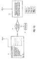
- a more accurate temporal model for the peripheral nerve response to time varying magnetic (B) and electric (E) fields can be presented in a flow diagram of the sequences of events required to determine if PNS will occur with a particular scanning method.
- the specific MR imaging method is chosen by the user and the parameters are defined.
- the explicit knowledge of the magnetic design or properties of the gradient coils GC1 and GC2 and the actual measured parameters of the specific gradient coil as shown in box 1 are implemented in decision step 2.
- the sequence parameters such as slice angulation, number of slices, gradient coil signal etc.
- step 3 the differentiated gradient signal is filtered. Thereafter the time dependent and spatially dependent E-fields for each gradient axis (G x , G y and G z ) as defined by the scanning sequence and the gradient coil properties over a single cycle TR (either in vacuum or in a cylindrical body model) are calculated in step 4.
- step 5 a 3D mask based upon a preliminary or scout scan can be obtained, in order to determine exactly where and how the patient is positioned inside the imaging volume. With such a spatial masking of the E-field space the orientation and position of the body of the patient within the gradient coil can be identified and the number of calculations can be reduced.
- step 6 the vector sum of the E-field components from each gradient coil axis over a single cycle TR is calculated, which results in a time dependent description of the overall or net E-field at various spatial locations within the gradient coil.
- step 7 the result of the vector sum is extrapolated over N times the repetition time TR and the number M of slices.
- the encoding steps and the slice angulations are included.
- additional information can be included, that relates to patient size and weight (which can be derived from the RF power calibration) in order to fine tune the threshold settings of the stimulation model on a patient by patient basis.
- the prediction or stimulation probability is evaluated for each E x (t), E y (t) and E z (t) independently.
- the nerve response is calculated as a function of space and time to yield three spatio-temporal PNS stimulation probability trajectories.
- the time points are determined where the probability of PNS exceeds the threshold at any point in the volume, for any of the E-field components. If in decision step 11 stimulation is not predicted then the scan can be executed - step 12, otherwise the sequence parameters will be modified in step 13 and the modified parameters are implemented in step 3 for another iteration.
- the modifications concerns the slew rate of the whole scan, the swap of the gradient polarity, skipping acquisitions and putting gradients to zero at critical points, etc. Since the exact point in time, of nerve stimulation, can be identified in advance, the option exists to modify the sequence in its entirety, or just around the time point of stimulation, so as to prevent the occurrence of nerve stimulation.
- the proposed novel model of PNS extends the concept of convolution of the induced current, or E-field, waveform and the nerve response.
- the following properties of the nerve have been observed and documented:
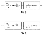
- a filter 20 which weights differently stimuli of opposite polarity as is shown in figure 2.
- the partially rectifying filter 20 also accounts for the nerve recovery time mechanism which is also resulting from non-immediate reversal of ionic concentration. Even partial, but incomplete, excitation can change the sensitivity of the nerve to the stimuli that will follow.
- the filter 20 accounts for that mechanism.
- the output, following the filter, represents some measure of the potential for the nerve to be stimulated. When the input is the E-field, then the output represents the fraction of that E-field that can be compared with the required threshold for stimulation. When the ratio is equal to 1, then stimulation occurs.
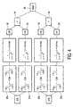
- the second filter 21 as shown in Fig. 3 operates over a longer time scale and considers only the stimuli of a single polarity.
- the output of this filter 21 behaves like a DC addition to the stimulus potential. This depends upon the longer time scale duration of the stimulus waveform. There is also an element of bias towards the initial polarity of the stimulus.
- the output represents a fraction of this E-field that must be added to the output of the first filter 20, thereby making the possibility to reach the stimulation threshold more likely.
- the outputs from the two filters 20 and 21 are therefore summed.
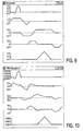
- Figure 4 illustrates the model in its entirety.
- a calibrated threshold such that an output below 1.0 indicates no stimulation and an output above 1.0 indicates stimulation.
- the differentiated waveform g(t) of the gradient coil is split in two parts.
- the negative part of the waveform g(t) is scaled with a factor 0.8.
- the lower filter stage 21a only a single polarity is considered.
- the new model has following important properties:
- Figure 5 shows validation of the model according to the present invention against published data by F. Hebrank and M. Gebhardt in ISMRM 2000, p. 2007.
- the first plot shows the performance comparing stimulation threshold dB/dt in T/sec versus gradient rise time C in ⁇ sec.
- the dashed line 28 is the output from the novel model as presented here.
- the solid line 29 is the measured Hebrank data.
- the second graph in Fig. 6 shows the results of the stimulation threshold dB/dt in T/sec as a function of the stimulation length D in msec.
- the agreement of the calculated data (dashed line 30) with the measured data from Hebrank (solid line 31) is within 10%.
- the here presented novel model is at least as accurate as the Hebrank model. However, the trend behavior is better with the novel model.
- Figure 7 shows the published Hebrank data and the accuracy of the SAFE model for comparison with Figure 6.
- the solid dots 32 present the data of a clinical study and the solid line 33 presents the calculated graph according to the SAFE model.
- the stimulation threshold dB/dt and at the abscissa the number of trapezoidal pulses P.
- Fig. 8 shows a print-out of the user screen of the console of an MRI apparatus in which the above mentioned novel model have been tested.
- Fig. 9 shows the gradient waveform plot and Fig. 10 the PNS prediction plot as calculated.
- the software developed for the novel model performs a real-time MR method optimisation/design for various sequences and hardware parameters. It utilizes the above mentioned convolution method and the novel model of the nerve to predict if peripheral nerve stimulation can occur using the sequence shown under the parameter limitations given. At the moment this prediction is displayed, per axis, in the form of the nerve response to the gradient stimuli. Values below 1.0 are below the threshold and values above 1.0 represent stimulation.
- the PNS prediction algorithm is "trained" on the Hebrank data and does take into account the longer term effects relating to the number of gradient cycles.
- the effective length of the gradient coil is in this case 0.45 m as for a typical whole body gradient coil.
- a simple FFE sequence is shown with gradient amplitude and flew rate limited to 22 mT/m and 105 T/m/s. All three axes are sub-threshold for this single repetition time TR although continuing the prediction to later TR's may show that stimulation will occur. This is implied in the EPI sequence below.
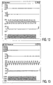
- Fig. 11 the screen print-out is showing the sequence parameters for identical sequence parameters (FOV etc.) as in to the previous case above (Fig. 8) except a 32 echo EPI readout is used.
- the PNS threshold is predicted to be exceeded for the readout (measurement) axis.
- the software would predict a stimulation. This is consistent with the knowledge that FFE is less likely to produce stimulation than EPI.
- Fig. 12 the gradient waveform plot is depicted and in Fig. 13 the PNS prediction plot.
- Fig. 14 screen print-out
- Fig. 15 gradient waveform plot
- Fig. 16 PNS prediction plot
- the supra-threshold situation B to FFE and higher gradient performance is investigated.
- a gradient performance of 40 mT/m and slew rate 200 T/m/s is assumed with a typical whole body gradient coil.
- PNS is predicted due to both the preparation axis and the measurement axis.
- FIG. 17 A practical embodiment of an MR device for executing the above mentioned method for simulation of PNS is shown in Fig. 17, which includes a first magnet system 42 for generating a steady magnetic field, and also means for generating additional magnetic fields having a gradient in the X, Y, Z directions, which means are known as gradient coils 43.
- the Z direction of the co-ordinate system shown corresponds to the direction of the steady magnetic field in the magnet system 42 by convention, which only should be linear.
- the measuring co-ordinate system x, y, z to be used can be chosen independently of the X, Y, Z system shown in Fig. 17.
- the gradient coils 43 are fed by a power supply unit 44.
- An RF transmitter coil 45 serves to generate RF magnetic fields and is connected to an RF transmitter and modulator 46.
- a receiver coil is used to receive the magnetic resonance signal generated by the RF field in the object 47 to be examined, for example a human or animal body.
- This coil 45 represents an array of multiple receiver antennae.
- the magnet system 42 encloses an examination space which is large enough to accommodate a part of the body 47 to be examined.
- the RF coil 45 is arranged around or on the part of the body 47 to be examined in this examination space.
- the RF transmitter coil 45 is connected to a signal amplifier and demodulation unit 50 via a transmission/reception circuit 49.
- the control unit 51 controls the RF transmitter and modulator 46. and the power supply unit 44 so as to generate special pulse sequences which contain RF pulses and gradients.
- the control unit 51 also controls detection of the MR signal(s), whose phase and amplitude obtained from the demodulation unit 50 are applied to a processing unit 52.
- the control unit 51 and the respective receiver coils 43 and 45 are equipped with control means to enable switching between their detection pathways on a sub-repetition time basis (i.e. typically less than 10 ms). These means comprise inter alia a current/voltage stabilisation unit to ensure reliable phase behaviour of the antennae, and one or more switches and analogue-to-digital converters in the signal path between coil and processing unit 52.
- the processing unit 52 processes the presented signal values so as to form an image by transformation. This image can be visualized, for example by means of a monitor 53.
Landscapes
- Health & Medical Sciences (AREA)
- Life Sciences & Earth Sciences (AREA)
- Physics & Mathematics (AREA)
- Molecular Biology (AREA)
- Animal Behavior & Ethology (AREA)
- Pathology (AREA)
- Engineering & Computer Science (AREA)
- Biomedical Technology (AREA)
- Heart & Thoracic Surgery (AREA)
- Medical Informatics (AREA)
- Nuclear Medicine, Radiotherapy & Molecular Imaging (AREA)
- Surgery (AREA)
- Biophysics (AREA)
- General Health & Medical Sciences (AREA)
- Public Health (AREA)
- Veterinary Medicine (AREA)
- High Energy & Nuclear Physics (AREA)
- Urology & Nephrology (AREA)
- Radiology & Medical Imaging (AREA)
- Magnetic Resonance Imaging Apparatus (AREA)
- Electrotherapy Devices (AREA)
- Magnetic Treatment Devices (AREA)
Claims (15)
- Procédé de simulation d'une stimulation électrique du système nerveux d'un sujet à examiner générée par la vitesse de variation de champs de gradient générés par une ou plusieurs bobines de gradient d'un système d'imagerie par résonance magnétique, dans lequel un signal de gradient est filtré avec une fonction de filtrage, un signal de stimulation est dérivé dudit signal de gradient filtré, et ledit signal de stimulation est comparé avec une valeur de seuil de stimulation prédéterminée pour générer un signal indicateur si ladite valeur de seuil est dépassée, caractérisé par- le calcul des champs électriques dépendant du temps et de l'espace, définis par la séquence de balayage et les propriétés des bobines de gradient,- la combinaison vectorielle desdites composantes de champ électrique calculées de chaque axe de bobine de gradient donnant un diagramme temporel du champ électrique total à différents endroits spatiaux dans la bobine de gradient,- le calcul de la probabilité de stimulation à chaque endroit dudit diagramme temporel et dudit signal de stimulation, et- la comparaison de ladite probabilité de stimulation avec la valeur de seuil de stimulation à chaque endroit dans la bobine de gradient.
- Procédé suivant la revendication 1, dans lequel le signal de gradient différentié est filtré dans un premier étage avec un premier filtre bipolaire et est et est filtré en parallèle dans un premier filtre unipolaire, les signaux de sortie des deux premiers filtres étant pondérés et les signaux de sortie pondérés étant additionnés.
- Procédé suivant la revendication 2, dans lequel le signal de gradient différentié inverse est filtré en parallèle dans un second étage de filtrage avec un second filtre bipolaire et un second filtre unipolaire parallèle, les signaux de sortie des deux seconds filtres sont pondérés et les signaux de sortie pondérés sont ajoutés à un second signal de stimulation, qui est comparé avec le premier signal de stimulation et le maximum des deux signaux de stimulation est utilisé comme signal de sortie pour la comparaison avec ladite valeur de seuil.
- Procédé suivant l'une quelconque des revendications 1 à 3, dans lequel la connaissance de la conception magnétique des bobines de gradient est incorporée dans le calcul.
- Procédé suivant l'une quelconque des revendications 1 à 4, dans lequel la connaissance dérivée de l'effet de la charge de patient est pondérée dans la probabilité de stimulation pour la taille et/ou la position du patient.
- Procédé suivant l'une quelconque des revendications 1 à 5, dans lequel la séquence d'impulsions RM du procédé d'imagerie RM présélectionné est affinée par rétroaction du signal de probabilité de stimulation prédite.
- Procédé suivant l'une quelconque des revendications 1 à 6, dans lequel l'espace du champ électrique est spatialement masqué par un masque dérivé d'une image RM de vision préliminaire du corps du patient dans la bobine de gradient.
- Procédé suivant l'une quelconque des revendications 1 à 7, dans lequel les composantes dépendant du temps du champ électrique dans les directions x, y et z sont extrapolées sur de multiples périodes de répétition et de multiples coupes.
- Procédé suivant la revendication 8, dans lequel les points dans le temps et les positions dans le volume de la bobine de gradient sont calculés pour chaque composante du champ électrique de manière indépendante et chaque probabilité de stimulation prédite est comparée avec la valeur de seuil de stimulation.
- Appareil d'imagerie par résonance magnétique visant à obtenir une image RM à partir d'une pluralité de signaux comprenant un aimant de champ principal et des bobines de gradient; des moyens pour simuler une stimulation électrique du système nerveux d'un sujet à examiner, laquelle stimulation est générée par la vitesse de variation des champs de gradient, des moyens pour filtrer le signal de gradient avec une fonction de filtrage : des moyens pour dériver un signal de stimulation dudit signal de gradient filtré, et des moyens pour comparer ledit signal de stimulation avec une valeur de seuil de stimulation prédéterminée pour générer un signal indicateur si ladite valeur de seuil est dépassée, caractérisé par :- des moyens pour calculer des champs électriques dépendant du temps et dépendant de l'espace, définis par la séquence de balayage et les propriétés de bobines de gradient,- des moyens pour la combinaison vectorielle desdites composantes de champs électriques calculés à partir de chaque axe de bobine de gradient, ce qui donne un diagramme temporel du champ électrique total en différents endroits spatiaux dans la bobine de gradient,- des moyens pour calculer la probabilité de stimulation à chaque endroit à partir dudit diagramme temporel et dudit signal de stimulation, et- des moyens pour comparer ladite probabilité de stimulation avec la valeur de seuil de stimulation à chaque endroit dans la bobine de gradient.
- Appareil d'imagerie par résonance magnétique suivant la revendication 10, caractérisé par un premier étage de filtrage avec un premier filtre bipolaire pour filtrer le signal de gradient différentié et un premier filtre unipolaire pour le filtrage parallèle dudit signal et des moyens de pondération dans lesquels les signaux de sortie pondérés sont additionnés.
- Appareil d'imagerie par résonance magnétique suivant la revendication 11, caractérisé par un second étage de filtrage parallèle avec un second filtre bipolaire pour filtrer le signal de gradient différentié inverse pendant approximativement une seule période de temps de répétition, avec un second filtre unipolaire parallèle pour filtrer en parallèle ledit signal pendant approximativement dix ou plus de dix périodes de temps de répétition, et des moyens de pondération dans lesquels les deux signaux de sortie sont pondérés, et des moyens d'addition dans lesquels les signaux de sortie pondérés sont ajoutés à un second signal de stimulation, et des moyens pour comparer ledit premier signal de stimulation avec ledit second signal de stimulation et des moyens pour définir le maximum des deux signaux de stimulation comme signal de sortie pour la comparaison avec ladite valeur de seuil de stimulation.
- Progiciel d'ordinateur stocké sur un support utilisable par un ordinateur pour former une image au moyen d'un procédé de résonance magnétique comprenant un procédé de simulation d'une stimulation électrique du système nerveux d'un sujet à examiner généré par la vitesse de variation de champs de gradient d'une bobine de gradient d'un système d'imagerie par résonance magnétique; comprenant un programme lisible par ordinateur pour amener l'ordinateur à commander l'exécution de :- filtrage du signal de gradient de ladite bobine de gradient avec une fonction de filtrage,- dérivation d'un signal de stimulation à partir dudit signal de gradient filtré,- comparaison dudit signal de stimulation avec une valeur de seuil de stimulation prédéterminée pour générer un signal indicateur si ladite valeur de seuil est dépassée,- calcul des champs électriques dépendant du temps et dépendant de l'espace, définis par la séquence de balayage et les propriétés de bobine de gradient,- combinaison vectorielle desdites composantes de champs électriques calculées à partir de chaque axe de bobine de gradient, donnant un diagramme temporel du champ électrique total à différents endroits spatiaux au sein de la bobine de gradient,- calcul de la probabilité de stimulation à chaque endroit à partir dudit diagramme temporel et dudit signal de stimulation, et- comparaison de ladite probabilité de stimulation avec la valeur de seuil de stimulation à chaque endroit au sein de la bobine de gradient.
- Progiciel d'ordinateur suivant la revendication 13, amenant en outre l'ordinateur à commander l'exécution de :- filtrage du signal de gradient différentié dans un premier étage avec un premier filtre bipolaire,- filtrage parallèle dudit signal de gradient différentié dans un premier filtre unipolaire, et- pondération des signaux de sortie des deux premiers filtres et addition des signaux de sortie pondérés.
- Progiciel d'ordinateur suivant la revendication 14, amenant en outre l'ordinateur à commander l'exécution de :- filtrage du signal de gradient différentié inverse dans un second étage de filtrage avec un second filtre bipolaire pendant approximativement une seule période de temps de répétition,- filtrage parallèle dudit signal inverse avec un second filtre unipolaire parallèle pendant approximativement dix ou plus de dix périodes de temps de répétition,- pondération des deux signaux de sortie,- addition des signaux de sortie pondérés à un second signal de stimulation,- comparaison dudit premier signal de stimulation avec ledit second signal de stimulation et- définition du maximum des deux signaux de stimulation comme signal de sortie pour comparaison avec ladite valeur de seuil de stimulation;- filtrage du signal de gradient différentié inverse en parallèle dans un second étage de filtrage avec un second filtre bipolaire;- filtrage dudit signal inverse dans un second étage de filtrage, les signaux de sortie des deux seconds filtres étant pondérés et les signaux de sortie pondérés étant additionnés à un second signal de stimulation, qui est comparé avec le premier signal de stimulation et le maximum des deux signaux de stimulation est utilisé comme signal de sortie pour comparaison avec ladite valeur de seuil.
Priority Applications (1)
| Application Number | Priority Date | Filing Date | Title |
|---|---|---|---|
| EP04728885A EP1620008B1 (fr) | 2003-04-24 | 2004-04-22 | Procede de simulation d'une stimulation electrique dans un systeme d'imagerie par resonance magnetique |
Applications Claiming Priority (3)
| Application Number | Priority Date | Filing Date | Title |
|---|---|---|---|
| EP03101145 | 2003-04-24 | ||
| EP04728885A EP1620008B1 (fr) | 2003-04-24 | 2004-04-22 | Procede de simulation d'une stimulation electrique dans un systeme d'imagerie par resonance magnetique |
| PCT/IB2004/050489 WO2004093680A1 (fr) | 2003-04-24 | 2004-04-22 | Procede de simulation d'une stimulation electrique dans un systeme d'imagerie par resonance magnetique |
Publications (2)
| Publication Number | Publication Date |
|---|---|
| EP1620008A1 EP1620008A1 (fr) | 2006-02-01 |
| EP1620008B1 true EP1620008B1 (fr) | 2007-09-19 |
Family
ID=33305805
Family Applications (1)
| Application Number | Title | Priority Date | Filing Date |
|---|---|---|---|
| EP04728885A Expired - Lifetime EP1620008B1 (fr) | 2003-04-24 | 2004-04-22 | Procede de simulation d'une stimulation electrique dans un systeme d'imagerie par resonance magnetique |
Country Status (6)
| Country | Link |
|---|---|
| US (1) | US7412278B2 (fr) |
| EP (1) | EP1620008B1 (fr) |
| JP (1) | JP4538450B2 (fr) |
| AT (1) | ATE373445T1 (fr) |
| DE (1) | DE602004009052T2 (fr) |
| WO (1) | WO2004093680A1 (fr) |
Families Citing this family (14)
| Publication number | Priority date | Publication date | Assignee | Title |
|---|---|---|---|---|
| US7818273B2 (en) * | 2007-09-18 | 2010-10-19 | International Business Machines Corporation | System and method for cortical simulation |
| US20110118587A1 (en) * | 2008-03-04 | 2011-05-19 | Roemer Peter B | Optimization of rf transmit and gradient magnetic field imaging using radio frequency and gradient coils |
| JP5518403B2 (ja) * | 2008-09-09 | 2014-06-11 | 株式会社東芝 | 磁気共鳴イメージング装置及び磁気共鳴イメージング方法 |
| US8030920B2 (en) * | 2009-06-03 | 2011-10-04 | General Electric Company | Method and system for modifying pulse sequences |
| CN102109586B (zh) * | 2009-12-23 | 2015-02-11 | Ge医疗系统环球技术有限公司 | 磁共振梯度脉冲波设计方法及其装置 |
| CN104345288B (zh) * | 2013-07-31 | 2018-01-16 | 上海联影医疗科技有限公司 | 磁共振梯度场刺激水平计算方法、装置及控制方法、系统 |
| DE102014202183A1 (de) * | 2014-02-06 | 2015-08-06 | Siemens Aktiengesellschaft | Verfahren zum Anpassen von bei der Ansteuerung eines Magnetresonanzsystems verwendeten Ansteuerparametern zum Erzeugen einer Pulssequenz und entsprechende Vorrichtung |
| CN107635496B (zh) * | 2015-05-12 | 2021-08-17 | 圣犹达医疗用品电生理部门有限公司 | 用于交流心脏不可逆电穿孔的非对称平衡波形 |
| DE102016202062A1 (de) | 2016-02-11 | 2017-08-17 | Siemens Healthcare Gmbh | Überprüfung von Vorgaben für Magnetresonanzuntersuchungen, insbesondere von Implantat-Trägern |
| DE102016203254B4 (de) * | 2016-02-29 | 2019-06-27 | Siemens Healthcare Gmbh | Berechnung von Stimulationswerten in der MRT |
| DE102016217223A1 (de) * | 2016-09-09 | 2018-03-15 | Siemens Healthcare Gmbh | Überprüfung einer zeitlichen Änderung eines Magnetfeldes in einer Magnetresonanzvorrichtung |
| EP3770623A1 (fr) * | 2019-07-24 | 2021-01-27 | Siemens Healthcare GmbH | Procédé de commande des effets de stimulation d'un patient en imagerie par résonance magnétique, programme informatique correspondant, support d'enregistrement lisible sur ordinateur et dispositif d'imagerie par résonance magnétique |
| EP3906850A1 (fr) * | 2020-05-08 | 2021-11-10 | Koninklijke Philips N.V. | Appareil de détection de la stimulation du nerf périphérique |
| EP3923014A1 (fr) | 2020-06-12 | 2021-12-15 | Koninklijke Philips N.V. | Préparation de patient pour l'imagerie médicale |
Family Cites Families (2)
| Publication number | Priority date | Publication date | Assignee | Title |
|---|---|---|---|---|
| US6169403B1 (en) * | 1998-04-29 | 2001-01-02 | Siemens Aktiengesellschaft | Method and MR device for simulating electrical simulations in a subject by MR stimulation |
| DE10010899C1 (de) | 2000-03-06 | 2001-09-06 | Siemens Ag | Verfahren und Vorrichtung zur Steigerung der Leistungsfähigkeit von Magnetresonanz-Tomographieanlagen |
-
2004
- 2004-04-22 AT AT04728885T patent/ATE373445T1/de not_active IP Right Cessation
- 2004-04-22 JP JP2006506880A patent/JP4538450B2/ja not_active Expired - Fee Related
- 2004-04-22 EP EP04728885A patent/EP1620008B1/fr not_active Expired - Lifetime
- 2004-04-22 WO PCT/IB2004/050489 patent/WO2004093680A1/fr not_active Ceased
- 2004-04-22 US US10/554,339 patent/US7412278B2/en not_active Expired - Fee Related
- 2004-04-22 DE DE602004009052T patent/DE602004009052T2/de not_active Expired - Lifetime
Also Published As
| Publication number | Publication date |
|---|---|
| DE602004009052T2 (de) | 2008-06-12 |
| US7412278B2 (en) | 2008-08-12 |
| EP1620008A1 (fr) | 2006-02-01 |
| DE602004009052D1 (de) | 2007-10-31 |
| WO2004093680A1 (fr) | 2004-11-04 |
| ATE373445T1 (de) | 2007-10-15 |
| JP4538450B2 (ja) | 2010-09-08 |
| US20070010737A1 (en) | 2007-01-11 |
| JP2006524089A (ja) | 2006-10-26 |
Similar Documents
| Publication | Publication Date | Title |
|---|---|---|
| EP1620008B1 (fr) | Procede de simulation d'une stimulation electrique dans un systeme d'imagerie par resonance magnetique | |
| US6198282B1 (en) | Optimized MRI gradient system for providing minimum-duration gradient pulses | |
| Glover | Interaction of MRI field gradients with the human body | |
| US10012714B2 (en) | Method and device for optimizing magnetic resonance system operating sequences with respect to physiological limiting values | |
| US8547097B2 (en) | SAR calculation for multichannel MR transmission systems | |
| US8115484B2 (en) | Method and device to generate a measurement sequence for operating a magnetic resonance system that is adapted to the time raster of the system | |
| US10534048B2 (en) | Magnetic resonance imaging apparatus and SAR prediction method | |
| US20030036693A1 (en) | Method to obtain the cardiac gating signal using a cardiac displacement sensor | |
| US7187172B2 (en) | Method for controlling an RF transmission device, and MR apparatus and RF device for implementing the method | |
| Karpowicz et al. | Health risk assessment of occupational exposure to a magnetic field from magnetic resonance imaging devices | |
| US20070145975A1 (en) | Method and magnetic resonance system for adjustment of the field strength of rf pulses | |
| WO2009111027A2 (fr) | Optimisation de transmission rf et imagerie à gradient de champ magnétique utilisant des bobines radio fréquence et de gradient | |
| US6298258B1 (en) | Method and apparatus for spatially resolved measurement of the electrical activity of nerve cells using magnetic resonance | |
| US20080309333A1 (en) | Motion-Dependent Data Acquisition in Magnetic Resonance Imaging and Spectroscopy | |
| US7047062B2 (en) | Magnetic resonance imaging with nested gradient pulses | |
| US9606208B2 (en) | Magnetic resonance system, and device and method for control thereof | |
| US6759848B2 (en) | Magnetic resonance method and apparatus for spatially resolved presentation of change in the functional activities of a brain | |
| US10663538B2 (en) | Monitoring of a temporal change in a magnetic field in a magnetic resonance device | |
| US10175323B2 (en) | Adapting activation parameters used to generate a pulse sequence when activating a magnetic resonance system | |
| Bailey et al. | Thresholds for 60 Hz magnetic field stimulation of peripheral nerves in human subjects | |
| JP2001276018A (ja) | 磁気共鳴トモグラフィ装置の出力能力を最適に利用するための方法および装置 | |
| US10788552B2 (en) | Method and control unit for operating a gradient coil device of an MRI system or another periodically stressed device | |
| JP6867857B2 (ja) | 磁気共鳴撮像装置 | |
| Lee et al. | Derivation and properties of the convolution model for MRI gradient-induced cardiac stimulation | |
| Turk et al. | Experimental and theoretical analysis of the induced voltage along implant leads due to gradient fields |
Legal Events
| Date | Code | Title | Description |
|---|---|---|---|
| PUAI | Public reference made under article 153(3) epc to a published international application that has entered the european phase |
Free format text: ORIGINAL CODE: 0009012 |
|
| 17P | Request for examination filed |
Effective date: 20051124 |
|
| AK | Designated contracting states |
Kind code of ref document: A1 Designated state(s): AT BE BG CH CY CZ DE DK EE ES FI FR GB GR HU IE IT LI LU MC NL PL PT RO SE SI SK TR |
|
| DAX | Request for extension of the european patent (deleted) | ||
| GRAP | Despatch of communication of intention to grant a patent |
Free format text: ORIGINAL CODE: EPIDOSNIGR1 |
|
| GRAS | Grant fee paid |
Free format text: ORIGINAL CODE: EPIDOSNIGR3 |
|
| GRAA | (expected) grant |
Free format text: ORIGINAL CODE: 0009210 |
|
| AK | Designated contracting states |
Kind code of ref document: B1 Designated state(s): AT BE BG CH CY CZ DE DK EE ES FI FR GB GR HU IE IT LI LU MC NL PL PT RO SE SI SK TR |
|
| REG | Reference to a national code |
Ref country code: GB Ref legal event code: FG4D |
|
| REG | Reference to a national code |
Ref country code: CH Ref legal event code: EP |
|
| REF | Corresponds to: |
Ref document number: 602004009052 Country of ref document: DE Date of ref document: 20071031 Kind code of ref document: P |
|
| REG | Reference to a national code |
Ref country code: IE Ref legal event code: FG4D |
|
| REG | Reference to a national code |
Ref country code: GB Ref legal event code: 746 Effective date: 20071212 |
|
| PG25 | Lapsed in a contracting state [announced via postgrant information from national office to epo] |
Ref country code: FI Free format text: LAPSE BECAUSE OF FAILURE TO SUBMIT A TRANSLATION OF THE DESCRIPTION OR TO PAY THE FEE WITHIN THE PRESCRIBED TIME-LIMIT Effective date: 20070919 |
|
| PG25 | Lapsed in a contracting state [announced via postgrant information from national office to epo] |
Ref country code: PL Free format text: LAPSE BECAUSE OF FAILURE TO SUBMIT A TRANSLATION OF THE DESCRIPTION OR TO PAY THE FEE WITHIN THE PRESCRIBED TIME-LIMIT Effective date: 20070919 Ref country code: CH Free format text: LAPSE BECAUSE OF FAILURE TO SUBMIT A TRANSLATION OF THE DESCRIPTION OR TO PAY THE FEE WITHIN THE PRESCRIBED TIME-LIMIT Effective date: 20070919 Ref country code: AT Free format text: LAPSE BECAUSE OF FAILURE TO SUBMIT A TRANSLATION OF THE DESCRIPTION OR TO PAY THE FEE WITHIN THE PRESCRIBED TIME-LIMIT Effective date: 20070919 Ref country code: LI Free format text: LAPSE BECAUSE OF FAILURE TO SUBMIT A TRANSLATION OF THE DESCRIPTION OR TO PAY THE FEE WITHIN THE PRESCRIBED TIME-LIMIT Effective date: 20070919 |
|
| NLV1 | Nl: lapsed or annulled due to failure to fulfill the requirements of art. 29p and 29m of the patents act | ||
| PG25 | Lapsed in a contracting state [announced via postgrant information from national office to epo] |
Ref country code: BE Free format text: LAPSE BECAUSE OF FAILURE TO SUBMIT A TRANSLATION OF THE DESCRIPTION OR TO PAY THE FEE WITHIN THE PRESCRIBED TIME-LIMIT Effective date: 20070919 |
|
| REG | Reference to a national code |
Ref country code: CH Ref legal event code: PL |
|
| PG25 | Lapsed in a contracting state [announced via postgrant information from national office to epo] |
Ref country code: ES Free format text: LAPSE BECAUSE OF FAILURE TO SUBMIT A TRANSLATION OF THE DESCRIPTION OR TO PAY THE FEE WITHIN THE PRESCRIBED TIME-LIMIT Effective date: 20071230 Ref country code: NL Free format text: LAPSE BECAUSE OF FAILURE TO SUBMIT A TRANSLATION OF THE DESCRIPTION OR TO PAY THE FEE WITHIN THE PRESCRIBED TIME-LIMIT Effective date: 20070919 Ref country code: GR Free format text: LAPSE BECAUSE OF FAILURE TO SUBMIT A TRANSLATION OF THE DESCRIPTION OR TO PAY THE FEE WITHIN THE PRESCRIBED TIME-LIMIT Effective date: 20071220 |
|
| EN | Fr: translation not filed | ||
| PG25 | Lapsed in a contracting state [announced via postgrant information from national office to epo] |
Ref country code: SK Free format text: LAPSE BECAUSE OF FAILURE TO SUBMIT A TRANSLATION OF THE DESCRIPTION OR TO PAY THE FEE WITHIN THE PRESCRIBED TIME-LIMIT Effective date: 20070919 Ref country code: PT Free format text: LAPSE BECAUSE OF FAILURE TO SUBMIT A TRANSLATION OF THE DESCRIPTION OR TO PAY THE FEE WITHIN THE PRESCRIBED TIME-LIMIT Effective date: 20080219 Ref country code: CZ Free format text: LAPSE BECAUSE OF FAILURE TO SUBMIT A TRANSLATION OF THE DESCRIPTION OR TO PAY THE FEE WITHIN THE PRESCRIBED TIME-LIMIT Effective date: 20070919 |
|
| PG25 | Lapsed in a contracting state [announced via postgrant information from national office to epo] |
Ref country code: SE Free format text: LAPSE BECAUSE OF FAILURE TO SUBMIT A TRANSLATION OF THE DESCRIPTION OR TO PAY THE FEE WITHIN THE PRESCRIBED TIME-LIMIT Effective date: 20071219 Ref country code: RO Free format text: LAPSE BECAUSE OF FAILURE TO SUBMIT A TRANSLATION OF THE DESCRIPTION OR TO PAY THE FEE WITHIN THE PRESCRIBED TIME-LIMIT Effective date: 20070919 |
|
| PLBE | No opposition filed within time limit |
Free format text: ORIGINAL CODE: 0009261 |
|
| STAA | Information on the status of an ep patent application or granted ep patent |
Free format text: STATUS: NO OPPOSITION FILED WITHIN TIME LIMIT |
|
| PG25 | Lapsed in a contracting state [announced via postgrant information from national office to epo] |
Ref country code: DK Free format text: LAPSE BECAUSE OF FAILURE TO SUBMIT A TRANSLATION OF THE DESCRIPTION OR TO PAY THE FEE WITHIN THE PRESCRIBED TIME-LIMIT Effective date: 20070919 |
|
| 26N | No opposition filed |
Effective date: 20080620 |
|
| PG25 | Lapsed in a contracting state [announced via postgrant information from national office to epo] |
Ref country code: FR Free format text: LAPSE BECAUSE OF FAILURE TO SUBMIT A TRANSLATION OF THE DESCRIPTION OR TO PAY THE FEE WITHIN THE PRESCRIBED TIME-LIMIT Effective date: 20080523 |
|
| PG25 | Lapsed in a contracting state [announced via postgrant information from national office to epo] |
Ref country code: MC Free format text: LAPSE BECAUSE OF NON-PAYMENT OF DUE FEES Effective date: 20080430 |
|
| PG25 | Lapsed in a contracting state [announced via postgrant information from national office to epo] |
Ref country code: EE Free format text: LAPSE BECAUSE OF FAILURE TO SUBMIT A TRANSLATION OF THE DESCRIPTION OR TO PAY THE FEE WITHIN THE PRESCRIBED TIME-LIMIT Effective date: 20070919 |
|
| PG25 | Lapsed in a contracting state [announced via postgrant information from national office to epo] |
Ref country code: IE Free format text: LAPSE BECAUSE OF NON-PAYMENT OF DUE FEES Effective date: 20080422 |
|
| PG25 | Lapsed in a contracting state [announced via postgrant information from national office to epo] |
Ref country code: SI Free format text: LAPSE BECAUSE OF FAILURE TO SUBMIT A TRANSLATION OF THE DESCRIPTION OR TO PAY THE FEE WITHIN THE PRESCRIBED TIME-LIMIT Effective date: 20070919 |
|
| PG25 | Lapsed in a contracting state [announced via postgrant information from national office to epo] |
Ref country code: CY Free format text: LAPSE BECAUSE OF FAILURE TO SUBMIT A TRANSLATION OF THE DESCRIPTION OR TO PAY THE FEE WITHIN THE PRESCRIBED TIME-LIMIT Effective date: 20070919 |
|
| PG25 | Lapsed in a contracting state [announced via postgrant information from national office to epo] |
Ref country code: BG Free format text: LAPSE BECAUSE OF FAILURE TO SUBMIT A TRANSLATION OF THE DESCRIPTION OR TO PAY THE FEE WITHIN THE PRESCRIBED TIME-LIMIT Effective date: 20071219 |
|
| PG25 | Lapsed in a contracting state [announced via postgrant information from national office to epo] |
Ref country code: HU Free format text: LAPSE BECAUSE OF FAILURE TO SUBMIT A TRANSLATION OF THE DESCRIPTION OR TO PAY THE FEE WITHIN THE PRESCRIBED TIME-LIMIT Effective date: 20080320 Ref country code: LU Free format text: LAPSE BECAUSE OF NON-PAYMENT OF DUE FEES Effective date: 20080422 |
|
| PG25 | Lapsed in a contracting state [announced via postgrant information from national office to epo] |
Ref country code: TR Free format text: LAPSE BECAUSE OF FAILURE TO SUBMIT A TRANSLATION OF THE DESCRIPTION OR TO PAY THE FEE WITHIN THE PRESCRIBED TIME-LIMIT Effective date: 20070919 |
|
| PG25 | Lapsed in a contracting state [announced via postgrant information from national office to epo] |
Ref country code: IT Free format text: LAPSE BECAUSE OF NON-PAYMENT OF DUE FEES Effective date: 20080430 |
|
| PGFP | Annual fee paid to national office [announced via postgrant information from national office to epo] |
Ref country code: GB Payment date: 20120430 Year of fee payment: 9 |
|
| PGFP | Annual fee paid to national office [announced via postgrant information from national office to epo] |
Ref country code: DE Payment date: 20120702 Year of fee payment: 9 |
|
| GBPC | Gb: european patent ceased through non-payment of renewal fee |
Effective date: 20130422 |
|
| PG25 | Lapsed in a contracting state [announced via postgrant information from national office to epo] |
Ref country code: DE Free format text: LAPSE BECAUSE OF NON-PAYMENT OF DUE FEES Effective date: 20131101 Ref country code: GB Free format text: LAPSE BECAUSE OF NON-PAYMENT OF DUE FEES Effective date: 20130422 |
|
| REG | Reference to a national code |
Ref country code: DE Ref legal event code: R119 Ref document number: 602004009052 Country of ref document: DE Effective date: 20131101 |