EP1620137B1 - Duftspender - Google Patents
Duftspender Download PDFInfo
- Publication number
- EP1620137B1 EP1620137B1 EP04729669A EP04729669A EP1620137B1 EP 1620137 B1 EP1620137 B1 EP 1620137B1 EP 04729669 A EP04729669 A EP 04729669A EP 04729669 A EP04729669 A EP 04729669A EP 1620137 B1 EP1620137 B1 EP 1620137B1
- Authority
- EP
- European Patent Office
- Prior art keywords
- fan
- flow controller
- arm
- fragrance
- passage
- Prior art date
- Legal status (The legal status is an assumption and is not a legal conclusion. Google has not performed a legal analysis and makes no representation as to the accuracy of the status listed.)
- Expired - Lifetime
Links
Images


Classifications
-
- A—HUMAN NECESSITIES
- A61—MEDICAL OR VETERINARY SCIENCE; HYGIENE
- A61L—METHODS OR APPARATUS FOR STERILISING MATERIALS OR OBJECTS IN GENERAL; DISINFECTION, STERILISATION OR DEODORISATION OF AIR; CHEMICAL ASPECTS OF BANDAGES, DRESSINGS, ABSORBENT PADS OR SURGICAL ARTICLES; MATERIALS FOR BANDAGES, DRESSINGS, ABSORBENT PADS OR SURGICAL ARTICLES
- A61L9/00—Disinfection, sterilisation or deodorisation of air
- A61L9/015—Disinfection, sterilisation or deodorisation of air using gaseous or vaporous substances, e.g. ozone
-
- A—HUMAN NECESSITIES
- A61—MEDICAL OR VETERINARY SCIENCE; HYGIENE
- A61L—METHODS OR APPARATUS FOR STERILISING MATERIALS OR OBJECTS IN GENERAL; DISINFECTION, STERILISATION OR DEODORISATION OF AIR; CHEMICAL ASPECTS OF BANDAGES, DRESSINGS, ABSORBENT PADS OR SURGICAL ARTICLES; MATERIALS FOR BANDAGES, DRESSINGS, ABSORBENT PADS OR SURGICAL ARTICLES
- A61L9/00—Disinfection, sterilisation or deodorisation of air
- A61L9/015—Disinfection, sterilisation or deodorisation of air using gaseous or vaporous substances, e.g. ozone
- A61L9/04—Disinfection, sterilisation or deodorisation of air using gaseous or vaporous substances, e.g. ozone using substances evaporated in the air without heating
- A61L9/12—Apparatus, e.g. holders, therefor
- A61L9/127—Apparatus, e.g. holders, therefor comprising a wick
-
- A—HUMAN NECESSITIES
- A45—HAND OR TRAVELLING ARTICLES
- A45D—HAIRDRESSING OR SHAVING EQUIPMENT; EQUIPMENT FOR COSMETICS OR COSMETIC TREATMENTS, e.g. FOR MANICURING OR PEDICURING
- A45D34/00—Containers or accessories specially adapted for handling liquid toiletry or cosmetic substances, e.g. perfumes
- A45D34/02—Scent flasks, e.g. with evaporator
-
- A—HUMAN NECESSITIES
- A61—MEDICAL OR VETERINARY SCIENCE; HYGIENE
- A61L—METHODS OR APPARATUS FOR STERILISING MATERIALS OR OBJECTS IN GENERAL; DISINFECTION, STERILISATION OR DEODORISATION OF AIR; CHEMICAL ASPECTS OF BANDAGES, DRESSINGS, ABSORBENT PADS OR SURGICAL ARTICLES; MATERIALS FOR BANDAGES, DRESSINGS, ABSORBENT PADS OR SURGICAL ARTICLES
- A61L9/00—Disinfection, sterilisation or deodorisation of air
- A61L9/015—Disinfection, sterilisation or deodorisation of air using gaseous or vaporous substances, e.g. ozone
- A61L9/04—Disinfection, sterilisation or deodorisation of air using gaseous or vaporous substances, e.g. ozone using substances evaporated in the air without heating
-
- A—HUMAN NECESSITIES
- A61—MEDICAL OR VETERINARY SCIENCE; HYGIENE
- A61L—METHODS OR APPARATUS FOR STERILISING MATERIALS OR OBJECTS IN GENERAL; DISINFECTION, STERILISATION OR DEODORISATION OF AIR; CHEMICAL ASPECTS OF BANDAGES, DRESSINGS, ABSORBENT PADS OR SURGICAL ARTICLES; MATERIALS FOR BANDAGES, DRESSINGS, ABSORBENT PADS OR SURGICAL ARTICLES
- A61L9/00—Disinfection, sterilisation or deodorisation of air
- A61L9/015—Disinfection, sterilisation or deodorisation of air using gaseous or vaporous substances, e.g. ozone
- A61L9/04—Disinfection, sterilisation or deodorisation of air using gaseous or vaporous substances, e.g. ozone using substances evaporated in the air without heating
- A61L9/12—Apparatus, e.g. holders, therefor
-
- A—HUMAN NECESSITIES
- A61—MEDICAL OR VETERINARY SCIENCE; HYGIENE
- A61L—METHODS OR APPARATUS FOR STERILISING MATERIALS OR OBJECTS IN GENERAL; DISINFECTION, STERILISATION OR DEODORISATION OF AIR; CHEMICAL ASPECTS OF BANDAGES, DRESSINGS, ABSORBENT PADS OR SURGICAL ARTICLES; MATERIALS FOR BANDAGES, DRESSINGS, ABSORBENT PADS OR SURGICAL ARTICLES
- A61L9/00—Disinfection, sterilisation or deodorisation of air
- A61L9/015—Disinfection, sterilisation or deodorisation of air using gaseous or vaporous substances, e.g. ozone
- A61L9/04—Disinfection, sterilisation or deodorisation of air using gaseous or vaporous substances, e.g. ozone using substances evaporated in the air without heating
- A61L9/12—Apparatus, e.g. holders, therefor
- A61L9/122—Apparatus, e.g. holders, therefor comprising a fan
-
- Y—GENERAL TAGGING OF NEW TECHNOLOGICAL DEVELOPMENTS; GENERAL TAGGING OF CROSS-SECTIONAL TECHNOLOGIES SPANNING OVER SEVERAL SECTIONS OF THE IPC; TECHNICAL SUBJECTS COVERED BY FORMER USPC CROSS-REFERENCE ART COLLECTIONS [XRACs] AND DIGESTS
- Y10—TECHNICAL SUBJECTS COVERED BY FORMER USPC
- Y10S—TECHNICAL SUBJECTS COVERED BY FORMER USPC CROSS-REFERENCE ART COLLECTIONS [XRACs] AND DIGESTS
- Y10S261/00—Gas and liquid contact apparatus
- Y10S261/88—Aroma dispensers
Definitions
- the invention relates to fragrance dispersers.
- Fragrance dispersers are used to release one or more fragrances into an enclosed space such as a room.
- the fragrance is held by a fragrance source and released either by natural convection or by forced convection or by heating a wick or pad, for example, holding the fragrance.
- WO2003/028775 discloses a fragrance dispenser comprising first and second sources of fragrance, first and second flow paths, each associated with a respective source of fragrance, a fan for providing a flow of air along the first and second flow paths and flow controller movable between a first position in which air flows along the first flow path to allow release of the first fragrance and a second position in which air flows along the second flow path to allow release of the second fragrance.
- the flow controller is moved between the first and second positions by the flow of air or by frictional engagement with the fan.
- a fragrance disperser comprising first and second sources of fragrance, first and second flowpaths, each associated with a respective source of fragrance, a motor-driven fan for providing a flow of air along the first and second flowpaths to release the associated fragrances and a flow controller movable by an actuator between a first position in which air flows along the first flowpath to allow release of the first fragrance and a second position in which air flows along the second flowpath to allow release of the second fragrance, characterised in that said actuator is connected to the flow controller by a mechanism that translates operation of actuator into movement of the flow controller between said first and second positions, which mechanism includes at least one arm connected between the flow controller and the actuator.
- the first form of fragrance disperser comprises housing 10 formed by a generally rectangular base 11 (see Figure 3 ) surrounded by a back wall 12, a front wall 13 and first and second side walls 14,15.
- the top of the housing is closed by a cover 16 seen in Figure 3 .
- a fan 17 is mounted within the housing rotatable about an axis 18 normal to the base 11.
- the fan 17 has an outer periphery 19 and is of any suitable conventional type.
- the interior of the housing is provided with an arcuate wall 20 extending between the first side wall 14, the front wall 13 and the second side wall 14 and defining a chamber which receives the fan 17.
- the first side wall 14 continues from one end of the arcuate wall 20 and forms one wall of a first passage 21.
- the remainder of the passage 21 is formed by a portion of the base 11, a portion of the cover 16 and a first interior wall 22 extending from the back wall 12 parallel to the side walls 14,15 towards the fan 17. This is best seen in Figures 1 and 2 .
- the second side wall 15 extends from the other end of the arcuate wall 20 to form a wall of a second passage 23.
- the other walls of the second passage are formed by portions of the base 11 and the cover 16 and by a second interior wall 24 extending from the back wall 12 parallel to the side walls 14,15 towards the fan 17.
- the first passage 21 contains a first fragrance bottle 25 and the second passage 23 contains a second fragrance bottle 26.
- each fragrance bottle 25,26 comprises a container 27 containing the fragrance with a cover 28 through which extends a wick 29. The portion of the wick 29 beyond the cover 28 therefore lies in the associated passage 21,23.
- the first passage 21 includes a first outlet 30 and the second passageway 23 includes a second outlet 31.
- the fan 17 is driven by an electric motor 32 about the axis 18.
- the motor 32 is carried on an inner dividing wall 33 (see Figure 3 ) of the housing 10 located between the base 11 and the cover 16 and extending generally parallel to the base 11.
- the fan 11 is on the cover side of this wall and an actuator 34 is located between the dividing wall 33 and the base 11 (see Figure 3 ).
- the actuator 34 which is preferably an electrically operated solenoid, has an output rod 35, best seen in Figures 1 and 2 , which is movable between first and second positions.
- An arm 36 is rotatably mounted at one end on a fixed pivot 37 adjacent the front wall 13 for movement about an axis parallel to the fan axis 18.
- the arm 36 extends behind the fan 17 and is fixed at its opposite end to a flow controller in the form of a shutter 38.
- the shutter 38 as best seen in Figures 1 and 2 , includes a generally arcuate wall 39 having an axis coaxial with the pivot 37.
- the arcuate wall 39 has a first extension surface 40 at one end and a second extension surface 41 at the other end. The function of these extension surfaces 40,41 will be described below.
- the rod 35 of the actuator 34 is connected to the arm 36 at a point adjacent the pivot 37.
- the fan motor 32 and the actuator 34 are powered from an electrical source (not shown) such as a battery or a mains source.
- the fan motor 32 and the actuator 34 are controlled by a control system 42 to operate as follows.
- the first form of fragrance disperser When the first form of fragrance disperser is initially switched on, power is supplied to the fan motor 32 and to the actuator 34.
- the fan motor 32 rotates the fan 17 in a clockwise direction as illustrated in Figure 1 and, either before commencement of operation of the fan motor 32 or at the same time, the actuator rod 34 is moved by the actuator 34 to a first retracted position in which the shutter 38 is moved to the position shown in Figure 1 .
- the arcuate wall 39 forms a continuation of the arcuate wall 20 and provides a downstream continuation of the passage between the arcuate housing wall 20 and the outer periphery 19 of the fan 17 which increases in cross-section in a downstream direction. This provides a scrolled flowpath for air around the rotating fan 17.
- the first extension surface 40 bears against the first side wall 14 while the second extension surface 41 engages the end of the second internal wall 24 adjacent the fan 17 to provide a continuation of the first passage.
- the first passage 21 is opened and the second passage 23 is closed so that air from the fan 17 passes through the first passage 21 to release fragrance from the wick 29 of the first fragrance bottle 25.
- the control system reverses the direction of rotation of the fan motor 32 and thus of the fan 17.
- the actuator 34 is operated to extend the actuator rod 35 and move the shutter 38 from the first position shown in Figure 1 to the second position shown in Figure 2 .
- the shutter 38 opens the second passage 23 and closes the first passage 21.
- the first extension surface 40 bears against the first side wall 14 while the second extension surface 41 engages the second interior wall 24 to form a continuation of the second passage 23.
- the arcuate shutter wall forms a downstream extension of the passage around the fan 17 which is of increasing cross-section in a downstream direction.
- a second form of fragrance disperser has parts common with Figures 1 to 3 . Those parts will be given the same reference numerals as the corresponding parts in Figures 1 to 3 and will not be described in detail.
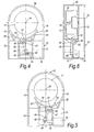
- the actuator 34 is located adjacent the back wall 12 to one side of the fan 17 as seen in Figure 6 .
- An arm 45 is mounted intermediate its ends on a fixed pivot 46 for rotation about an axis parallel to the fan axis 18 and is provided at one end with a fork 47 and at the other end with a slot 48.
- the slot 48 receives a pin 49 on the rod 35 and extending normal to the length of the rod 35.
- the fork 47 engages a second pin 50 carried on a boss 51 formed centrally on a shutter 52.
- the boss 51 includes a flange 53 that engages in a slot 54 formed in the housing 10 to constrain the shutter 52 to move in a rectilinear direction normal to the first and second side walls 14,15.
- the shutter 52 has an arcuate shutter wall 55 with a first extension surface 56 at one end and a second extension surface 57 at the other end.
- the connection between the arm 45 and the pin 50 on the boss 51 need not be via the fork 47. Any suitable connection, such as a slot, maybe used.
- the housing 10 is modified by the replacement of the planar front wall 13 with an arcuate front wall 58 which forms not only the front wall but also the equivalent of the arcuate housing wall 20 of Figure 1 , as seen in Figures 4 and 5 .
- the motor 32 and the actuator 34 are operated as described above.
- the shutter 52 is in the position shown in Figure 1 where the first end of the arcuate shutter wall 55 engages the second side wall 15 to close the second passage 23 and open the first passage 21.
- the second extension surface 57 engages the first interior wall 22 to form an extension of the first passage 21.
- the arcuate shutter wall 55 forms a continuation of the passage around the fan 15 providing a passage of increasing cross-section in a downstream direction.
- air passes to the first fragrance bottle (omitted for clarity from Figures 4 to 6 ) to release fragrance while the second passage 23 is closed.
- Reversal of the fan motor 32 and extension of the actuator rod 35 rotates the arm 45 around the pivot 46 with the fork 47 acting on the pin 50 to slide the boss 51 along the slot 54 to move the shutter 52 to the position shown in Figure 5 where the shutter 52 closes the first passage 21 and opens the second passage 23 with the second extension surface engaging the second interior wall 24 and forming an extension of the second passage 23.
- the arcuate shutter wall 55 forms a continuation of the passage around the fan 17 that increases in cross-section in a downstream direction.
- the third embodiment of the fragrance disperser has parts common with the second fragrance disperser. Those parts will be given the same reference numerals in the third fragrance disperser as in the second fragrance disperser and will not be described in detail.
- the actuator 34 is situated as described above with reference to Figures 4 to 6 .
- the connection between the actuator rod 35 and the shutter 52 is formed by a pair of parallel arms 60,61.
- Each arm 60,61 is at one end formed integrally with the shutter 52 to provide respective hinges 62,63 between the shutter 52 and the arm 60,61.
- the parts may be moulded together from a plastics material.
- the arms 60,61, at their ends opposite the shutter 52, are rotatably mounted on respective pivots 64,65 for rotation about respective axes parallel to the axis 18 of the fan 17.
- the arms 60,61 are parallel to one another.
- One arm 60 is formed with an extension 66 beyond the associated pivot 64 which is provided with a slot 67 receiving the pin 49 on the actuator rod 35.
- the fragrance disperser of Figures 7 to 9 operates in a similar way to the fragrance disperser of Figures 4 to 6 .
- the shutter 52 closes the second passage 23 and opens the first passage 21 as described above. Movement of the actuator rod 35 to the extended position shown in Figure 8 moves the shutter 52 to the position shown in Figure 8 where the first passage 21 is closed and the second passage 23 is open.
- the shutter 52 in the third form of fragrance disperser is not guided in rectilinear movement between the position shown in Figure 7 and Figure 8 . Rather, the shutter 52 is guided by the parallel arms 60,61.
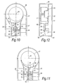
- the fourth form of the fragrance dispersing device has parts common with the second and third forms of the fragrance disperser shown in Figures 4 to 6 and 7 to 9 . Those parts will be given the same reference numerals in Figures 10 to 12 as they are in Figures 4 to 9 and will not be described in detail.
- the actuator 34 is located at a position somewhat spaced from the back wall 12 as seen in Figures 10, 11 and 12 .
- the shutter 52 is formed in one piece with an arm 70 that extends in a generally radial direction relative to the centre of curvature of the arcuate shutter wall 55 and thus generally radially relative to the axis 18 of the fan 17.
- the arm 70 has an end remote from the shutter 52 rotatable about an axis parallel to the fan axis 18 about a fixed pivot 71. Intermediate its ends, the arm 70 is provided with an elongated slot 72 that engages the pin 49 on the actuator rod 35.
- the arm 70 is also provided with two L-shaped spring arms 74 projecting from respective opposite sides of the arm 70 for cooperation with two stops 73 provided on the casing 11 in a manner to be discussed below.
- the fan motor 32 and the actuator 34 are operated as described above.
- the shutter 52 closes the second passage 23 and opens the first passage 21 so that fan air passes through the first passage 21 releasing fragrance.
- the actuator rod 35 is moved to the retracted position shown in Figure 11
- the shutter 52 moves to the position shown in Figure 11 where the first passage 21 is closed and the second passage 23 is opened so that fan air exits through the second passage 23 to release fragrance.
- the arm 70 pivots in either sense one of the spring arms 74 engages a respective stop 73 to provide spring damping of the movement of the arm 70 to avoid noise due to vibration/rattling.
- a shutter 38,52 to control the release of two fragrances has been described above with reference to the drawings in relation to a fan that is reversible. It will be appreciated that the fan 17 need not be reversible; the fan 17 could provide a continuous supply of air on rotation in a single sense only and the shutters 38,52 simply open and close the first and second passages 21,23 with the arrangement of the passages 21,23 and the shutter 38,52 being altered accordingly.
- the flow control of the air is performed by a shutter 38,52, it is possible to control the flow by means other than a shutter. For example, two separate shutters may be provided or the passages 21,23 may be opened and closed by other means such as louvres.
- the shutters 38,52 move between extreme positions, the shutters 38, 52, could move to one or more positions between the extreme positions to provide a required proportionate mixture of the fragrances.
- the embodiments described above with reference to Figures 1 to 12 use an electronically operated actuator 34 which extends and retracts a rod 35.
- the actuator could take any other form including a hydraulic actuator or any other suitable form of actuator.
Landscapes
- Health & Medical Sciences (AREA)
- Epidemiology (AREA)
- Life Sciences & Earth Sciences (AREA)
- Animal Behavior & Ethology (AREA)
- General Health & Medical Sciences (AREA)
- Public Health (AREA)
- Veterinary Medicine (AREA)
- Disinfection, Sterilisation Or Deodorisation Of Air (AREA)
- Structures Of Non-Positive Displacement Pumps (AREA)
- Air Bags (AREA)
- Fats And Perfumes (AREA)
- Packaging Of Annular Or Rod-Shaped Articles, Wearing Apparel, Cassettes, Or The Like (AREA)
Claims (22)
- Ein Duftspender aufweisend erste und zweite Duftquellen (25, 26), erste und zweite Strömungswege (21, 23), von denen jeder mit einer entsprechenden Duftquelle (25, 26) gekoppelt ist, einen Ventilator (17) zum Bereitstellen einer Luftströmung entlang der ersten und zweiten Strömungswege (21, 23), um die zugeordneten Duftstoffe freizugeben, und einen Flussregler (38, 52), der mittels eines Aktuators (34) zwischen einer ersten Position, in der die Luft entlang des ersten Strömungsweges (21) strömt, um die Freigabe des ersten Duftstoffes zu ermöglichen, und einer zweiten Position bewegbar ist, in der Luft entlang des zweiten Strömungsweges (23) strömt, um die Freigabe des zweiten Duftstoffes zu ermöglichen, dadurch gekennzeichnet, dass der Aktuator (34) mit dem Flussregler (38, 52) mittels eines Mechanismus verbunden ist, der die Betätigung des Aktuators (34) überträgt in eine Bewegung des Flussreglers (38, 52) zwischen der ersten und zweiten Position, welcher Mechanismus wenigstens einen Arm (36, 45, 60, 61, 70) aufweist, der zwischen dem Flussregler (38, 52) und dem Aktuator (34) eingebunden ist.
- Ein Spender nach Anspruch 1, bei dem die ersten und zweiten Strömungswege entsprechende erste und zweite Durchtritte (21, 23) aufweisen, wobei der Flussregler (38, 52) in dessen erster Position den ersten Durchtritt (21) öffnet und den zweiten Durchtritt (23) verschließt und in dessen zweiter Position den ersten Durchtritt (21) verschließt und den zweiten Durchtritt (23) öffnet.
- Ein Spender nach Anspruch 2, bei dem der erste Durchtritt (21) ein dem Ventilator (17) benachbartes Einlassende aufweist und der zweite Durchtritt (23) ein dem Ventilator (17) benachbartes Einlassende aufweist, wobei der Flussregler (38) die Einlassenden öffnet und schließt.
- Ein Spender nach einem der Ansprüche 1 bis 3, bei dem der Ventilator (17) in entsprechende entgegengesetzte erste und zweite Richtungen drehbetätigbar ist, wobei eine Drehbetätigung des Ventilators (17) in der ersten Richtung Luft durch den ersten Strömungsweg (21), mit dem Flussregler (38, 52) in der ersten Position, führt und eine Drehbetätigung des Ventilators (17) in der zweiten Richtung, mit dem Flussregler (38, 52) in der zweiten Position, Luft durch den zweiten Strömungsweg (23) führt.
- Ein Spender nach Anspruch 4 und aufweisend Steuermittel (42) zum Steuern des Aktuators (34) und des Ventilators (17) dergestalt, dass der Flussregler (38, 52) sich in der ersten Position befindet, wenn der Ventilator (17) in der ersten Richtung dreht und dass der Flussregler (38, 52) sich in der zweiten Position befindet, wenn der Ventilator (17) in der zweiten Richtung dreht.
- Ein Spender nach Anspruch 4 oder Anspruch 5, bei dem der Ventilator (17) innerhalb eines Gehäuses (10) angeordnet ist, wobei das Gehäuse (10) eine Wand (20) aufweist, die sich um den Ventilator (17) erstreckt und einen Weg für Luft definiert, der zu dem ersten Strömungsweg (21) und dem zweiten Strömungsweg (23) führt, wobei der Flussregler (38, 52) eine strömungsleitende Fläche (39, 55) aufweist, die sowohl in der ersten Position als auch in der zweiten Position eine stromabwärts gelegene Erweiterung der Gehäusewand (20) bereitstellt.
- Ein Spender nach Anspruch 6, bei dem der Ventilator (17) einen Außenumfang aufweist, die Gehäusewand (20) um eine Achse, die koaxial mit der Drehachse des Ventilators (17) ist, gebogen ist, die strömungsleitende Fläche (39, 55) gebogen ist und zusammen mit dem Außenumfang des Ventilators eine Passage ansteigenden Querschnitts in einer stromabwärts gelegenen Richtung ausbildet.
- Ein Spender nach Anspruch 6 oder Anspruch 7, bei dem der Flussregler (35, 52) eine erste Erweiterungsfläche (40) aufweist, die eine Fortsetzung des ersten Strömungsweges (21) ausbildet, wenn der Flussregler (38, 52) sich in der ersten Position befindet und eine zweite Eniveiterungsfläche (42) aufweist, die eine Fortsetzung des zweiten Strömungsweges (23) ausbildet, wenn der Flussregler (38, 52) sich in der zweiten Position befindet.
- Ein Spender nach einem der Ansprüche 1 bis 8, bei dem der Aktuator (34) einen Stab (35) aufweist, der zwischen ersten und zweiten Positionen bewegbar ist, um zu bewirken, dass der wenigstens eine Arm (36, 45, 60, 61, 70) den Flussregler (38, 52) zwischen der ersten und zweiten Position bewegt.
- Ein Spender nach Anspruch 9, bei dem der wenigstens eine Arm (36, 45, 60, 61, 70) gelenkig festgelegt ist, wobei die Bewegung des Stabs (35) den wenigstens einen Arm (36, 45, 60, 61, 70) um die Achse (37, 46, 64, 65, 49) verschwenkt.
- Ein Spender nach Anspruch 10, bei dem der wenigstens eine Arm (36, 70) ein erstes Ende und ein zweites Ende aufweist, wobei das erste Ende mit dem Flussregler (38, 52) verbunden ist und das zweite Ende gelenkig festgelegt ist, wobei der Stab (35) auf den Arm (36, 70) zwischen dessen Enden einwirkt.
- Ein Spender nach Anspruch 11, bei dem der Arm (70) sich von dem Ventilator (17) in einer im Wesentlichen radialen Richtung wegerstreckt.
- Ein Spender nach Anspruch 11, bei dem der Arm (36) auf einer Seite des Ventilators (17) angelenkt ist und sich der Flussregler (38) auf einer diametral gegenüberliegenden Seite des Ventilators (17) befindet, wobei sich der Arm (36) über den Ventilator (17) erstreckt.
- Ein Spender nach Anspruch 10, bei dem der wenigstens eine Arm (45, 60) ein erstes und ein zweites Ende aufweist und gelenkig zwischen dem ersten und zweiten Ende festgelegt ist, wobei das erste Ende mit dem Flussregler (52) gelenkig verbunden ist und das zweite Ende mit der Stange (35) gelenkig verbunden ist.
- Ein Spender nach Anspruch 14, bei dem der wenigstens eine Arm (45, 60) sich von dem Ventilator (17) in einer im Wesentlichen radialen Richtung wegerstreckt.
- Ein Spender nach Anspruch 9, bei dem der wenigstens eine Arm (60) einer von zwei parallelen Armen (60, 61) ist, wobei jeder Arm (60, 61) ein erstes Ende und ein zweites Ende aufweist, wobei die ersten Enden des Arms (60, 61) mit dem Flussregler (52) gelenkig verbunden sind und die zweiten Enden der Arme (60, 61) mit beabstandet angeordneten Achsen (64, 65) verbunden sind, wobei die Stange (35) auf einen der Arme (60) wirkt.
- Ein Spender nach einem der Ansprüche 1 bis 16, bei dem der Ventilator (17) innerhalb eines Gehäuses (10) angeordnet ist, wobei das Gehäuse eine den Ventilator aufnehmende Kammer und erste und zweite Durchtritte (21, 23) aufweist, die von dem Gehäuse (10) ausgehen und entsprechend den ersten und zweiten Strömungsweg ausbilden.
- Ein Spender nach Anspruch 17, bei dem die Kammer eine gebogene Wand (20) aufweist, die den Ventilator (17) teilweise umgibt, wobei die gebogene Wand ein erstes Ende und ein zweites Ende aufweist, wobei der erste Durchtritt (21) von dem ersten Ende der gebogenen Wand (20) ausgeht und der zweite Durchtritt (23) von dem zweiten Ende der gebogenen Wand (20) ausgeht.
- Ein Spender nach Anspruch 17 oder Anspruch 18, bei dem die ersten und zweiten Durchtritte (21, 23) nebeneinander in dem Gehäuse (10) angeordnet sind.
- Ein Spender nach einem der Ansprüche 1 bis 19, bei dem der Aktuator (34) elektronisch betätigt ist.
- Ein Spender nach einem der Ansprüche 1 bis 20, bei dem der Flussregler (38, 52) mittels des Aktuators (34) in wenigstens eine Position zwischen der ersten und zweiten Position bewegbar ist, um einen anteiligen Anstieg beider Duftstoffe bereitzustellen.
- Ein Spender nach einem der Ansprüche 1 bis 21, bei dem der Flussregler (38, 52) in der ersten Position die Freigabe des zweiten Duftstoffes verhindert und in der zweiten Position die Freigabe des ersten Duftstoffes verhindert.
Applications Claiming Priority (2)
| Application Number | Priority Date | Filing Date | Title |
|---|---|---|---|
| GB0309624A GB2401047B (en) | 2003-04-28 | 2003-04-28 | Fragrance dispersers |
| PCT/GB2004/001754 WO2004096300A1 (en) | 2003-04-28 | 2004-04-27 | Fragrance dispersers |
Publications (2)
| Publication Number | Publication Date |
|---|---|
| EP1620137A1 EP1620137A1 (de) | 2006-02-01 |
| EP1620137B1 true EP1620137B1 (de) | 2011-06-08 |
Family
ID=9957268
Family Applications (1)
| Application Number | Title | Priority Date | Filing Date |
|---|---|---|---|
| EP04729669A Expired - Lifetime EP1620137B1 (de) | 2003-04-28 | 2004-04-27 | Duftspender |
Country Status (8)
| Country | Link |
|---|---|
| US (1) | US7621511B2 (de) |
| EP (1) | EP1620137B1 (de) |
| AT (1) | ATE511863T1 (de) |
| AU (1) | AU2004233636B2 (de) |
| CA (1) | CA2532002C (de) |
| ES (1) | ES2370349T3 (de) |
| GB (1) | GB2401047B (de) |
| WO (1) | WO2004096300A1 (de) |
Families Citing this family (35)
| Publication number | Priority date | Publication date | Assignee | Title |
|---|---|---|---|---|
| US7469844B2 (en) | 2002-11-08 | 2008-12-30 | S.C. Johnson & Son, Inc. | Diffusion device and method of diffusing |
| US7389943B2 (en) | 2004-06-30 | 2008-06-24 | S.C. Johnson & Son, Inc. | Electromechanical apparatus for dispensing volatile substances with single dispensing mechanism and cartridge for holding multiple receptacles |
| GB0500481D0 (en) * | 2005-01-12 | 2005-02-16 | Givaudan Sa | Device |
| GB2423930A (en) * | 2005-03-11 | 2006-09-13 | Reckitt Benckiser | Emanation or fragrancing device |
| GB0505173D0 (en) * | 2005-03-15 | 2005-04-20 | Givaudan Sa | Apparatus |
| US7622073B2 (en) | 2005-04-12 | 2009-11-24 | S.C. Johnson & Son, Inc. | Apparatus for and method of dispensing active materials |
| GB2432316A (en) * | 2005-09-15 | 2007-05-23 | Carbonate Ltd | Heated wick assemblies |
| FR2891443B1 (fr) * | 2005-10-05 | 2007-12-28 | Dynamic Up Sarl | Appareil diffuseur autonome a cartouches rechargeables de produits cosmetiques et son embout de protection deformable. |
| NL1030571C2 (nl) * | 2005-12-01 | 2006-04-27 | Sara Lee De Nv | Geurafgiftesysteem. |
| GB2432789B (en) * | 2005-12-01 | 2011-08-10 | Sara Lee De Nv | Fragrance delivery system |
| WO2007064189A1 (en) * | 2005-12-01 | 2007-06-07 | Sara Lee/De N.V. | Fragrance delivery system |
| US7493028B2 (en) | 2006-04-04 | 2009-02-17 | Group Dekko, Inc. | Multiple bottle evaporative diffuser |
| US7734159B2 (en) * | 2006-08-31 | 2010-06-08 | S.C. Johnson & Son, Inc. | Dispersion device for dispersing multiple volatile materials |
| EP1902736A1 (de) * | 2006-09-19 | 2008-03-26 | Sara Lee/DE N.V. | Lufterfrischer zum Verströmen zweier Düfte |
| GB0622876D0 (en) * | 2006-11-16 | 2006-12-27 | Givaudan Sa | Device |
| DE102006061825A1 (de) * | 2006-12-21 | 2008-06-26 | Behr Gmbh & Co. Kg | Beduftungssystem, insbesondere für ein Kraftfahrzeug |
| US7840123B2 (en) | 2007-06-21 | 2010-11-23 | S.C. Johnson & Son, Inc. | Diffusion device |
| US20080315005A1 (en) * | 2007-06-25 | 2008-12-25 | Michaels Kenneth W | Active material emitting device and method of dispensing an active material |
| US7833492B2 (en) * | 2007-07-03 | 2010-11-16 | S.C. Johnson & Son, Inc. | Wearable chemical dispenser |
| CN101687054B (zh) * | 2007-07-03 | 2014-01-01 | 贝洱两合公司 | 用于汽车的空气清新装置 |
| DE102007050321A1 (de) * | 2007-10-18 | 2009-04-23 | Stefan Wohnhas | Vorrichtung zur dosierten Abgabe eines oder mehrerer Duftstoffe in einem geschlossenen Raum, insbesondere in einer Kabine eines Fahrzeugs |
| US8320751B2 (en) * | 2007-12-20 | 2012-11-27 | S.C. Johnson & Son, Inc. | Volatile material diffuser and method of preventing undesirable mixing of volatile materials |
| US20100044468A1 (en) * | 2008-06-26 | 2010-02-25 | Momentum Industries, Llc | Device for distributing volatile fluids in air |
| KR101423198B1 (ko) | 2008-10-14 | 2014-07-25 | 한라비스테온공조 주식회사 | 차량용 공조장치의 방향제 발생장치 |
| US9364574B2 (en) * | 2009-08-14 | 2016-06-14 | S. C. Johnson & Son, Inc. | Wearable chemical dispenser |
| USD639923S1 (en) | 2010-04-15 | 2011-06-14 | S.C. Johnson & Son, Inc. | Dispensing device |
| US8524158B2 (en) | 2011-05-11 | 2013-09-03 | S. C. Johnson & Son, Inc. | Wearable chemical dispenser with useful life indicator |
| US8622246B2 (en) | 2012-02-13 | 2014-01-07 | Ecolab Usa Inc. | Fluid reservoir docking station |
| US9080714B2 (en) | 2012-11-20 | 2015-07-14 | Kenu, Inc. | Adjustable portable device holder |
| DE102012224497A1 (de) * | 2012-12-28 | 2014-07-03 | Behr Gmbh & Co. Kg | Beduftungsvorrichtung |
| GB201303903D0 (en) * | 2013-03-05 | 2013-04-17 | Quantex Patents Ltd | Pumps |
| US9149031B2 (en) | 2013-09-13 | 2015-10-06 | S.C. Johnson & Son, Inc. | Portable area repellent device |
| US9352062B2 (en) | 2013-10-30 | 2016-05-31 | S.C. Johnson & Son, Inc. | Wearable chemical dispenser |
| US9352064B2 (en) | 2014-06-05 | 2016-05-31 | S. C. Johnson & Son, Inc. | Wearable chemical dispenser |
| US10265431B2 (en) | 2017-06-08 | 2019-04-23 | Henkel IP & Holding GmbH | Volatile diffuser pods and related systems |
Family Cites Families (12)
| Publication number | Priority date | Publication date | Assignee | Title |
|---|---|---|---|---|
| US3711023A (en) * | 1971-03-26 | 1973-01-16 | D Smith | Device for controlling the evaporation of volatile substances particularly for use in air conditioning systems |
| GB2118636A (en) | 1982-04-15 | 1983-11-02 | Christmas Inc Mr | Fan |
| US4603030A (en) * | 1984-09-20 | 1986-07-29 | Mccarthy Robert E | Scent-Emitting Systems |
| CA1318285C (en) * | 1987-06-10 | 1993-05-25 | Hiroji Machida | Method for supplying aromas, apparatus therefore and facilities provided with same |
| US5259062A (en) * | 1990-04-24 | 1993-11-02 | Pelko Electric Corporation | Air treatment apparatus utilizing interchangeable cartridges |
| US5167877A (en) * | 1991-12-10 | 1992-12-01 | Pai Wen Chung | Air purifier with perfume dispensing control |
| US6234455B1 (en) * | 1994-06-30 | 2001-05-22 | Gotz-Ulrich Wittek | Device and process for delivering substances for dispersal in the air |
| US5565148A (en) * | 1995-03-16 | 1996-10-15 | Minnesota Mining And Manufacturing Company | Device for selectively providing a multiplicity of aromas |
| ATE240125T1 (de) * | 1997-07-11 | 2003-05-15 | Hts Int Trading Ag | Verdunstungs-dispenser |
| WO2000012143A1 (en) * | 1998-08-28 | 2000-03-09 | Aroma Technology Limited | Odor dispensing device and odor dispensing cartridge |
| GB0123851D0 (en) * | 2001-10-04 | 2001-11-28 | Pankhurst Design & Development | Dispersing fragrances |
| US7036800B2 (en) * | 2002-04-08 | 2006-05-02 | Ellis Earle R | Automatically controlling the interaction of a medium with an external environment |
-
2003
- 2003-04-28 GB GB0309624A patent/GB2401047B/en not_active Expired - Fee Related
-
2004
- 2004-04-27 AT AT04729669T patent/ATE511863T1/de not_active IP Right Cessation
- 2004-04-27 CA CA2532002A patent/CA2532002C/en not_active Expired - Fee Related
- 2004-04-27 ES ES04729669T patent/ES2370349T3/es not_active Expired - Lifetime
- 2004-04-27 US US10/568,069 patent/US7621511B2/en not_active Expired - Fee Related
- 2004-04-27 AU AU2004233636A patent/AU2004233636B2/en not_active Ceased
- 2004-04-27 EP EP04729669A patent/EP1620137B1/de not_active Expired - Lifetime
- 2004-04-27 WO PCT/GB2004/001754 patent/WO2004096300A1/en not_active Ceased
Also Published As
| Publication number | Publication date |
|---|---|
| WO2004096300A1 (en) | 2004-11-11 |
| CA2532002A1 (en) | 2004-11-11 |
| GB2401047B (en) | 2006-03-15 |
| GB0309624D0 (en) | 2003-06-04 |
| EP1620137A1 (de) | 2006-02-01 |
| US7621511B2 (en) | 2009-11-24 |
| ATE511863T1 (de) | 2011-06-15 |
| ES2370349T3 (es) | 2011-12-14 |
| US20070036688A1 (en) | 2007-02-15 |
| AU2004233636B2 (en) | 2010-06-03 |
| CA2532002C (en) | 2011-09-13 |
| GB2401047A (en) | 2004-11-03 |
| AU2004233636A1 (en) | 2004-11-11 |
Similar Documents
| Publication | Publication Date | Title |
|---|---|---|
| US7621511B2 (en) | Fragrance dispensers | |
| CN105650980B (zh) | 冰箱及用于冰箱的分路送风装置 | |
| CN110319563B (zh) | 空调器 | |
| CN112413727B (zh) | 空调器 | |
| CN106286327A (zh) | 离心风机 | |
| CN108302874A (zh) | 分路送风装置及冰箱 | |
| CN108302873A (zh) | 分路送风装置及冰箱 | |
| GB2153014A (en) | Automatically shuttered ventilator | |
| CN104896837B (zh) | 分路送风装置 | |
| US7326108B2 (en) | Ventilation device | |
| CN111623412A (zh) | 室内机、空调器及空调器控制方法 | |
| CN204806780U (zh) | 分路送风装置及具有该分路送风装置的冰箱 | |
| CN113959001A (zh) | 室内机、空调器及空调器控制的方法 | |
| CN210123179U (zh) | 空调器 | |
| JP6262461B2 (ja) | 空気調和装置 | |
| CN212841893U (zh) | 室内机、空调器 | |
| GB2438761A (en) | Ventilation device with a rotatable shutter | |
| JP2529518B2 (ja) | ラインディフュ―ザの風量調節装置 | |
| EP1531307B1 (de) | Belüftungsvorrichtung | |
| KR101095074B1 (ko) | 공기배출 조절장치 | |
| CN101187485B (zh) | 气流引导装置及具有该装置的空调机 | |
| SU1649217A1 (ru) | Воздухораспределитель | |
| JPS6033210B2 (ja) | ダクト用換気扇 | |
| US20050194002A1 (en) | Adjustable air bypass system for heating appliance | |
| JPH0742989A (ja) | 熱交換形換気扇 |
Legal Events
| Date | Code | Title | Description |
|---|---|---|---|
| PUAI | Public reference made under article 153(3) epc to a published international application that has entered the european phase |
Free format text: ORIGINAL CODE: 0009012 |
|
| 17P | Request for examination filed |
Effective date: 20051128 |
|
| AK | Designated contracting states |
Kind code of ref document: A1 Designated state(s): AT BE BG CH CY CZ DE DK EE ES FI FR GB GR HU IE IT LI LU MC NL PL PT RO SE SI SK TR |
|
| DAX | Request for extension of the european patent (deleted) | ||
| RAP1 | Party data changed (applicant data changed or rights of an application transferred) |
Owner name: PDD INNOVATIONS LTD. |
|
| RAP1 | Party data changed (applicant data changed or rights of an application transferred) |
Owner name: CARBONATE LIMITED |
|
| RAP1 | Party data changed (applicant data changed or rights of an application transferred) |
Owner name: CTR CONSULTORIA TECNICA E REPRESENTACOES, LDA. |
|
| GRAP | Despatch of communication of intention to grant a patent |
Free format text: ORIGINAL CODE: EPIDOSNIGR1 |
|
| GRAS | Grant fee paid |
Free format text: ORIGINAL CODE: EPIDOSNIGR3 |
|
| GRAA | (expected) grant |
Free format text: ORIGINAL CODE: 0009210 |
|
| AK | Designated contracting states |
Kind code of ref document: B1 Designated state(s): AT BE BG CH CY CZ DE DK EE ES FI FR GB GR HU IE IT LI LU MC NL PL PT RO SE SI SK TR |
|
| REG | Reference to a national code |
Ref country code: GB Ref legal event code: FG4D |
|
| REG | Reference to a national code |
Ref country code: CH Ref legal event code: EP |
|
| REG | Reference to a national code |
Ref country code: IE Ref legal event code: FG4D |
|
| REG | Reference to a national code |
Ref country code: DE Ref legal event code: R096 Ref document number: 602004032975 Country of ref document: DE Effective date: 20110721 |
|
| REG | Reference to a national code |
Ref country code: NL Ref legal event code: VDEP Effective date: 20110608 |
|
| PG25 | Lapsed in a contracting state [announced via postgrant information from national office to epo] |
Ref country code: SE Free format text: LAPSE BECAUSE OF FAILURE TO SUBMIT A TRANSLATION OF THE DESCRIPTION OR TO PAY THE FEE WITHIN THE PRESCRIBED TIME-LIMIT Effective date: 20110608 |
|
| PG25 | Lapsed in a contracting state [announced via postgrant information from national office to epo] |
Ref country code: GR Free format text: LAPSE BECAUSE OF FAILURE TO SUBMIT A TRANSLATION OF THE DESCRIPTION OR TO PAY THE FEE WITHIN THE PRESCRIBED TIME-LIMIT Effective date: 20110909 Ref country code: SI Free format text: LAPSE BECAUSE OF FAILURE TO SUBMIT A TRANSLATION OF THE DESCRIPTION OR TO PAY THE FEE WITHIN THE PRESCRIBED TIME-LIMIT Effective date: 20110608 Ref country code: AT Free format text: LAPSE BECAUSE OF FAILURE TO SUBMIT A TRANSLATION OF THE DESCRIPTION OR TO PAY THE FEE WITHIN THE PRESCRIBED TIME-LIMIT Effective date: 20110608 Ref country code: FI Free format text: LAPSE BECAUSE OF FAILURE TO SUBMIT A TRANSLATION OF THE DESCRIPTION OR TO PAY THE FEE WITHIN THE PRESCRIBED TIME-LIMIT Effective date: 20110608 Ref country code: CY Free format text: LAPSE BECAUSE OF FAILURE TO SUBMIT A TRANSLATION OF THE DESCRIPTION OR TO PAY THE FEE WITHIN THE PRESCRIBED TIME-LIMIT Effective date: 20110608 |
|
| REG | Reference to a national code |
Ref country code: ES Ref legal event code: FG2A Ref document number: 2370349 Country of ref document: ES Kind code of ref document: T3 Effective date: 20111214 |
|
| PG25 | Lapsed in a contracting state [announced via postgrant information from national office to epo] |
Ref country code: BE Free format text: LAPSE BECAUSE OF FAILURE TO SUBMIT A TRANSLATION OF THE DESCRIPTION OR TO PAY THE FEE WITHIN THE PRESCRIBED TIME-LIMIT Effective date: 20110608 Ref country code: NL Free format text: LAPSE BECAUSE OF FAILURE TO SUBMIT A TRANSLATION OF THE DESCRIPTION OR TO PAY THE FEE WITHIN THE PRESCRIBED TIME-LIMIT Effective date: 20110608 |
|
| PG25 | Lapsed in a contracting state [announced via postgrant information from national office to epo] |
Ref country code: EE Free format text: LAPSE BECAUSE OF FAILURE TO SUBMIT A TRANSLATION OF THE DESCRIPTION OR TO PAY THE FEE WITHIN THE PRESCRIBED TIME-LIMIT Effective date: 20110608 Ref country code: PT Free format text: LAPSE BECAUSE OF FAILURE TO SUBMIT A TRANSLATION OF THE DESCRIPTION OR TO PAY THE FEE WITHIN THE PRESCRIBED TIME-LIMIT Effective date: 20111010 Ref country code: CZ Free format text: LAPSE BECAUSE OF FAILURE TO SUBMIT A TRANSLATION OF THE DESCRIPTION OR TO PAY THE FEE WITHIN THE PRESCRIBED TIME-LIMIT Effective date: 20110608 |
|
| PG25 | Lapsed in a contracting state [announced via postgrant information from national office to epo] |
Ref country code: SK Free format text: LAPSE BECAUSE OF FAILURE TO SUBMIT A TRANSLATION OF THE DESCRIPTION OR TO PAY THE FEE WITHIN THE PRESCRIBED TIME-LIMIT Effective date: 20110608 Ref country code: RO Free format text: LAPSE BECAUSE OF FAILURE TO SUBMIT A TRANSLATION OF THE DESCRIPTION OR TO PAY THE FEE WITHIN THE PRESCRIBED TIME-LIMIT Effective date: 20110608 Ref country code: PL Free format text: LAPSE BECAUSE OF FAILURE TO SUBMIT A TRANSLATION OF THE DESCRIPTION OR TO PAY THE FEE WITHIN THE PRESCRIBED TIME-LIMIT Effective date: 20110608 |
|
| PLBE | No opposition filed within time limit |
Free format text: ORIGINAL CODE: 0009261 |
|
| STAA | Information on the status of an ep patent application or granted ep patent |
Free format text: STATUS: NO OPPOSITION FILED WITHIN TIME LIMIT |
|
| 26N | No opposition filed |
Effective date: 20120309 |
|
| PG25 | Lapsed in a contracting state [announced via postgrant information from national office to epo] |
Ref country code: DK Free format text: LAPSE BECAUSE OF FAILURE TO SUBMIT A TRANSLATION OF THE DESCRIPTION OR TO PAY THE FEE WITHIN THE PRESCRIBED TIME-LIMIT Effective date: 20110608 |
|
| REG | Reference to a national code |
Ref country code: DE Ref legal event code: R097 Ref document number: 602004032975 Country of ref document: DE Effective date: 20120309 |
|
| PG25 | Lapsed in a contracting state [announced via postgrant information from national office to epo] |
Ref country code: MC Free format text: LAPSE BECAUSE OF NON-PAYMENT OF DUE FEES Effective date: 20120430 |
|
| REG | Reference to a national code |
Ref country code: CH Ref legal event code: PL |
|
| PG25 | Lapsed in a contracting state [announced via postgrant information from national office to epo] |
Ref country code: LI Free format text: LAPSE BECAUSE OF NON-PAYMENT OF DUE FEES Effective date: 20120430 Ref country code: CH Free format text: LAPSE BECAUSE OF NON-PAYMENT OF DUE FEES Effective date: 20120430 |
|
| PG25 | Lapsed in a contracting state [announced via postgrant information from national office to epo] |
Ref country code: IE Free format text: LAPSE BECAUSE OF NON-PAYMENT OF DUE FEES Effective date: 20120427 |
|
| PG25 | Lapsed in a contracting state [announced via postgrant information from national office to epo] |
Ref country code: BG Free format text: LAPSE BECAUSE OF FAILURE TO SUBMIT A TRANSLATION OF THE DESCRIPTION OR TO PAY THE FEE WITHIN THE PRESCRIBED TIME-LIMIT Effective date: 20110908 |
|
| PG25 | Lapsed in a contracting state [announced via postgrant information from national office to epo] |
Ref country code: TR Free format text: LAPSE BECAUSE OF FAILURE TO SUBMIT A TRANSLATION OF THE DESCRIPTION OR TO PAY THE FEE WITHIN THE PRESCRIBED TIME-LIMIT Effective date: 20110608 |
|
| PG25 | Lapsed in a contracting state [announced via postgrant information from national office to epo] |
Ref country code: LU Free format text: LAPSE BECAUSE OF NON-PAYMENT OF DUE FEES Effective date: 20120427 |
|
| PG25 | Lapsed in a contracting state [announced via postgrant information from national office to epo] |
Ref country code: HU Free format text: LAPSE BECAUSE OF FAILURE TO SUBMIT A TRANSLATION OF THE DESCRIPTION OR TO PAY THE FEE WITHIN THE PRESCRIBED TIME-LIMIT Effective date: 20040427 |
|
| PGFP | Annual fee paid to national office [announced via postgrant information from national office to epo] |
Ref country code: GB Payment date: 20140423 Year of fee payment: 11 |
|
| PGFP | Annual fee paid to national office [announced via postgrant information from national office to epo] |
Ref country code: IT Payment date: 20140422 Year of fee payment: 11 Ref country code: ES Payment date: 20140425 Year of fee payment: 11 Ref country code: DE Payment date: 20140618 Year of fee payment: 11 |
|
| PGFP | Annual fee paid to national office [announced via postgrant information from national office to epo] |
Ref country code: FR Payment date: 20140829 Year of fee payment: 11 |
|
| REG | Reference to a national code |
Ref country code: DE Ref legal event code: R119 Ref document number: 602004032975 Country of ref document: DE |
|
| GBPC | Gb: european patent ceased through non-payment of renewal fee |
Effective date: 20150427 |
|
| PG25 | Lapsed in a contracting state [announced via postgrant information from national office to epo] |
Ref country code: DE Free format text: LAPSE BECAUSE OF NON-PAYMENT OF DUE FEES Effective date: 20151103 Ref country code: IT Free format text: LAPSE BECAUSE OF NON-PAYMENT OF DUE FEES Effective date: 20150427 Ref country code: GB Free format text: LAPSE BECAUSE OF NON-PAYMENT OF DUE FEES Effective date: 20150427 |
|
| REG | Reference to a national code |
Ref country code: FR Ref legal event code: ST Effective date: 20151231 |
|
| PG25 | Lapsed in a contracting state [announced via postgrant information from national office to epo] |
Ref country code: FR Free format text: LAPSE BECAUSE OF NON-PAYMENT OF DUE FEES Effective date: 20150430 |
|
| REG | Reference to a national code |
Ref country code: ES Ref legal event code: FD2A Effective date: 20160829 |
|
| PG25 | Lapsed in a contracting state [announced via postgrant information from national office to epo] |
Ref country code: ES Free format text: LAPSE BECAUSE OF NON-PAYMENT OF DUE FEES Effective date: 20150428 |