EP1620157B1 - Führungsdraht mit einem biegesegment - Google Patents
Führungsdraht mit einem biegesegment Download PDFInfo
- Publication number
- EP1620157B1 EP1620157B1 EP04749610A EP04749610A EP1620157B1 EP 1620157 B1 EP1620157 B1 EP 1620157B1 EP 04749610 A EP04749610 A EP 04749610A EP 04749610 A EP04749610 A EP 04749610A EP 1620157 B1 EP1620157 B1 EP 1620157B1
- Authority
- EP
- European Patent Office
- Prior art keywords
- segment
- guide wire
- wire structure
- guide
- wire
- Prior art date
- Legal status (The legal status is an assumption and is not a legal conclusion. Google has not performed a legal analysis and makes no representation as to the accuracy of the status listed.)
- Expired - Lifetime
Links
- 238000005452 bending Methods 0.000 title claims abstract description 19
- HLXZNVUGXRDIFK-UHFFFAOYSA-N nickel titanium Chemical compound [Ti].[Ti].[Ti].[Ti].[Ti].[Ti].[Ti].[Ti].[Ti].[Ti].[Ti].[Ni].[Ni].[Ni].[Ni].[Ni].[Ni].[Ni].[Ni].[Ni].[Ni].[Ni].[Ni].[Ni].[Ni] HLXZNVUGXRDIFK-UHFFFAOYSA-N 0.000 claims description 6
- 229910001000 nickel titanium Inorganic materials 0.000 claims description 6
- 238000003780 insertion Methods 0.000 claims description 4
- 230000037431 insertion Effects 0.000 claims description 4
- 230000003247 decreasing effect Effects 0.000 claims 2
- 210000001035 gastrointestinal tract Anatomy 0.000 description 24
- 239000000463 material Substances 0.000 description 16
- 210000001072 colon Anatomy 0.000 description 12
- 238000005520 cutting process Methods 0.000 description 11
- 238000000034 method Methods 0.000 description 11
- 210000001519 tissue Anatomy 0.000 description 6
- 239000003086 colorant Substances 0.000 description 5
- 230000006378 damage Effects 0.000 description 5
- 238000001574 biopsy Methods 0.000 description 4
- 239000002783 friction material Substances 0.000 description 4
- 230000033001 locomotion Effects 0.000 description 4
- 230000000694 effects Effects 0.000 description 3
- 230000004048 modification Effects 0.000 description 3
- 238000012986 modification Methods 0.000 description 3
- 230000003287 optical effect Effects 0.000 description 3
- 230000007704 transition Effects 0.000 description 3
- XLYOFNOQVPJJNP-UHFFFAOYSA-N water Substances O XLYOFNOQVPJJNP-UHFFFAOYSA-N 0.000 description 3
- 210000000436 anus Anatomy 0.000 description 2
- 230000008901 benefit Effects 0.000 description 2
- 230000002496 gastric effect Effects 0.000 description 2
- 238000011065 in-situ storage Methods 0.000 description 2
- 210000000713 mesentery Anatomy 0.000 description 2
- 239000004033 plastic Substances 0.000 description 2
- 229920003023 plastic Polymers 0.000 description 2
- 229920001296 polysiloxane Polymers 0.000 description 2
- 230000002441 reversible effect Effects 0.000 description 2
- 229910001220 stainless steel Inorganic materials 0.000 description 2
- 230000000007 visual effect Effects 0.000 description 2
- 241001465754 Metazoa Species 0.000 description 1
- 206010028980 Neoplasm Diseases 0.000 description 1
- 208000037062 Polyps Diseases 0.000 description 1
- 229910000831 Steel Inorganic materials 0.000 description 1
- 208000034940 Undiagnosed disease Diseases 0.000 description 1
- 208000027418 Wounds and injury Diseases 0.000 description 1
- 230000009471 action Effects 0.000 description 1
- 238000004026 adhesive bonding Methods 0.000 description 1
- 229910045601 alloy Inorganic materials 0.000 description 1
- 239000000956 alloy Substances 0.000 description 1
- 210000003484 anatomy Anatomy 0.000 description 1
- 210000001367 artery Anatomy 0.000 description 1
- 230000001174 ascending effect Effects 0.000 description 1
- 239000000560 biocompatible material Substances 0.000 description 1
- 230000015572 biosynthetic process Effects 0.000 description 1
- 201000011510 cancer Diseases 0.000 description 1
- 210000004534 cecum Anatomy 0.000 description 1
- 230000008859 change Effects 0.000 description 1
- 230000002301 combined effect Effects 0.000 description 1
- 230000006835 compression Effects 0.000 description 1
- 238000007906 compression Methods 0.000 description 1
- 238000002788 crimping Methods 0.000 description 1
- 239000003814 drug Substances 0.000 description 1
- 229940079593 drug Drugs 0.000 description 1
- 210000001198 duodenum Anatomy 0.000 description 1
- 230000002526 effect on cardiovascular system Effects 0.000 description 1
- 210000003238 esophagus Anatomy 0.000 description 1
- 239000003365 glass fiber Substances 0.000 description 1
- 238000003384 imaging method Methods 0.000 description 1
- 208000014674 injury Diseases 0.000 description 1
- 238000003973 irrigation Methods 0.000 description 1
- 230000002262 irrigation Effects 0.000 description 1
- 238000005304 joining Methods 0.000 description 1
- 235000021184 main course Nutrition 0.000 description 1
- 230000007246 mechanism Effects 0.000 description 1
- 239000002184 metal Substances 0.000 description 1
- 210000001640 nerve ending Anatomy 0.000 description 1
- 229920000728 polyester Polymers 0.000 description 1
- 229920001343 polytetrafluoroethylene Polymers 0.000 description 1
- 239000004810 polytetrafluoroethylene Substances 0.000 description 1
- 230000008569 process Effects 0.000 description 1
- 210000000664 rectum Anatomy 0.000 description 1
- 210000001599 sigmoid colon Anatomy 0.000 description 1
- 210000000813 small intestine Anatomy 0.000 description 1
- 229910000679 solder Inorganic materials 0.000 description 1
- 239000010959 steel Substances 0.000 description 1
- 210000002784 stomach Anatomy 0.000 description 1
- 238000003860 storage Methods 0.000 description 1
- 239000000126 substance Substances 0.000 description 1
- 238000006467 substitution reaction Methods 0.000 description 1
- 238000002560 therapeutic procedure Methods 0.000 description 1
- 210000003384 transverse colon Anatomy 0.000 description 1
- 230000002792 vascular Effects 0.000 description 1
- 210000003462 vein Anatomy 0.000 description 1
- 238000012800 visualization Methods 0.000 description 1
- 238000003466 welding Methods 0.000 description 1
Images


Classifications
-
- A—HUMAN NECESSITIES
- A61—MEDICAL OR VETERINARY SCIENCE; HYGIENE
- A61M—DEVICES FOR INTRODUCING MEDIA INTO, OR ONTO, THE BODY; DEVICES FOR TRANSDUCING BODY MEDIA OR FOR TAKING MEDIA FROM THE BODY; DEVICES FOR PRODUCING OR ENDING SLEEP OR STUPOR
- A61M25/00—Catheters; Hollow probes
- A61M25/01—Introducing, guiding, advancing, emplacing or holding catheters
- A61M25/09—Guide wires
-
- A—HUMAN NECESSITIES
- A61—MEDICAL OR VETERINARY SCIENCE; HYGIENE
- A61M—DEVICES FOR INTRODUCING MEDIA INTO, OR ONTO, THE BODY; DEVICES FOR TRANSDUCING BODY MEDIA OR FOR TAKING MEDIA FROM THE BODY; DEVICES FOR PRODUCING OR ENDING SLEEP OR STUPOR
- A61M25/00—Catheters; Hollow probes
- A61M25/0021—Catheters; Hollow probes characterised by the form of the tubing
- A61M25/0023—Catheters; Hollow probes characterised by the form of the tubing by the form of the lumen, e.g. cross-section, variable diameter
- A61M25/0026—Multi-lumen catheters with stationary elements
-
- A—HUMAN NECESSITIES
- A61—MEDICAL OR VETERINARY SCIENCE; HYGIENE
- A61M—DEVICES FOR INTRODUCING MEDIA INTO, OR ONTO, THE BODY; DEVICES FOR TRANSDUCING BODY MEDIA OR FOR TAKING MEDIA FROM THE BODY; DEVICES FOR PRODUCING OR ENDING SLEEP OR STUPOR
- A61M25/00—Catheters; Hollow probes
- A61M25/0067—Catheters; Hollow probes characterised by the distal end, e.g. tips
- A61M25/0082—Catheter tip comprising a tool
-
- A—HUMAN NECESSITIES
- A61—MEDICAL OR VETERINARY SCIENCE; HYGIENE
- A61M—DEVICES FOR INTRODUCING MEDIA INTO, OR ONTO, THE BODY; DEVICES FOR TRANSDUCING BODY MEDIA OR FOR TAKING MEDIA FROM THE BODY; DEVICES FOR PRODUCING OR ENDING SLEEP OR STUPOR
- A61M25/00—Catheters; Hollow probes
- A61M25/01—Introducing, guiding, advancing, emplacing or holding catheters
- A61M25/09—Guide wires
- A61M2025/09133—Guide wires having specific material compositions or coatings; Materials with specific mechanical behaviours, e.g. stiffness, strength to transmit torque
- A61M2025/09141—Guide wires having specific material compositions or coatings; Materials with specific mechanical behaviours, e.g. stiffness, strength to transmit torque made of shape memory alloys which take a particular shape at a certain temperature
-
- A—HUMAN NECESSITIES
- A61—MEDICAL OR VETERINARY SCIENCE; HYGIENE
- A61M—DEVICES FOR INTRODUCING MEDIA INTO, OR ONTO, THE BODY; DEVICES FOR TRANSDUCING BODY MEDIA OR FOR TAKING MEDIA FROM THE BODY; DEVICES FOR PRODUCING OR ENDING SLEEP OR STUPOR
- A61M2210/00—Anatomical parts of the body
- A61M2210/10—Trunk
- A61M2210/1042—Alimentary tract
- A61M2210/1064—Large intestine
-
- A—HUMAN NECESSITIES
- A61—MEDICAL OR VETERINARY SCIENCE; HYGIENE
- A61M—DEVICES FOR INTRODUCING MEDIA INTO, OR ONTO, THE BODY; DEVICES FOR TRANSDUCING BODY MEDIA OR FOR TAKING MEDIA FROM THE BODY; DEVICES FOR PRODUCING OR ENDING SLEEP OR STUPOR
- A61M2210/00—Anatomical parts of the body
- A61M2210/10—Trunk
- A61M2210/1042—Alimentary tract
- A61M2210/1067—Anus
-
- A—HUMAN NECESSITIES
- A61—MEDICAL OR VETERINARY SCIENCE; HYGIENE
- A61M—DEVICES FOR INTRODUCING MEDIA INTO, OR ONTO, THE BODY; DEVICES FOR TRANSDUCING BODY MEDIA OR FOR TAKING MEDIA FROM THE BODY; DEVICES FOR PRODUCING OR ENDING SLEEP OR STUPOR
- A61M25/00—Catheters; Hollow probes
- A61M25/0021—Catheters; Hollow probes characterised by the form of the tubing
- A61M25/0023—Catheters; Hollow probes characterised by the form of the tubing by the form of the lumen, e.g. cross-section, variable diameter
- A61M25/0026—Multi-lumen catheters with stationary elements
- A61M25/0032—Multi-lumen catheters with stationary elements characterized by at least one unconventionally shaped lumen, e.g. polygons, ellipsoids, wedges or shapes comprising concave and convex parts
-
- A—HUMAN NECESSITIES
- A61—MEDICAL OR VETERINARY SCIENCE; HYGIENE
- A61M—DEVICES FOR INTRODUCING MEDIA INTO, OR ONTO, THE BODY; DEVICES FOR TRANSDUCING BODY MEDIA OR FOR TAKING MEDIA FROM THE BODY; DEVICES FOR PRODUCING OR ENDING SLEEP OR STUPOR
- A61M25/00—Catheters; Hollow probes
- A61M25/01—Introducing, guiding, advancing, emplacing or holding catheters
- A61M25/0105—Steering means as part of the catheter or advancing means; Markers for positioning
- A61M25/0133—Tip steering devices
- A61M25/0158—Tip steering devices with magnetic or electrical means, e.g. by using piezo materials, electroactive polymers, magnetic materials or by heating of shape memory materials
-
- A—HUMAN NECESSITIES
- A61—MEDICAL OR VETERINARY SCIENCE; HYGIENE
- A61M—DEVICES FOR INTRODUCING MEDIA INTO, OR ONTO, THE BODY; DEVICES FOR TRANSDUCING BODY MEDIA OR FOR TAKING MEDIA FROM THE BODY; DEVICES FOR PRODUCING OR ENDING SLEEP OR STUPOR
- A61M25/00—Catheters; Hollow probes
- A61M25/01—Introducing, guiding, advancing, emplacing or holding catheters
- A61M25/09—Guide wires
- A61M25/09041—Mechanisms for insertion of guide wires
Definitions
- the present invention is related generally to a guide wire structure.
- the invention is directed to a guide wire structure which can be inserted into an interior space within a human or animal body, such as the gastrointestinal (GI) tract of a human patient.
- GI gastrointestinal
- a physician typically accesses and visualizes tissue within a patient's gastrointestinal (GI) tract with a long, flexible endoscope.
- GI gastrointestinal
- a physician may insert a gastroscope into the sedated patient's mouth to examine and treat tissue in the esophagus, stomach, and proximal duodenum.
- a physician may insert a colonoscope through the sedated patient's anus to examine the rectum and colon.
- Some endoscopes have a working channel, typically about 2.5-3.5mm in diameter, extending from a port in the handpiece to the distal top of the flexible shaft.
- a physician may insert medical instruments into the working channel to help diagnose or treat tissues within the patient. Physicians commonly take tissue biopsies from the mucosal lining of the GI tract using a flexible, biopsy forceps through the working channel of the endoscope.
- Insertion of a flexible endoscope, especially into the colon, can be very time-consuming and uncomfortable procedure for the patient, even when sedated with drugs.
- a physician often needs several minutes to push a flexible endoscope through the convoluted sigmoid, descending, transverse, and ascending portions of the colon.
- the physician may diagnose and/or treat tissues within the colon either during insertion or removal of the endoscope.
- the flexible endoscope may "loop" within the colon, such as at the sigmoid colon or at the splenic flexure of the colon, so that it becomes difficult to further advance the endoscope along the colon. When a loop is formed, the force exerted to push the scope stretches the mesentery and causes pain for the patient.
- some portions of the colon may be unexamined, thus increasing the risk of undiagnosed disease.
- Guide wires have been used to aid the introduction of catheters and other instruments into many sites in the human body. Many medical applications and specific designs of guide wires have been for cardiovascular use. There are, however, specific challenges relates to the use of guide wires in the GI tract, as opposed to the vascular system. Thus, the bowel is more tortuous, softer and generally of larger diameter. Furthermore, in the case of the small intestine and the colon, these are longer than most arteries or veins.
- the present invention provides a guide wire structure for use with a medical device for insertion into a body lumen, such as the GI tract.
- the guide wire structure comprises a continuous, unitary wire comprising at least a first segment, a second segment, and a third segment disposed intermediate the first and second segments.
- the third segment has a bending moment of inertia less than a bending moment of inertia of the first segment and less than a bending moment of inertia of the second segment.
- the third segment can provide a flexible hinge for bending of the unitary wire.
- a first sleeve encircles the first segment and a second sleeve encircles the second segment, wherein the first and second sleeves are visually distinguishable.
- the wire is formed of a single material, such as a superelastic material.
- a superelastic material is Nitinol.
- the third segment has a cross-sectional area less than the cross sectional areas of the first segment and the second segment.
- the reduced cross-sectonal area of the third segment can be formed by grinding the outer diameter of the wire to form a reduced cross-sectional area third segment between first and second segments having a generally constant cross sectional area.
- the wire can have a circular cross-section, or alternatively, non-circular cross-sections.
- a generally conical transistion segment can extend from each end of the third segment to connect the third segment to the first and second segments.
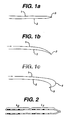
- Figure 1a shows an embodiment of guide wire structure as disclosed in US Patent 7288074 .
- Figure 1b shows the structure of Figure 1a when one of its guide wires is advanced rightwardly and the other is held steady;
- Figure 1c shows the structure of Figure 1a after further righthand advance of one of the guide wires
- Figure 2 shows an example of a pattern of markings which may be provided on the guide wires to indicate their relative position to a physician;
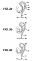
- Figure 3a to 3c show a guide wire structure advancing into the colon
- Figure 4 shows diagrammatically a handle for use in controlling movement of guide wires
- Figures 5a and 5b show successive stages in the use of a guide wire structure in conjunction with a bias tube
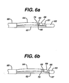
- Figures 6a and 6b show successive stages in the use of a cutting catheter to sever the junction between two guide wires
- Figure 7 shows two guide wire structures arranged in parallel
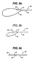
- FIGS. 8a to 8c illustrate diagrammatically the use of a guide wire structure which has a pivotal junction portion
- Figure 9 shows another guide wire structure described in US Parent 7288074 .
- Figure 10 illustrates an embodiment of the present invention in which a guidewire cross section is varied along its length to have a reduced cross section at a location spaced from the ends of the wire, such as at or close to the midpoint of length of the guide wire.
- Figure 11 shows the guide wire of Figure 10 bent into a generally U-shaped configuration for passage into a lumen such as the GI tract.
- Figures 12a, b, and c show alternative embodiments in which different cross-sections are employed.
- Figure 13 illustrates an embodiment of the guide wire of the present invention being advanced from the distal end of a medical device to form a loop forward of the distal end of the medical device.
- Figures 1-9 illustrate guide wire structures disclosed in US Patent 7288074 .
- Figures 10-13 illustrate a guide wire structure according to the present invention.
- the structure of Figure 1a comprises a first guide wire 1 and a second guide wire 2, the wires 1 and 2 being connected to one another by a junction 3 formed at the leading ends of the wires 1 and 2.
- the junction 3 is shown as being at the leading ends, it could alternatively be adjacent the leading ends.
- the length of the junction need be no more than is necessary to hold the leading ends securely together side by side. Depending on the nature of the junction, a length of as little as 5-10 mm may be sufficient, though a greater length may sometimes be preferable.
- the guide wires 2 and 3 can be made of the materials conventionally used for guide wires, for example straight stainless steel wire, coiled stainless steel wire, glass fiber, a plastics material, or nitinol.
- a guide wire has a floppy tip, i.e. a leading end portion, typically 4-5 cm in length, of greater flexibility than the remainder of the guide wire, in order to reduce the risk of the leading end of the guide wire causing damage to the wall of the lumen through which it is passing.
- two such conventional guide wires are joined together to produce the guide wire structure of Figure 1 , it can be these floppy tips, or parts thereof, which are joined together.
- the length of the junction can be less than the length of the floppy tips, so that some length of floppy material remains which is unaffected by the junction.
- each of the guide wires may be coated to reduce its coefficient of friction, as is done with conventional guide wires.
- guide wires can be coated with a low friction material such as silicone, or with a hydrophilic material which becomes slippery in use in a patient, or with both a low friction material such as silicone and hydrophilic material applied over the low friction material.
- the junction 3 can be formed in any desired manner, provided the resulting leading end of the guide wire structure is not such as to damage the wall of the GI tract or other body lumen, nor cause undue pain when in contact therewith.
- the junction can be made by gluing or welding the leading end portions together and then covering those portions with heat shrink tubing.
- the end portions could be held together by having a metal band crimped on to them, optionally enclosed by a cover made of a softer material.
- guide wires it is not essential for all the guide wires, or both the guide wires, as the case may be, to be of material which would normally be regarded as guide wire material.
- one of the guide wires may be made of a thread, which is joined to the other guide wire by being tied to it.
- a guide wire structure having an even number n of guide wires greater than two could be formed by folding half that number of guide wires.
- Figure 1b shows the result of advancing the guide wire 1 rightwardly, as indicated by the arrow, whilst holding the guide wire 2 still. As indicated in Figure 1b , this causes the distal region of the guide wire structure to curve in a direction so that the advanced guide wire 1 is on the outside of the curve and the still guide wire 2 is on the inside of the curve.
- Figure 1c shows the loop in an end region of guide wire 1. This is illustrated in Figure 1c , where the loop is denoted by reference numeral 4.
- the guide wires can be received, at their ends remote from the junction 3, in a handle which can be moved up and down the guide wires as they are advanced and retracted.
- the handle should allow precise regulation of the relative lengths of the two guide wires. It should also allow the introduction of the various catheters, imagers and other accessories, discussed in more detail below, giving accurate information on their relationship to the junction 3.
- the handle may be provided with a reversible motor drive which enables both guide wires to be driven.
- the motor drive itself may provide data to enable the user to monitor the lengths of the guide wires which have been fed forward.
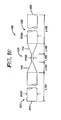
- the illustrated handle 40 comprises a pistol grip 41 within which is mounted a pair of electric motors 42 (of which one is shown) powered either by a battery 43 or a mains supply 44.
- the motors are controlled by respective finger controls 45, one for each motor, each control having forward, reverse and stop positions.
- Each motor provides drive, via a respective gear, shown diagrammatically at 46, to a respective belt or chain drive 47, each of which propels a respective guide wire 48 forwardly (or backwardly).
- a switch 47a is provided to cause the driving belts or chains to move away from the wires, to allow the wires to be released, for example at the conclusion of a procedure.
- a lock mechanism 49 is provided to attach the handle 40 to a catheter or to an accepting channel of an endoscope, through which the guide wire is to be driven.
- the guide wires are stored in a coiled plastics tube 50, either with both wires side by side in a single tube or each in its own tube. This has the benefit of keeping the guide wires clean, and avoiding the risk of their trailing on to the floor. Under some conditions this storage facility may be omitted.
- the presence of a loop at the leading end of the structure rather than the tip of a single wire makes the structure more likely to follow the main course of the lumen, and less likely to inadvertently enter branches off it.
- the loop is not permanently present, and can be eliminated by putting the structure into the configuration shown in Figure 1a , means that the structure can easily, and without damage to itself, be passed along a very narrow passageway. It can therefore be passed, for example, along a channel of an endoscope or down a catheter, as is described further below.
- the guide wire structure when the guide wire structure is not in an endoscope or catheter, but is advancing directly along a patient lumen, it is not always desirable to do so with a loop at the front (for example if it has to pass through a small opening). Under such circumstances the guide wire structure is allowed to revert to the straight form shown in Figure 1a with both guidewires being advanced aligned and in unison.
- FIGS. 3a to 3c show diagrammatically, and by way of example, successive stages in advancing the guide wire structure along a colon 30. It is shown being introduced in conjunction with a catheter 31 within which the whole guide wire structure is slidably received.
- the individual guide wires are denoted as W 1 and w 2 . Advancement takes place by alternately:
- the guide wires are preferably each provided with a pattern of markings, distributed along their length, to indicate how far each individual guide wire has been inserted.
- a pattern of markings in a given colour, and similar in nature to a bar code is spaced along a first length (L 1 ), and then repeated along successive lengths (of which only L 2 is shown) each time in a different colour.
- L 1 first length
- L 2 successive lengths
- the guide wire structure can be provided with other forms of position indication. It is known to provide a conventional guide wire with a series of miniature electrically conductive coils which surrounded the guide wire and are spaced along its length, the coils being connected to a source of electrical current, whereby each coil becomes a miniature electromagnet. Such coils can be provided on the guide wires used to form the guide wire structure shown. A sensing device outside the patient is used to detect the position of the coils within the patient, and thereby determine the location of the guide wires.
- the path of the guide wire structure can be influenced by the use of a catheter, which can be passed over one or both of the two guide wires, when there are precisely two, or over one, some, or all of the guide wires, when there are more than two.
- the catheter has a curved tip, which allows the application of torque to bias the forward motion of the guide wire (or wires) over which it passes in any given direction.
- Figures 5a and 5b show a pair of guide wires 51 and 52 joined at a junction 53.
- Guide wire 51 is received within a catheter 54, referred to herein as a bias tube, the leading end portion of which is so formed as to have a curvature in it.
- the guide wire 51 with the bias tube, and the guide wire 52 are both received within an outer catheter 55.
- the ends of the catheters 51 and 52 remote from their tips emerge from the catheter 55 to allow them to selectively advance and retract.
- the end of the bias tube 54 remote from the curved end thereof emerges from the outer catheter 55 at the user's end.
- the bias tube helps to ensure that the combined guide wire structure curves in the desired direction. If it were desired to cause the structure to advance in some other direction, this could be achieved by twisting the catheter 55 about its longitudinal axis, thus altering the positions of the guide wires relative to the lumen in which they are being advanced.
- the purpose of the guide wire is, as its name indicates, to act as a guide for some other element. Accordingly, when the guide wire structure is in place some other element is then passed over it, or otherwise pushed or advanced along the guide wire.
- a catheter introduced subsequently can pass over one or both of the guide wires, when there are precisely two, or over one, some, or all of the guide wires, when there are more than two.
- the catheter is passed over both, or all, the guide wires, as the case may be, the leading end of the catheter will be free to pass beyond the leading end of the guide wire structure once it reaches that point. If the catheter is not passed over both, or all, the guide wires, for example if it is passed over only one of two interconnected guide wires, the leading end of the catheter will normally be unable to pass beyond the connection between the guide wires.
- Figures 6a and 6b show guide wires 61 and 62 connected by a junction 63 and extending within an outer catheter 65.
- a cutting catheter 64 surrounds one of the guide wires, in this case the guide wire 61.
- the catheter 64 has a cutting tip (not visible in Figure 6a ) which, when the catheter 64 is advanced over the guide wire 61, severs the junction 63.
- Figure 6b shows the severing operation partly completed.
- the cutting catheter comprises a cylindrical cutting member 66 with a circular cutting edge 67 (visible in Figure 6b but not in Figure 6a ) formed at its leading end.
- a cylindrical sheath 68 which is biased to a forward protecting position by a compression spring 69 located between the rearward end of the sheath 68 and a stop 70 fixed to the end of the catheter.
- the cutting edge 67 emerges from the sheath 68 and severs the junction 63.
- the spring automatically causes the sheath 68 to move forwards, covering the cutting edge 67 and preventing it from harming the patient.
- FIG. 7 An example of such an embodiment is shown in Figure 7 .
- This comprises two parallel catheters 72a and 72b, which are preferably connected together side by side in such a way as to allow each to move longitudinally with respect to the other.
- the connection is provided by a T-shaped stud 73 formed on catheter 72a which is slidable in a correspondingly shaped passageway 74 formed in catheter 72b and running longitudinally along it.
- a single stud may be provided, or a plurality of studs spaced along the length of catheter 72a, or there may be a continuous stud running along all or part of the length of catheter 72a.
- Catheter 72a receives a first guide wire structure 75a, comprising a pair of wires W 1 and W 2 joined at a junction 76a.
- Catheter 72b receives a guide wire structure 75b, comprising a pair of wires W 3 and W 4 joined at a junction 76b.
- a similar cycle of steps can be achieved by a modified form of the embodiment of Figure 7 , in which one or each of the two catheters 72a and 72b is replaced by a suction catheter.
- a suction catheter can be used to effect the above described straightening of the gut by pulling back on it while suction is being applied. The suction is only applied during the straightening step.
- Yet another modification is to replace one of the guide wire structures by a soft balloon, which can be inflated to engage the gut wall, and then pulled back to straighten the gut.
- a small imager (for example a CCD or CMOS chip) on a catheter could be passed along the guide wire or guide wires to the tip. This could optionally be propelled along the guide wire by a water jet or some other means of tip propulsion to reduce the force that has to be exerted outside the patient.
- a source of white or coloured light could be also introduced by the same means. This source could be in the form of light emitting diodes or could use fibre-optics.
- One of the wires could be optionally formed out of a fiberoptic bundle. It would be easier to take the optical signal through a light-weight insulated wire which could be incorporated into the guide wire or via a separate wire in a catheter.
- the imager could then convert the optical information to radiowaves or microwaves, to send the information to an aerial attached to, or adjacent to, the exterior of the patient.
- a separate soft catheter could be run over the guide wire to the tip and this could be used to introduce air from a controlled pump to inflate the viscus. Water for rinsing purposes could be passed through this catheter or through some other from a water pump.
- a catheter could be passed over one of the guide wires, which would provide a channel through which biopsies could be performed. This is preferably done after the imager referred to in (a) above has been placed in position, so that the imager can be used to view the biopsy procedure.
- This catheter might have tip angulation properties.
- a double lumen catheter could be passed over the double wire, which might allow the introduction of another wire of greater stiffness or with a curled tip to allow the movement of the device in a desired direction.
- an overtube could be passed, for example to the cecum.
- the guide wire and the imager could then be withdrawn and a conventional endoscope could be passed through the overtube to deliver therapy, for example removing a polyp or cancer.
- a conventional endoscope could be introduced into a body lumen by passing it over the guide wire structure.
- a conventional endoscope may be too stiff for this to be possible, and the guide wire structure offers the possibility of, in effect, constructing an endoscope within a patient.
- a number of catheters, each providing one or more of the utilities normally provided a conventional endoscope are successively passed over one or more of the guide wires, so that result is an assemblage of these various elements within the patient.
- a particular advantage of proceeding in this way is that the force required to advance each of the individual catheters is substantially less than that required to advance a complete conventional endoscope (e.g. a colonoscope or an enteroscope), since the latter is much stiffer and has much greater mass.
- the endoscope can have those facilities which are required for the particular patient, and, only those facilities, so that the endoscope is tailored to the requirements of the medical procedure being carried out.
- the guide wire structure should preferably comprise more than two guide wires, for example three or four guide wires.
- a structure having more than two guide wires is particularly useful for the purpose discussed above of assembling an endoscope in situ, it may also have value in relation to the procedure for introducing the guide wire structure into a lumen.
- the two-guide wire structure shown in Figures 1a to 1c allows curvature in only one plane, so that steering the structure in three dimensions requires the user to twist the structure about its longitudinal axis, for example by using a catheter to which the necessary torque can be applied.
- more than two guide wires are provided it is possible to curve the structure in any plane; three guide wires are sufficient for this purpose.
- Figures 8a to 8c illustrate the use of a guide wire structure 80 which comprises two guide wires 81 and 82 connected by a junction portion 83.
- the junction portion 83 is pivotal about an axis located at the proximal end of the portion 83, so that, as shown in Figure 8a , it can pivot to such an extent that it lies flat along the distal end portion of guide wire 81.
- This is advantageous in that it makes possible, or makes easier, movement of the portion 83 within a catheter 84, not only where there is no loop present (as in Figure 8c ) but also when there is (as shown in Figure 8a ).
- the diameter of the catheter 84 would actually be substantially greater than that shown in these Figures. It is also to be understood that instead of being joined by a junction portion 83 of significant length, as illustrated, the guide wires could alternatively be joined by a junction of substantially no length, i.e. the ends of the guide wires could be connected by a junction consisting, at least in substance of just a pivot point.
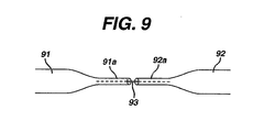
- Figure 9 shows yet another guide wire structure in which a similar pivoting action can be achieved.
- This comprises guide wires 91 and 92, having respective floppy tip portions 91a and 92a connected to one another by a thread or highly flexible wire 93.
- This thread or wire can be inserted into the portions 91a and 92a, or attached to their surfaces.
- FIGS 10-13 illustrate a guide wire structure according to the present invention.
- the guide wire structure includes a continuous, unitary wire having a segment (which can be positioned generally in the middle portion of the wire), which segment has a bending moment of inertia which is lower than the bending moment of inertia of the adjacent wire segments.
- the wire can change in cross sectional shape or dimension at a location that is not a terminal end, so as to provide a bending hinge.
- the bending moment of inertia for a circular cross-section can be calculated as ⁇ r 4 /4, where r is the radius of the cross-section.
- the bending moment of inertia for a rectangular cross-section can be calculated as bh 3 /12, where b is the base of the rectangle and h is the height.
- Figure 10 shows an embodiment of guide wire structure of the present invention comprising a continuous, unitary wire 100 that has varying cross sectional area along a portion of its length.
- the wire 100 can have a first segment 121 having a generally circular cross section of nominal diameter D101 and a length L101, a second segment 122 having a generally circular cross-section of nominal diameter D102 and a length L102, and a third segment 123 having a generally circular cross-section of nominal diameter D103 and length L103.
- the wire 100 can also include a tapered transition segment 110 having a conical shape and a length L104 and extending between segment 121 and segment 123, and a tapered transition segment 112 having a length L105 and extending between segment 123 and segment 122.
- the reduced diameter D103 of the third segment 123 relative to the diameter D101 and the diameter D102 provides the third segment 123 with a bending moment of inertia which is lower than that of the segments 121 and 122. Accordingly, the wire 100 can bend at the third segment 123 to provide a hinge, which hinge can encompass the length L103 of third segment 123; as well as some or all of the lengths L104 and L105 of segments 110 and 112. In one embodiment, the hinge so formed can be an elastic hinge.
- the wire 100 with it's associated hinge can be used in the embodiment as described below, as well as in those methods disclosed with reference to Figures 1-9 above, without the need for attaching or otherwise joining two wires or using different materials.
- the diameters D101 and D102 can be between 0.25 mm (0.010 inch) to 0.89 mm (0.035 inch), and more particularly 0.41 mm (0.016 inch) to 0.51 mm (0.020 inch).
- the third segment 123 can have a diameter D103 of between 0.13 mm (0.005 inch) and 0.25 mm (0.010 inch), and in one embodiment D103 can be about 0.18 mm (0.007 inch).
- Each of L101 and L102 can be at least about 0.9 m (3 feet), and can be between 1.8 m (6 feet) and 3.7m (12 feet).
- the combined length lengths L101, L102, L103, L104, and L105 can be between 2.1 m (7 feet) and 7.6 m (25 feet). In one embodiment, the lengths L101 and L102 can be about equal, and their combined length can be at least about 6.1 m (20 feet).
- Length L103 of the third segment can be between 2.64 mm (0.100 inch) to 12.7 mm (0.500 inch), and in one embodiment can be about 7.62 mm (0.300 inch).
- the reduced cross-section of the third segment 123 can be formed by centerless grinding.
- a reduced cross-section can be formed using a grinding machine such as a TF-9CPG System 2000 Guide Wire Profile Grinder available from Glebar Company of Franklin Lakes, NJ.
- the wire 100 can be enclosed in one or more low friction and/or lubricous sleeves.
- the first wire segment 121 is enclosed in a sleeve 155
- second wire segment 122 is enclosed in a sleeve 159
- the third segment and the transition segments are enclosed in a sleeve 157.
- the sleeves 155, 157, and 159 can be formed of a low friction material, such as PTFE or polyester.
- Indicators are associated with the first and second wire segments 121 and 122 so that the wire segments can be distinguished when viewed through a camera or other optical device associated with an endoscope or other medical device. For instance, the indicators can be,visual, and can employ different colors.
- the sleeves 155 and 159 can be provided in different colors and/or with different patterns of markings.
- sleeve 155 has a pattern of heavy, diagonally slanted marks, while sleeve 159 has a pattern of lighter, non-slanted markings.
- the marking colors and/or the background color of the sleeves can be different to distinguish sleeve 155 from sleeve 159. Alternating stripes of different colors can also be used to distinguish sleeve 155 from sleeve 159, and thus segment 121 from 122 as viewed through a visualization device.
- Sleeve 157 can have yet another color or pattern of colors to provide a visual indication of the location of the third segment 123.
- Figure 11 illustrates the wire 100 bent at the third segment 123 to form a narrow wire loop for introduction into a body cavity.
- the wire 100 is illustrated with a generally U-shaped bend 150 with a radius R110 so that the wire does not kink upon placement through a colonoscope working channel, does not form a sharp point that can damage tissue upon placement in a body lumen, and preferably does not substantially plastically deform.
- the radius R110 can be about 0.75mm to about 1.5mm, and more particularly about 1mm.
- Suitable biocompatible materials from which such a wire can be constructed include those mentioned from which the wires of Figures 1-9 can be formed, including without limitation a superelastic material such as nitinol. Other materials, such as steel and alloys can also be used.
- a superelastic material such as nitinol.
- Other materials such as steel and alloys can also be used.
- Nitinol NDC SE508 available from Nitinol Devices and Components, a Johnson & Johnson Company of Fremont, CA.
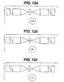
- Figure 12 illustrates alternative embodiments in which the cross-section of the narrowed length 103 is not round.
- Different cross sectional shapes may be formed, such as changing a round wire to a flat rectangular cross section in Figure 12a , an oval cross section in Figure 12b , or a square cross section in Figure 12c .
- Other cross-sectional shapes such as triangular, hexangonal, or other polygonal shapes may be employed.
- Preferential bending planes of certain cross sectional shapes can be used for the purposes of directing the U-loop of the wire. For instance, a rectangular, oval, or triangular cross-section can be employed to direct bending about a particular axis.
- the guide wire structure with wire 100 of the present invention can be used in place of the wire configurations shown in Figures 1-9 , as well as with the device illustrated in US Patent US 2004/111020 A1 .
- Figure 13 is a schematic illustration of the guide wire structure with wire 100 in use with a medical device 300.
- medical device 300 can be a flexible endoscope, such as a flexible colonosocope, or a device such as is shown in the above referenced patent application.
- Medical device 300 can include a handle 310, which is positioned outside a patient, an elongate flexible body portion 330, and a distal end 320 which can be positioned in a patient, such as in a patient's GI tract, with distal end 320 sized and shaped to be advanced in the GI tract.
- the medical device can also include a working channel 350 extending through the body portion 330 and opening at the distal end 320 of the device 300, a camera 360, light source 370, a camera lens wash nozzle/irrigation nozzle 380, a light source 392, and a light source 394. Suction can be provided through working channel 350, if desired.
- the guide wire with wire 100 of the present invention can be positioned within the working channel 350 such that the U shaped bend in third segment 123 is positioned in the patient's body, and the ends of the guide wire extend through an access opening of the handle 310.
- the ends of the guide wire are indicated by numeral 221 (associated with first segment 121) and numeral 222 (associated with second segment 122).
- the guide wire with wire 100 can be used generally as shown in Figures 3A-3C to advance a device into a body lumen, such as the GI tract.
- a body lumen such as the GI tract.
- the first segment 121 is advanced through the working channel relative to second segment 122, so that the first segment 121 takes on a curvature having a radius of curvature greater than Radius of curvature R110, as shown in Figure 13 .
- end 222 can then be held fixed, and end 221 can be advanced distally toward handle 310 so that additional length of the first segment 121 is advanced distally out of working channel 350, thereby advancing the relatively large radius of curvature loop distally in the GI tract.
- end 221 can be pulled in tension (proximally) while simultaneously pushing (distally) the elongate body portion 330 distally along wire segments 121 and 122 in working channel 350, so that the distal end 350 moves forward (distally) into the GI tract.
- the wire segments 121 and 122 serve as a track upon which the distal end 350 of device 300 can be advanced.
Landscapes
- Health & Medical Sciences (AREA)
- Life Sciences & Earth Sciences (AREA)
- Biophysics (AREA)
- Pulmonology (AREA)
- Engineering & Computer Science (AREA)
- Anesthesiology (AREA)
- Biomedical Technology (AREA)
- Heart & Thoracic Surgery (AREA)
- Hematology (AREA)
- Animal Behavior & Ethology (AREA)
- General Health & Medical Sciences (AREA)
- Public Health (AREA)
- Veterinary Medicine (AREA)
- Media Introduction/Drainage Providing Device (AREA)
Claims (14)
- Führungsdrahtstruktur zum Einführen in einen Innenraum, der durch eine Wand definiert ist, wobei der Führungsdraht einen durchgängigen einheitlichen Draht (100) umfasst mit einem ersten Segment (121), einem zweiten Segment (122) und einem dritten Segment (123), welches zwischen dem ersten und dem zweiten Segment angeordnet ist, wobei das dritte Segment ein Biegeträgheitsmoment aufweist, das kleiner als ein Biegeträgheitsmoment des ersten Segments und kleiner als ein Biegeträgheitsmoments des zweiten Segments ist, gekennzeichnet durch eine erste Hülse (155), welche das erste Segment umgibt, und eine zweite Hülse (159), welche das zweite Segment umgibt, wobei die erste und zweite Hülse visuell unterscheidbar sind.
- Führungsdrahtstruktur nach Anspruch 1, wobei das dritte Segment (123) eine Querschnittsfläche aufweist, die kleiner ist als die Querschnittsflächen des ersten Segments (121) und des zweiten Segments (122).
- Führungsdrahtstruktur nach Anspruch 1, wobei das erste, zweite und/oder dritte Segment (121, 122, 123) kreisförmige Querschnitte aufweisen.
- Führungsdrahtstruktur nach Anspruch 1, wobei das erste, zweite und/oder dritte Segment (121, 122, 123) nicht kreisförmige Querschnitte aufweisen.
- Führungsdrahtstruktur nach Anspruch 1, wobei der Draht aus Nitinol gebildet ist.
- Führungsdrahtstruktur nach Anspruch 1, wobei die zusammengefasste Länge des ersten Segments, des zweiten Segments und des dritten Segments wenigstens 2,1 m (7 ft.) beträgt.
- Führungsdrahtstruktur nach Anspruch 1, wobei die zusammengefasste Länge des ersten Segments, des zweiten Segments und des dritten Segments zwischen 2,1 m (7 ft.) und 7,6 m (25 ft.) beträgt.
- Führungsdrahtstruktur nach Anspruch 1, wobei die zusammengefasste Länge des ersten Segments, des zweiten Segments und des dritten Segments wenigstens 6,1 m (20 ft.) beträgt.
- Führungsdrahtstruktur nach Anspruch 1, wobei das erste Segment eine Länge von wenigstens 1,8 m (6 ft.) aufweist und einen allgemein kreisförmigen Querschnitt mit einem Durchmesser zwischen 0,28 mm (0,011 Zoll) und 0,89 mm (0,035 Zoll) aufweist.
- Führungsdrahtstruktur nach Anspruch 9, wobei das dritte Segment einen Durchmesser zwischen 0,13 mm (0,005 Zoll) und 0,25 mm (0,010 Zoll) aufweist.
- Führungsdrahtstruktur nach Anspruch 1, wobei das erste Segment (121) eine Länge von wenigstens 1,8 m (6 ft.) beträgt und wobei das erste Segment einen maximalen Querschnittsdurchmesser von nicht mehr als 0,89 mm (0,035 Zoll) aufweist und wobei das dritte Segment (123) einen maximalen Querschnittsdurchmesser von nicht mehr als 0,25 mm (0,010 Zoll) aufweist.
- Führungsdrahtstruktur nach Anspruch 1, wobei das dritte Segment (123) gebogen ist.
- Führungsdrahtstruktur nach Anspruch 1, wobei das dritte Segment (123) ein elastisches Gelenk zur Verfügung stellt.
- Führungsdrahtstruktur nach einem der vorhergehenden Ansprüche, wobei das erste Segment (121) einen im Wesentlichen konstanten Durchmesser aufweist; das zweite Segment (122) einen im Wesentlichen konstanten Durchmesser aufweist; und weiterhin Folgendes umfasst:ein sich verjüngendes Segment (110) mit abnehmenden Durchmesser, das sich von dem ersten Segment zu dem dritten Segment erstreckt; undein sich verjüngendes Segment (112) mit abnehmendem Durchmesser, das sich von dem zweiten Segment zu dem dritten Segment erstreckt.
Applications Claiming Priority (5)
| Application Number | Priority Date | Filing Date | Title |
|---|---|---|---|
| GBGB0307715.3A GB0307715D0 (en) | 2003-04-03 | 2003-04-03 | Guide wire structure for insertion into an internal space |
| US10/406,020 US7351202B2 (en) | 2002-12-05 | 2003-04-03 | Medical device with track and method of use |
| US10/409,270 US7288074B2 (en) | 2003-04-03 | 2003-04-08 | Guide wire structure for insertion into an internal space |
| US10/729,754 US20040199088A1 (en) | 2003-04-03 | 2003-12-05 | Guide wire having bending segment |
| PCT/US2004/009966 WO2004089455A2 (en) | 2003-04-03 | 2004-04-01 | Guide wire having bending segment |
Publications (2)
| Publication Number | Publication Date |
|---|---|
| EP1620157A2 EP1620157A2 (de) | 2006-02-01 |
| EP1620157B1 true EP1620157B1 (de) | 2011-11-16 |
Family
ID=33163054
Family Applications (1)
| Application Number | Title | Priority Date | Filing Date |
|---|---|---|---|
| EP04749610A Expired - Lifetime EP1620157B1 (de) | 2003-04-03 | 2004-04-01 | Führungsdraht mit einem biegesegment |
Country Status (5)
| Country | Link |
|---|---|
| EP (1) | EP1620157B1 (de) |
| JP (1) | JP4650901B2 (de) |
| AU (1) | AU2004227920B2 (de) |
| CA (1) | CA2522198C (de) |
| WO (1) | WO2004089455A2 (de) |
Families Citing this family (4)
| Publication number | Priority date | Publication date | Assignee | Title |
|---|---|---|---|---|
| CA2673557C (en) * | 2006-12-22 | 2013-02-12 | Wilson-Cook Medical Inc. | Splittable wire guide |
| IT1391568B1 (it) * | 2008-09-05 | 2012-01-11 | E V R Endovascular Res Es S A | Cavo guida di navigazione attraverso una anatomia con condotti ramificati |
| US9629653B2 (en) | 2013-11-01 | 2017-04-25 | Cook Medical Technologies Llc | Looped wire catheter and method |
| JPWO2017203582A1 (ja) | 2016-05-23 | 2019-04-11 | オリンパス株式会社 | 内視鏡用デバイスおよび内視鏡システム |
Family Cites Families (16)
| Publication number | Priority date | Publication date | Assignee | Title |
|---|---|---|---|---|
| US5203772A (en) * | 1989-01-09 | 1993-04-20 | Pilot Cardiovascular Systems, Inc. | Steerable medical device |
| US5113872A (en) * | 1990-04-18 | 1992-05-19 | Cordis Corporation | Guidewire extension system with connectors |
| US5389073A (en) * | 1992-12-01 | 1995-02-14 | Cardiac Pathways Corporation | Steerable catheter with adjustable bend location |
| ES2089775T3 (es) * | 1993-05-19 | 1996-10-01 | Schneider Europ Ag | Alambre de guia. |
| US5363847A (en) * | 1993-10-27 | 1994-11-15 | Cordis Corporation | Guidewire having double distal portions |
| JP3460849B2 (ja) * | 1994-01-31 | 2003-10-27 | 日本ゼオン株式会社 | 医療器具 |
| DK175166B1 (da) * | 1995-01-03 | 2004-06-21 | Cook William Europ | Fremgangsmåde til fremstilling af et aggregat til placering af en embolisationscoil i det vaskulære system og et sådant aggregat samt et apparat til fremføring af aggregatet |
| US5664580A (en) * | 1995-01-31 | 1997-09-09 | Microvena Corporation | Guidewire having bimetallic coil |
| US5807279A (en) * | 1996-09-27 | 1998-09-15 | Cordis Corporation | Guidewire having radiopaque distal tip |
| US6106488A (en) * | 1998-08-11 | 2000-08-22 | Scimed Life Systems, Inc. | Flexural rigidity profile guidewire tip |
| WO2000065987A1 (en) * | 1999-04-30 | 2000-11-09 | Applied Medical Resources Corporation | Guidewire |
| US7306618B2 (en) * | 1999-07-30 | 2007-12-11 | Incept Llc | Vascular device for emboli and thrombi removal and methods of use |
| US6290656B1 (en) * | 1999-12-30 | 2001-09-18 | Advanced Cardiovascular Systems, Inc. | Guide wire with damped force vibration mechanism |
| JP2001327606A (ja) * | 2000-05-23 | 2001-11-27 | Japan Lifeline Co Ltd | 医療用挿通線体 |
| DE10192161T1 (de) * | 2000-05-30 | 2002-09-05 | Olympus Optical Co | Medizinischer Führungsdraht |
| WO2004089456A1 (en) * | 2003-04-03 | 2004-10-21 | Ethicon Endo-Surgery, Inc. | Guide wire structure for insertion into an internal space |
-
2004
- 2004-04-01 EP EP04749610A patent/EP1620157B1/de not_active Expired - Lifetime
- 2004-04-01 WO PCT/US2004/009966 patent/WO2004089455A2/en not_active Ceased
- 2004-04-01 JP JP2006509555A patent/JP4650901B2/ja not_active Expired - Fee Related
- 2004-04-01 CA CA2522198A patent/CA2522198C/en not_active Expired - Fee Related
- 2004-04-01 AU AU2004227920A patent/AU2004227920B2/en not_active Ceased
Also Published As
| Publication number | Publication date |
|---|---|
| EP1620157A2 (de) | 2006-02-01 |
| JP2006521893A (ja) | 2006-09-28 |
| JP4650901B2 (ja) | 2011-03-16 |
| CA2522198A1 (en) | 2004-10-21 |
| AU2004227920A1 (en) | 2004-10-21 |
| WO2004089455A2 (en) | 2004-10-21 |
| AU2004227920B2 (en) | 2011-03-24 |
| WO2004089455A3 (en) | 2004-12-02 |
| CA2522198C (en) | 2012-05-22 |
Similar Documents
| Publication | Publication Date | Title |
|---|---|---|
| US20040199088A1 (en) | Guide wire having bending segment | |
| US7128708B2 (en) | Shape lockable apparatus and method for advancing an instrument through unsupported anatomy | |
| CN108882834B (zh) | 柔性内窥镜支撑系统 | |
| US7041052B2 (en) | Shape lockable apparatus and method for advancing an instrument through unsupported anatomy | |
| EP2368508B1 (de) | Endoskopisches drehbares Elektrischmesser | |
| CN101061942B (zh) | 医疗套管及医疗套管系统 | |
| US20050137454A1 (en) | Shape lockable apparatus and method for advancing an instrument through unsupported anatomy | |
| CN105828690A (zh) | 内窥镜 | |
| JP2007301360A (ja) | 処置具挿脱用補助装置 | |
| CN1859941B (zh) | 具有弯曲段的导丝 | |
| EP1608424B1 (de) | Führungsdrahtstruktur zur einführung in einen innenraum | |
| EP1620157B1 (de) | Führungsdraht mit einem biegesegment | |
| JP2025533673A (ja) | 医用装置の挿管のためのシステムおよび方法 | |
| JPH07250808A (ja) | 内視鏡 | |
| CN118401161A (zh) | 用于可配置内窥镜弯曲段的系统和方法 |
Legal Events
| Date | Code | Title | Description |
|---|---|---|---|
| PUAI | Public reference made under article 153(3) epc to a published international application that has entered the european phase |
Free format text: ORIGINAL CODE: 0009012 |
|
| 17P | Request for examination filed |
Effective date: 20051129 |
|
| AK | Designated contracting states |
Kind code of ref document: A2 Designated state(s): DE ES FR GB IT NL |
|
| R17P | Request for examination filed (corrected) |
Effective date: 20051012 |
|
| DAX | Request for extension of the european patent (deleted) | ||
| RBV | Designated contracting states (corrected) |
Designated state(s): DE ES FR GB IT NL |
|
| RAP1 | Party data changed (applicant data changed or rights of an application transferred) |
Owner name: ETHICON ENDO-SURGERY, INC. Owner name: UCL BIOMEDICA PLC |
|
| RIN1 | Information on inventor provided before grant (corrected) |
Inventor name: LONG, GARY, L. Inventor name: TIERNEY, SCOTT, J. Inventor name: SWAIN, CHRISTOPHER, PAUL Inventor name: GEE, KEVIN, K. Inventor name: BAKOS, GREGORY, J. |
|
| RAP1 | Party data changed (applicant data changed or rights of an application transferred) |
Owner name: ETHICON ENDO-SURGERY, INC. Owner name: UCL BUSINESS PLC |
|
| 17Q | First examination report despatched |
Effective date: 20090703 |
|
| GRAP | Despatch of communication of intention to grant a patent |
Free format text: ORIGINAL CODE: EPIDOSNIGR1 |
|
| GRAS | Grant fee paid |
Free format text: ORIGINAL CODE: EPIDOSNIGR3 |
|
| GRAA | (expected) grant |
Free format text: ORIGINAL CODE: 0009210 |
|
| RAP1 | Party data changed (applicant data changed or rights of an application transferred) |
Owner name: UCL BUSINESS PLC Owner name: ETHICON ENDO-SURGERY, INC. |
|
| AK | Designated contracting states |
Kind code of ref document: B1 Designated state(s): DE ES FR GB IT NL |
|
| REG | Reference to a national code |
Ref country code: GB Ref legal event code: FG4D |
|
| REG | Reference to a national code |
Ref country code: DE Ref legal event code: R096 Ref document number: 602004035327 Country of ref document: DE Effective date: 20120112 |
|
| REG | Reference to a national code |
Ref country code: ES Ref legal event code: FG2A Ref document number: 2374398 Country of ref document: ES Kind code of ref document: T3 Effective date: 20120216 |
|
| REG | Reference to a national code |
Ref country code: NL Ref legal event code: T3 |
|
| PLBE | No opposition filed within time limit |
Free format text: ORIGINAL CODE: 0009261 |
|
| STAA | Information on the status of an ep patent application or granted ep patent |
Free format text: STATUS: NO OPPOSITION FILED WITHIN TIME LIMIT |
|
| 26N | No opposition filed |
Effective date: 20120817 |
|
| REG | Reference to a national code |
Ref country code: DE Ref legal event code: R097 Ref document number: 602004035327 Country of ref document: DE Effective date: 20120817 |
|
| PGFP | Annual fee paid to national office [announced via postgrant information from national office to epo] |
Ref country code: NL Payment date: 20140410 Year of fee payment: 11 |
|
| REG | Reference to a national code |
Ref country code: NL Ref legal event code: MM Effective date: 20150501 |
|
| REG | Reference to a national code |
Ref country code: FR Ref legal event code: PLFP Year of fee payment: 13 |
|
| PG25 | Lapsed in a contracting state [announced via postgrant information from national office to epo] |
Ref country code: NL Free format text: LAPSE BECAUSE OF NON-PAYMENT OF DUE FEES Effective date: 20150501 |
|
| REG | Reference to a national code |
Ref country code: FR Ref legal event code: PLFP Year of fee payment: 14 |
|
| REG | Reference to a national code |
Ref country code: FR Ref legal event code: PLFP Year of fee payment: 15 |
|
| PGFP | Annual fee paid to national office [announced via postgrant information from national office to epo] |
Ref country code: PL Payment date: 20190426 Year of fee payment: 9 |
|
| REG | Reference to a national code |
Ref country code: ES Ref legal event code: FD2A Effective date: 20210826 |
|
| PGFP | Annual fee paid to national office [announced via postgrant information from national office to epo] |
Ref country code: GB Payment date: 20220303 Year of fee payment: 19 |
|
| PGFP | Annual fee paid to national office [announced via postgrant information from national office to epo] |
Ref country code: IT Payment date: 20220310 Year of fee payment: 19 Ref country code: FR Payment date: 20220308 Year of fee payment: 19 |
|
| PG25 | Lapsed in a contracting state [announced via postgrant information from national office to epo] |
Ref country code: ES Free format text: LAPSE BECAUSE OF NON-PAYMENT OF DUE FEES Effective date: 20200402 |
|
| PGFP | Annual fee paid to national office [announced via postgrant information from national office to epo] |
Ref country code: DE Payment date: 20220302 Year of fee payment: 19 |
|
| REG | Reference to a national code |
Ref country code: DE Ref legal event code: R119 Ref document number: 602004035327 Country of ref document: DE |
|
| GBPC | Gb: european patent ceased through non-payment of renewal fee |
Effective date: 20230401 |
|
| PG25 | Lapsed in a contracting state [announced via postgrant information from national office to epo] |
Ref country code: GB Free format text: LAPSE BECAUSE OF NON-PAYMENT OF DUE FEES Effective date: 20230401 |
|
| PG25 | Lapsed in a contracting state [announced via postgrant information from national office to epo] |
Ref country code: GB Free format text: LAPSE BECAUSE OF NON-PAYMENT OF DUE FEES Effective date: 20230401 Ref country code: FR Free format text: LAPSE BECAUSE OF NON-PAYMENT OF DUE FEES Effective date: 20230430 Ref country code: DE Free format text: LAPSE BECAUSE OF NON-PAYMENT OF DUE FEES Effective date: 20231103 |
|
| PG25 | Lapsed in a contracting state [announced via postgrant information from national office to epo] |
Ref country code: IT Free format text: LAPSE BECAUSE OF NON-PAYMENT OF DUE FEES Effective date: 20230401 |