EP1620276B1 - Configuration inversee d'axe de porte pour vehicule a faible garde au sol - Google Patents
Configuration inversee d'axe de porte pour vehicule a faible garde au sol Download PDFInfo
- Publication number
- EP1620276B1 EP1620276B1 EP03723088A EP03723088A EP1620276B1 EP 1620276 B1 EP1620276 B1 EP 1620276B1 EP 03723088 A EP03723088 A EP 03723088A EP 03723088 A EP03723088 A EP 03723088A EP 1620276 B1 EP1620276 B1 EP 1620276B1
- Authority
- EP
- European Patent Office
- Prior art keywords
- axle
- rotation
- housing
- assembly
- axis
- Prior art date
- Legal status (The legal status is an assumption and is not a legal conclusion. Google has not performed a legal analysis and makes no representation as to the accuracy of the status listed.)
- Expired - Lifetime
Links
- 230000009467 reduction Effects 0.000 claims description 29
- 239000000725 suspension Substances 0.000 description 5
- 230000000712 assembly Effects 0.000 description 3
- 238000000429 assembly Methods 0.000 description 3
- 230000008901 benefit Effects 0.000 description 3
- 238000012986 modification Methods 0.000 description 2
- 230000004048 modification Effects 0.000 description 2
- 238000004806 packaging method and process Methods 0.000 description 2
- 241001173939 Pseudoclanis axis Species 0.000 description 1
- 230000005540 biological transmission Effects 0.000 description 1
- 239000003638 chemical reducing agent Substances 0.000 description 1
- 238000010276 construction Methods 0.000 description 1
- 230000003467 diminishing effect Effects 0.000 description 1
Images

Classifications
-
- B—PERFORMING OPERATIONS; TRANSPORTING
- B60—VEHICLES IN GENERAL
- B60B—VEHICLE WHEELS; CASTORS; AXLES FOR WHEELS OR CASTORS; INCREASING WHEEL ADHESION
- B60B11/00—Units comprising multiple wheels arranged side by side; Wheels having more than one rim or capable of carrying more than one tyre
- B60B11/02—Units of separate wheels mounted for independent or coupled rotation
-
- B—PERFORMING OPERATIONS; TRANSPORTING
- B60—VEHICLES IN GENERAL
- B60B—VEHICLE WHEELS; CASTORS; AXLES FOR WHEELS OR CASTORS; INCREASING WHEEL ADHESION
- B60B35/00—Axle units; Parts thereof ; Arrangements for lubrication of axles
- B60B35/002—Axles of the low floor type, e.g. for low-floor city busses
-
- B—PERFORMING OPERATIONS; TRANSPORTING
- B60—VEHICLES IN GENERAL
- B60B—VEHICLE WHEELS; CASTORS; AXLES FOR WHEELS OR CASTORS; INCREASING WHEEL ADHESION
- B60B35/00—Axle units; Parts thereof ; Arrangements for lubrication of axles
- B60B35/12—Torque-transmitting axles
- B60B35/121—Power-transmission from drive shaft to hub
- B60B35/122—Power-transmission from drive shaft to hub using gearings
-
- B—PERFORMING OPERATIONS; TRANSPORTING
- B60—VEHICLES IN GENERAL
- B60B—VEHICLE WHEELS; CASTORS; AXLES FOR WHEELS OR CASTORS; INCREASING WHEEL ADHESION
- B60B35/00—Axle units; Parts thereof ; Arrangements for lubrication of axles
- B60B35/12—Torque-transmitting axles
- B60B35/16—Axle housings
- B60B35/163—Axle housings characterised by specific shape of the housing, e.g. adaptations to give space for other vehicle elements like chassis or exhaust system
-
- B—PERFORMING OPERATIONS; TRANSPORTING
- B60—VEHICLES IN GENERAL
- B60Y—INDEXING SCHEME RELATING TO ASPECTS CROSS-CUTTING VEHICLE TECHNOLOGY
- B60Y2200/00—Type of vehicle
- B60Y2200/10—Road Vehicles
- B60Y2200/14—Trucks; Load vehicles, Busses
- B60Y2200/143—Busses
- B60Y2200/1432—Low floor busses
-
- Y—GENERAL TAGGING OF NEW TECHNOLOGICAL DEVELOPMENTS; GENERAL TAGGING OF CROSS-SECTIONAL TECHNOLOGIES SPANNING OVER SEVERAL SECTIONS OF THE IPC; TECHNICAL SUBJECTS COVERED BY FORMER USPC CROSS-REFERENCE ART COLLECTIONS [XRACs] AND DIGESTS
- Y10—TECHNICAL SUBJECTS COVERED BY FORMER USPC
- Y10S—TECHNICAL SUBJECTS COVERED BY FORMER USPC CROSS-REFERENCE ART COLLECTIONS [XRACs] AND DIGESTS
- Y10S180/00—Motor vehicles
- Y10S180/905—Axles
Definitions
- the present invention relates to an inverted portal axle configuration which provides for a vehicle having a low floor.
- Mass transit vehicles such as trolley cars, buses, and the like typically have seats aligned at the lateral sides of the vehicle, with a central aisle and floor extending along the vehicle.
- the vehicle floor and aisle positioned relatively low to the ground. This provides faster cycle time at bus stops.
- Many such vehicles provide a rigid axle having a gear box at each longitudinal end to form an inverted portal axle configuration.
- the inverted portal axle configuration is particularly effective in providing a low floor vehicle.
- axle shafts are offset vertically relative to the wheel axis by a specific distance, the so-called axle shaft drop.
- This drop is limited by a side reduction gear system. Based on the existing twin idler gear concepts, this distance is approximately 140 - 150 mm.
- axle beam drop approximately 110 mm has been achieved by conventional products.
- this requires a ramp on the vehicle floor over the drive axle to allow the vehicle to meet the floor in the rest of the vehicle and at the doors. Slopes in the range of 8 to 12 degrees are typical but are considered excessive; therefore, a larger axle beam drop is desired.
- EP599239A1 tackles the problems of:
- EP599239A1 discloses a driven axle assembly for vehicles in portal arrangement having the features according to the preamble of claim 1.
- US6035956 tackles the problems of providing an offset axle which makes it possible to integrate disc brakes in the offset axle system and which, at the same time, without diminishing the aisle width of the platform in the vehicle in the area of the axle, despite the significantly reduced gantry depth due to design requirements, makes a sufficiently low platform level possible.
- US6035956 discloses an offset axle for low-l buses having an axle shaft of the differential arranged inside an axle bridge housing, so as to lie eccentrically on the upper edge of the interior of said housing. However, the longitudinal position of the axle shaft along the vehicle lenght is symmetric relative to the axle bridge housing.
- an inverted portal axle configuration that provides for an ultra low flow profile while minimizing the ramp angle on the vehicle floor over the drive axle.
- An inverted portal axle system includes an axle shaft offset located within an axle center beam housing.
- the axle shaft is located in a recess in a top wall of the axle center beam which is preferably shaped with slopes to maximize clearance for the vehicle floor.
- Disc brakes are integrated in the inverted portal axle system and are typically air operated by a pneumatic cylinder.
- the pneumatic cylinders are mounted to define a cylinder axis from a generally vertical orientation.
- the radial axle allows for a more compact packaging of the brake actuator and suspension rod brackets.
- the present invention therefore provides an inverted portal axle configuration which provides for an ultra low flow profile while minimizing the ramp angle on the vehicle floor over the drive axle.
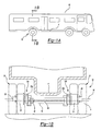
- FIGS 1A and 1B schematically illustrate a vehicle 10 incorporating an inverted portal axle system 12 adjacent a vehicle floor F.
- the inverted portal axle 12 includes a pair of side reduction gear system housings 14A, 14B interconnected by an axle center beam housing 16.
- An input 18 is positioned near one of the side reduction gear system housings 14A, 14B and a shaft assembly 20 connects the input 18 to the other side reduction gear system housings 14A, 14B.
- the shaft assembly 20 may include one or more axle segments.
- the shaft 20 defines an axle axis of rotation A.
- Each side reduction gear system housing 14A, 14B includes a wheel hub assembly 22 driven by a gear reducer (illustrated schematically at 26A, 26B) which is preferably a double stage reduction providing the required speed reduction.
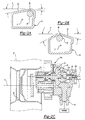
- the gear reduction 26A, 26B drives a spindle 28 (also illustrated in Figure 2C ), which drives the wheel hub assembly 22 and tires 23.
- the gear reduction 26A, 26B includes gearing to transfer the torque from the axle assembly 20 to the spindle 28 through the gear reduction 26A, 26B.
- the spindles 28 defines a wheel axis of rotation W.
- the wheel axis of rotation W is higher relative to the ground than the axle axis of rotation A.
- Tires 23 are mounted for rotation with the hub assemblies 22 as generally known.
- the shaft 20 is preferably offset located within the axle center beam housing 16.
- the axle shaft 20 is offset from a centerline C in the vertical and/or in the longitudinal within the axle center beam housing 16.
- the axle shaft 20 is preferably located in a recess 30 on the top wall 32 of the axle center beam housing 16.
- the top wall 32 of the center beam housing 16 is preferably shaped with slopes to maximize clearance to the bottom of the floor panels F ( Figure 1A ).
- the location of the recessed axle shaft can be anywhere longitudinally inside the axle center beam 16 (see one alternative position in Figure 2B ).
- the inverted portal axle system 12 includes a differential assembly (illustrated schematically at 33) which drives the shaft assembly 20.
- the axle assembly 20 preferably includes a short half-shaft 20a (differential side) and a long half-shaft 20b (opposite differential side).
- short and short are relative terms utilized for descriptive purposes and other shaft lengths, including equal length half-shafts, prop shafts and other rotating members, will benefit from the present invention.
- each gear reduction 26A, 26B is braked by disc brakes 34.
- the disc brakes 34 are integrated in the inverted portal axle system 12 and are typically air operated by a pneumatic cylinder 36, via shift lever or the like as is generally known. It should be understood that alternative type of actuation can also be used such as electromechanical, hydraulic, etc.
- the pneumatic brake cylinder 36 defines a cylinder axis P. Axis P is preferably angled within an angular range radially to the disc brake axis ( Figure 3B ).
- the clocking of the cylinder 36 around the wheel axis of rotation W of the side reduction gear system housing 14A, 14B from a generally vertical orientation to approximately 45 degrees with the vertical allows the inverted portal axle system 12 to provide less interference with the vehicle floor and thus a lower floor profile.
- the radially rotated brake cylinder 36 allows for better packaging of brake actuator, and suspension rod brackets.
- the combination of features of the present invention provides an inverted portal axle with capability of center beam drop of up to 150 - 160 mm, which allows the vehicle floor F over the axle to be reduced by 40 - 50 mm, which can result on a full flat floor or only a minor slope over the axle.
Landscapes
- Engineering & Computer Science (AREA)
- Mechanical Engineering (AREA)
- Vehicle Body Suspensions (AREA)
- Arrangement Of Transmissions (AREA)
- Motorcycle And Bicycle Frame (AREA)
Claims (19)
- Configuration inversée d'essieu de pont (12) comprenant :- un ensemble de corps d'essieu (20) définissant un axe de rotation d'essieu (A) ;- une première réduction par engrenage (26A) commandant une première broche (28) autour d'un axe de rotation (W) de roue placée à distance dudit axe de rotation (A) d'essieu, dans laquelle ledit axe de rotation (W) de roue est verticalement plus élevé par rapport au sol que ledit axe de rotation d'essieu (A) ;- une seconde réduction par engrenage (26B) commandant une seconde broche (28) autour dudit axe de rotation de roue (W), lesdites première (26A) et seconde (26B) réductions par engrenage étant commandées par ledit ensemble de corps d'essieu (20) ; et- un logement d'essieu (16) s'étendant entre lesdites première (26A) et seconde (26B) réductions par engrenage et définissant une ligne centrale de logement (C) décalée verticalement dudit axe de rotation (A) d'essieu, ledit logement d'essieu (16) définissant une cavité intérieure qui reçoit ledit ensemble de corps d'essieu (20), et dans lequel ledit axe de rotation (A) d'essieu est positionné verticalement entre ladite ligne centrale de logement (C) et ledit axe de rotation (W) de roue, caractérisée en ce que la ligne centrale de logement (C) est décalée longitudinalement dudit axe de rotation d'essieu.
- Configuration inversée d'essieu de pont (12) selon la revendication 1 dans laquelle ledit logement d'essieu (16) comporte une paroi de logement (32) dotée d'un évidement (30), ledit ensemble de corps d'essieu (20) étant placé à l'intérieur dudit évidement (30).
- Configuration inversée d'essieu de pont (12) selon la revendication 2 dans laquelle ladite paroi de logement comprend une paroi supérieure (32) dudit logement d'essieu (16) et dans laquelle ledit évidement (30) est défini par une surface qui est non symétrique autour de ladite ligne centrale de logement (C).
- Configuration inversée d'essieu de pont (12) selon la revendication 1 dans laquelle ledit logement d'essieu (16) comprend une paroi supérieure (32) qui est adaptée pour être inclinée par rapport à un plan horizontal défini par un plancher de véhicule.
- Configuration inversée d'essieu de pont (12) selon la revendication 1 comportant un premier cylindre de frein à air comprimé (36) fixé à ladite première réduction par engrenage (26A) et un second cylindre de frein à air comprimé (36) fixé à ladite seconde réduction par engrenage (26B), lesdits premier et second cylindres de frein à air comprimé (36) définissant chacun un axe de cylindre (P) qui est décalé de façon radiale autour de l'axe de rotation (W) de roue à partir d'une orientation verticale.
- Configuration inversée d'essieu de pont (12) selon la revendication 5 dans laquelle lesdits premier et second cylindres de frein à air comprimé (36) peuvent tourner dans les limites d'une plage angulaire située autour dudit axe de rotation de roue (W).
- Configuration inversée d'essieu de pont (12) selon la revendication 6, dans laquelle ledit axe de cylindre (P) correspondant à chacun desdits premier et second cylindres de frein à air comprimé (36) est orienté suivant un angle de quarante cinq degrés par rapport audit axe de rotation de roue (W).
- Configuration inversée d'essieu de pont (12) selon la revendication 1 comprenant un différentiel (33) couplé à une entrée (18), ledit différentiel (33) étant positionné latéralement plus près de l'une de ladite première (26A) et de ladite seconde (26B) réductions par engrenage que de l'autre de ladite première (26A) et de ladite seconde (26B) réductions par engrenage, et dans laquelle ledit différentiel (33) commande ledit ensemble de corps d'essieu (20).
- Configuration inversée d'essieu de pont (12) selon la revendication 1, comportant un différentiel (33) commandé par une entrée (18), dans laquelle ledit ensemble de corps d'essieu (20) est entraîné par ledit différentiel (33) autour dudit axe de rotation d'essieu (A), et dans laquelle ledit logement d'essieu (16) comporte une paroi de logement (32) dotée d'un évidement (30) qui reçoit ledit ensemble de corps d'essieu (20).
- Configuration inversée d'essieu de pont (12) selon la revendication 9, dans laquelle ladite entrée est adaptée pour recevoir une entrée venant d'un moteur et dans laquelle ledit axe de rotation d'essieu (A) est positionné sur un côté de ladite ligne centrale de logement (C) et le moteur doit être positionné sur un côté opposé de ladite ligne centrale de logement (C) par rapport au dudit axe de rotation d'essieu (A).
- Configuration inversée d'essieu de pont (12) selon la revendication 9 comportant un premier cylindre de frein à air comprimé (36) fixé à ladite première réduction par engrenage (26A) et un second cylindre de frein à air comprimé (36) fixé à ladite seconde réduction par engrenage (26B), lesdits premier et second cylindres de frein à air comprimé (36) définissant, chacun, un axe de cylindre (P) qui est décalé de façon radiale par rapport audit axe de rotation de roue (W) à partir d'une orientation verticale.
- Configuration inversée d'essieu de pont (12) selon la revendication 11, dans laquelle lesdits premier et second cylindres de frein à air comprimé peuvent tourner dans les limites d'une plage angulaire autour dudit axe de rotation de roue (A).
- Configuration inversée d'essieu de pont (12) selon la revendication 9, dans laquelle ladite paroi de logement comporte une paroi supérieure (32) qui coopère avec une paroi inférieure et des parois latérales en vue de définir une cavité intérieure.
- Configuration inversée d'essieu de pont (12) selon la revendication 13, dans laquelle ladite paroi supérieure (32) est définie par une surface supérieure qui est orientée obliquement par rapport aux dites parois latérales.
- Configuration inversée d'essieu de pont (12) selon la revendication 9 dans laquelle lesdites première (26A) et seconde (26B) réductions par engrenage comportent, chacune, une boîte d'engrenages de réduction à double étage.
- Configuration inversée d'essieu de pont (12) selon la revendication 9, dans laquelle ledit ensemble de corps d'essieu (20) comprend, au moins, un premier arbre (20a) et un second arbre (20b) qui est plus long que ledit premier arbre (20a), ladite première réduction par engrenage (26A) étant entraînée par l'un dudit premier (20a) et dudit second (20b) arbres, et ladite seconde réduction par engrenage (26B) étant entraînée par l'autre desdits premier (20a) et second (20b) arbres.
- Configuration inversée d'essieu de pont (12) selon la revendication 1, dans laquelle ledit logement d'essieu (16) comprend une paroi supérieure (32), une paroi inférieure, et des parois latérales interconnectant lesdites parois supérieure et inférieure, et dans laquelle ladite paroi supérieure comporte au moins une partie qui est orientée de façon oblique par rapport à ladite paroi inférieure.
- Configuration inversée d'essieu de pont selon la revendication 17, dans laquelle ladite paroi inférieure est généralement parallèle au sol, ladite au moins une partie s'étendant vers le haut à partir de l'une desdites parois latérales.
- Configuration inversée d'essieu de pont (12) selon la revendication 1, dans laquelle ledit logement d'essieu (16) comprend une paroi supérieure (32) et une paroi inférieure interconnectée avec ladite paroi supérieure (32) par des parois latérales, dans laquelle ladite paroi supérieure (32) comporte un évidement (30), ledit ensemble de corps d'essieu (20) étant placé à l'intérieur dudit évidement (30), et dans laquelle ledit évidement (30) est défini par une surface qui s'étend de façon oblique par rapport à ladite paroi inférieure, et ledit évidement (30) étant décalé longitudinalement et verticalement à partir de ladite ligne centrale du logement (C).
Applications Claiming Priority (1)
| Application Number | Priority Date | Filing Date | Title |
|---|---|---|---|
| PCT/IT2003/000270 WO2004096581A1 (fr) | 2003-05-02 | 2003-05-02 | Configuration inversee d'axe de porte pour vehicule a faible garde au sol |
Publications (2)
| Publication Number | Publication Date |
|---|---|
| EP1620276A1 EP1620276A1 (fr) | 2006-02-01 |
| EP1620276B1 true EP1620276B1 (fr) | 2008-07-16 |
Family
ID=33397891
Family Applications (1)
| Application Number | Title | Priority Date | Filing Date |
|---|---|---|---|
| EP03723088A Expired - Lifetime EP1620276B1 (fr) | 2003-05-02 | 2003-05-02 | Configuration inversee d'axe de porte pour vehicule a faible garde au sol |
Country Status (7)
| Country | Link |
|---|---|
| US (1) | US7364528B2 (fr) |
| EP (1) | EP1620276B1 (fr) |
| CN (1) | CN100439128C (fr) |
| AU (1) | AU2003230231A1 (fr) |
| BR (1) | BR0318287A (fr) |
| DE (1) | DE60322271D1 (fr) |
| WO (1) | WO2004096581A1 (fr) |
Families Citing this family (14)
| Publication number | Priority date | Publication date | Assignee | Title |
|---|---|---|---|---|
| WO2007001277A1 (fr) * | 2005-06-22 | 2007-01-04 | Mack Trucks, Inc. | Vehicule avec des composants agenges par rapport a un cadre de chassis |
| US8371589B2 (en) * | 2007-10-02 | 2013-02-12 | Arboc Technologies Llc | Mass transit vehicle |
| CA2701127C (fr) | 2007-10-02 | 2017-02-14 | Arboc Specialty Vehicles, Llc | Vehicule de transport collectif |
| DE102009033531A1 (de) * | 2009-07-10 | 2011-01-20 | Dr. Ing. H.C. F. Porsche Aktiengesellschaft | Antriebsvorrichtung für ein Kraftfahrzeug mit einer elektrische Maschinen aufweisenden Portalachse |
| DE102010010438A1 (de) * | 2010-02-26 | 2011-09-01 | Dr. Ing. H.C. F. Porsche Aktiengesellschaft | Fahrwerk für ein Kraftfahrzeug mit einer elektrichen Achse |
| US8925941B2 (en) * | 2011-10-13 | 2015-01-06 | Axletech International Ip Holdings, Llc | Modular independent suspension and method of producing the same |
| USD814979S1 (en) | 2016-06-06 | 2018-04-10 | Axletech International Ip Holdings, Llc | Suspension axle |
| CN119636298A (zh) | 2018-05-10 | 2025-03-18 | 艾里逊变速箱公司 | 用于低底盘车辆的车桥组件 |
| US11220149B2 (en) * | 2019-03-13 | 2022-01-11 | Zf Friedrichshafen Ag | Rear axle assembly designed to fit within rear axle envelope |
| US11888377B2 (en) | 2021-03-30 | 2024-01-30 | Arvinmeritor Technology, Llc | Axle assembly having an electric motor module |
| JP2024514543A (ja) * | 2021-03-30 | 2024-04-02 | ファン・ローケレン・カンパーニュ,ピーテル・テオドール | 低床バスで使用するための逆ポータルアクスル |
| US11685253B2 (en) | 2021-06-15 | 2023-06-27 | Arvinmeritor Technology, Llc | Drive axle system |
| US20240336122A1 (en) * | 2023-04-04 | 2024-10-10 | High Desert Racing Products, LLC | Dual motor ev axle system and method |
| US12589644B2 (en) | 2023-12-19 | 2026-03-31 | Arvinmeritor Technology, Llc | Drive axle system having an electric motor |
Family Cites Families (25)
| Publication number | Priority date | Publication date | Assignee | Title |
|---|---|---|---|---|
| FR658212A (fr) | 1927-12-10 | 1929-06-01 | Essieu-moteur avec réducteur de vitesses | |
| FR697929A (fr) * | 1929-09-24 | 1931-01-23 | Soc D Const Et D Entretien De | Essieu moteur pour voitures automobiles |
| DE577089C (de) | 1931-02-01 | 1933-05-23 | G & J Jaeger Akt Ges | Getriebelagerung fuer elektrisch angetriebene Kraftfahrzeuge |
| US2915920A (en) * | 1950-07-21 | 1959-12-08 | Rockwell Standard Co | Vehicle drive mechanism |
| DE1660787U (de) * | 1951-08-20 | 1953-08-06 | Normag Zorge G M B H | Kraftfahrzeugtriebachse, insbesondere fuer schlepper. |
| US3311186A (en) * | 1963-09-09 | 1967-03-28 | Simplicity Mfg Company | Riding tractor |
| US3340586A (en) | 1965-08-30 | 1967-09-12 | Singer Co | Methods and apparatus for needling textile fibers |
| GB1165217A (en) | 1965-10-22 | 1969-09-24 | Int Harvester Co | Four Wheel Drive for Vehicles |
| US3434364A (en) * | 1967-08-08 | 1969-03-25 | Rockwell Standard Co | Vehicle drive assembly |
| DE3027806C2 (de) | 1980-07-23 | 1984-10-31 | Zahnradfabrik Friedrichshafen Ag, 7990 Friedrichshafen | Triebachse für Omnibusse |
| CN2106111U (zh) * | 1989-10-16 | 1992-06-03 | 铁道部四方机车车辆工厂 | 整体压型制动缸 |
| IT1238922B (it) | 1990-05-07 | 1993-09-07 | Menarini S P A | Sistema di trazione per un autobus particolarmente per traffico locale |
| DE4201513C2 (de) | 1992-01-21 | 1995-01-05 | Man Nutzfahrzeuge Ag | Omnibus, insbesondere Niedrigstflurbus |
| CN2156089Y (zh) * | 1992-07-14 | 1994-02-16 | 铁道部大连机车车辆工厂 | 制动缸 |
| DE69313250T3 (de) | 1992-11-27 | 2000-12-21 | Magyar Vagon- Es Gepgyar, Gyoer | Achse für Fahrzeuge |
| US5699869A (en) * | 1995-05-25 | 1997-12-23 | Mattel, Inc. | Automatically engaging and disengaging gear box assembly |
| DE19604730A1 (de) | 1996-02-09 | 1997-08-14 | Zahnradfabrik Friedrichshafen | Portalachse |
| US6193007B1 (en) * | 1999-08-06 | 2001-02-27 | Mohinder Kumra | Rear suspension and drive axle assembly |
| US20030010561A1 (en) * | 2000-11-09 | 2003-01-16 | Bartel James J. | Low load floor motor vehicle |
| ES2236533T3 (es) * | 2001-04-30 | 2005-07-16 | Knorr-Bremse Systeme Fur Nutzfahrzeuge Gmbh | Cubo de rueda. |
| US6755093B2 (en) * | 2002-01-29 | 2004-06-29 | Meritor Heavy Vehicle Technology, Llc | Planetary drive assembly with idlers for low floor vehicle |
| US6793035B2 (en) * | 2002-03-15 | 2004-09-21 | Meritor Heavy Vehicle Technology, Llc | Semi-independent swing arm suspension system for a low floor vehicle |
| US6886655B2 (en) | 2002-08-09 | 2005-05-03 | Arvinmeritor Technology, Llc | Vehicle wheel end assembly with double reduction gear set |
| US6843746B2 (en) * | 2003-05-05 | 2005-01-18 | Arvinmeritor Technology, Llc | Dual level inverted portal axle lubrication configuration |
| US7048087B2 (en) * | 2003-08-26 | 2006-05-23 | Arvinmeritor Technology, Llc | External shaft low floor drive axle assembly |
-
2003
- 2003-05-02 WO PCT/IT2003/000270 patent/WO2004096581A1/fr not_active Ceased
- 2003-05-02 CN CNB038264021A patent/CN100439128C/zh not_active Expired - Lifetime
- 2003-05-02 BR BRPI0318287-8A patent/BR0318287A/pt not_active Application Discontinuation
- 2003-05-02 US US10/555,421 patent/US7364528B2/en not_active Expired - Fee Related
- 2003-05-02 AU AU2003230231A patent/AU2003230231A1/en not_active Abandoned
- 2003-05-02 EP EP03723088A patent/EP1620276B1/fr not_active Expired - Lifetime
- 2003-05-02 DE DE60322271T patent/DE60322271D1/de not_active Expired - Lifetime
Also Published As
| Publication number | Publication date |
|---|---|
| US7364528B2 (en) | 2008-04-29 |
| CN1771139A (zh) | 2006-05-10 |
| EP1620276A1 (fr) | 2006-02-01 |
| CN100439128C (zh) | 2008-12-03 |
| WO2004096581A1 (fr) | 2004-11-11 |
| US20070068723A1 (en) | 2007-03-29 |
| DE60322271D1 (de) | 2008-08-28 |
| BR0318287A (pt) | 2006-05-30 |
| AU2003230231A1 (en) | 2004-11-23 |
Similar Documents
| Publication | Publication Date | Title |
|---|---|---|
| EP1620276B1 (fr) | Configuration inversee d'axe de porte pour vehicule a faible garde au sol | |
| EP1391340B1 (fr) | Etage de transmission pour véhicule | |
| US6035956A (en) | Offset axle | |
| US7878936B2 (en) | Drive train for a motor vehicle and power divider therefor | |
| US20070186803A1 (en) | Axle for rail vehicle having a low-level floor, bogie and corresponding rail vehicle | |
| US6431298B1 (en) | Drive unit assembly for an electrically driven vehicle | |
| EP1475247B1 (fr) | Système de lubrification à double niveaux pour des essieux surbaissés | |
| US7048087B2 (en) | External shaft low floor drive axle assembly | |
| EP1344661B1 (fr) | Système de suspension pour un véhicule à plancher bas | |
| EP1253038B1 (fr) | Système de suspension indépendante | |
| EP1348587A2 (fr) | Système de suspension pour un véhicule à plancher rabaissé | |
| EP1388452A2 (fr) | Ensemble terminal d'une roue de véhicule | |
| EP0966361B1 (fr) | Dispositif d'entrainement, en particulier pour autobus | |
| US7204339B2 (en) | Vehicle wheel end assembly with wheel adapter | |
| CN116001544A (zh) | 电动叉车高集成平行双驱系统 | |
| CN100430256C (zh) | 门式车桥 | |
| JPH0515131Y2 (fr) | ||
| CN1397749A (zh) | 互锁差速传动装置 | |
| US20030155170A1 (en) | Drive assembly for low floor vehicle |
Legal Events
| Date | Code | Title | Description |
|---|---|---|---|
| PUAI | Public reference made under article 153(3) epc to a published international application that has entered the european phase |
Free format text: ORIGINAL CODE: 0009012 |
|
| 17P | Request for examination filed |
Effective date: 20051028 |
|
| AK | Designated contracting states |
Kind code of ref document: A1 Designated state(s): DE FR GB IT SE |
|
| DAX | Request for extension of the european patent (deleted) | ||
| RBV | Designated contracting states (corrected) |
Designated state(s): DE FR GB IT SE |
|
| 17Q | First examination report despatched |
Effective date: 20070625 |
|
| GRAP | Despatch of communication of intention to grant a patent |
Free format text: ORIGINAL CODE: EPIDOSNIGR1 |
|
| GRAS | Grant fee paid |
Free format text: ORIGINAL CODE: EPIDOSNIGR3 |
|
| GRAA | (expected) grant |
Free format text: ORIGINAL CODE: 0009210 |
|
| AK | Designated contracting states |
Kind code of ref document: B1 Designated state(s): DE FR GB IT SE |
|
| REG | Reference to a national code |
Ref country code: GB Ref legal event code: FG4D |
|
| REF | Corresponds to: |
Ref document number: 60322271 Country of ref document: DE Date of ref document: 20080828 Kind code of ref document: P |
|
| REG | Reference to a national code |
Ref country code: SE Ref legal event code: TRGR |
|
| PLBE | No opposition filed within time limit |
Free format text: ORIGINAL CODE: 0009261 |
|
| STAA | Information on the status of an ep patent application or granted ep patent |
Free format text: STATUS: NO OPPOSITION FILED WITHIN TIME LIMIT |
|
| 26N | No opposition filed |
Effective date: 20090417 |
|
| REG | Reference to a national code |
Ref country code: FR Ref legal event code: PLFP Year of fee payment: 13 |
|
| REG | Reference to a national code |
Ref country code: FR Ref legal event code: PLFP Year of fee payment: 14 |
|
| REG | Reference to a national code |
Ref country code: FR Ref legal event code: PLFP Year of fee payment: 15 |
|
| REG | Reference to a national code |
Ref country code: FR Ref legal event code: PLFP Year of fee payment: 16 |
|
| PGFP | Annual fee paid to national office [announced via postgrant information from national office to epo] |
Ref country code: SE Payment date: 20220527 Year of fee payment: 20 Ref country code: IT Payment date: 20220523 Year of fee payment: 20 Ref country code: GB Payment date: 20220527 Year of fee payment: 20 Ref country code: FR Payment date: 20220525 Year of fee payment: 20 Ref country code: DE Payment date: 20220527 Year of fee payment: 20 |
|
| REG | Reference to a national code |
Ref country code: DE Ref legal event code: R071 Ref document number: 60322271 Country of ref document: DE |
|
| REG | Reference to a national code |
Ref country code: GB Ref legal event code: PE20 Expiry date: 20230501 |
|
| P01 | Opt-out of the competence of the unified patent court (upc) registered |
Effective date: 20230522 |
|
| REG | Reference to a national code |
Ref country code: SE Ref legal event code: EUG |
|
| PG25 | Lapsed in a contracting state [announced via postgrant information from national office to epo] |
Ref country code: GB Free format text: LAPSE BECAUSE OF EXPIRATION OF PROTECTION Effective date: 20230501 |