EP1620310B1 - Aerodyne avec un fuselage generant une portance - Google Patents
Aerodyne avec un fuselage generant une portance Download PDFInfo
- Publication number
- EP1620310B1 EP1620310B1 EP04741518A EP04741518A EP1620310B1 EP 1620310 B1 EP1620310 B1 EP 1620310B1 EP 04741518 A EP04741518 A EP 04741518A EP 04741518 A EP04741518 A EP 04741518A EP 1620310 B1 EP1620310 B1 EP 1620310B1
- Authority
- EP
- European Patent Office
- Prior art keywords
- flight device
- wings
- fuselage
- profile
- span
- Prior art date
- Legal status (The legal status is an assumption and is not a legal conclusion. Google has not performed a legal analysis and makes no representation as to the accuracy of the status listed.)
- Expired - Lifetime
Links
- 241000251468 Actinopterygii Species 0.000 claims abstract 2
- 239000003381 stabilizer Substances 0.000 claims description 8
- 239000012530 fluid Substances 0.000 claims description 7
- 230000007704 transition Effects 0.000 claims description 6
- 230000008719 thickening Effects 0.000 claims description 4
- 230000009194 climbing Effects 0.000 claims 1
- 230000008901 benefit Effects 0.000 description 15
- 238000009826 distribution Methods 0.000 description 12
- 238000013461 design Methods 0.000 description 11
- 230000005484 gravity Effects 0.000 description 11
- 238000010276 construction Methods 0.000 description 7
- 239000000446 fuel Substances 0.000 description 6
- 238000009434 installation Methods 0.000 description 6
- 239000011295 pitch Substances 0.000 description 6
- 230000001965 increasing effect Effects 0.000 description 5
- 230000035939 shock Effects 0.000 description 4
- 238000005452 bending Methods 0.000 description 3
- 230000008859 change Effects 0.000 description 3
- 238000012423 maintenance Methods 0.000 description 3
- 230000007935 neutral effect Effects 0.000 description 3
- 230000006641 stabilisation Effects 0.000 description 3
- 238000011105 stabilization Methods 0.000 description 3
- 230000000694 effects Effects 0.000 description 2
- 230000002349 favourable effect Effects 0.000 description 2
- 230000001976 improved effect Effects 0.000 description 2
- 230000003716 rejuvenation Effects 0.000 description 2
- 238000007493 shaping process Methods 0.000 description 2
- 208000010201 Exanthema Diseases 0.000 description 1
- 238000009825 accumulation Methods 0.000 description 1
- 230000002411 adverse Effects 0.000 description 1
- 238000013459 approach Methods 0.000 description 1
- 230000015572 biosynthetic process Effects 0.000 description 1
- 230000015556 catabolic process Effects 0.000 description 1
- 230000008878 coupling Effects 0.000 description 1
- 238000010168 coupling process Methods 0.000 description 1
- 238000005859 coupling reaction Methods 0.000 description 1
- 230000001419 dependent effect Effects 0.000 description 1
- 238000006073 displacement reaction Methods 0.000 description 1
- 201000005884 exanthem Diseases 0.000 description 1
- 230000006872 improvement Effects 0.000 description 1
- 230000001939 inductive effect Effects 0.000 description 1
- 230000010354 integration Effects 0.000 description 1
- 230000001788 irregular Effects 0.000 description 1
- 238000000034 method Methods 0.000 description 1
- 230000002028 premature Effects 0.000 description 1
- 230000008569 process Effects 0.000 description 1
- 230000000750 progressive effect Effects 0.000 description 1
- 238000005086 pumping Methods 0.000 description 1
- 206010037844 rash Diseases 0.000 description 1
- 230000003014 reinforcing effect Effects 0.000 description 1
- 230000000087 stabilizing effect Effects 0.000 description 1
- 230000004083 survival effect Effects 0.000 description 1
- 239000000725 suspension Substances 0.000 description 1
- 238000012360 testing method Methods 0.000 description 1
- 238000009827 uniform distribution Methods 0.000 description 1
Images






Classifications
-
- B—PERFORMING OPERATIONS; TRANSPORTING
- B64—AIRCRAFT; AVIATION; COSMONAUTICS
- B64C—AEROPLANES; HELICOPTERS
- B64C1/00—Fuselages; Constructional features common to fuselages, wings, stabilising surfaces or the like
- B64C1/0009—Aerodynamic aspects
-
- B—PERFORMING OPERATIONS; TRANSPORTING
- B64—AIRCRAFT; AVIATION; COSMONAUTICS
- B64C—AEROPLANES; HELICOPTERS
- B64C3/00—Wings
- B64C3/10—Shape of wings
-
- B—PERFORMING OPERATIONS; TRANSPORTING
- B64—AIRCRAFT; AVIATION; COSMONAUTICS
- B64C—AEROPLANES; HELICOPTERS
- B64C39/00—Aircraft not otherwise provided for
- B64C39/10—All-wing aircraft
-
- B—PERFORMING OPERATIONS; TRANSPORTING
- B64—AIRCRAFT; AVIATION; COSMONAUTICS
- B64U—UNMANNED AERIAL VEHICLES [UAV]; EQUIPMENT THEREFOR
- B64U10/00—Type of UAV
- B64U10/25—Fixed-wing aircraft
-
- B—PERFORMING OPERATIONS; TRANSPORTING
- B64—AIRCRAFT; AVIATION; COSMONAUTICS
- B64U—UNMANNED AERIAL VEHICLES [UAV]; EQUIPMENT THEREFOR
- B64U30/00—Means for producing lift; Empennages; Arrangements thereof
- B64U30/10—Wings
-
- B—PERFORMING OPERATIONS; TRANSPORTING
- B64—AIRCRAFT; AVIATION; COSMONAUTICS
- B64U—UNMANNED AERIAL VEHICLES [UAV]; EQUIPMENT THEREFOR
- B64U50/00—Propulsion; Power supply
- B64U50/10—Propulsion
- B64U50/11—Propulsion using internal combustion piston engines
-
- B—PERFORMING OPERATIONS; TRANSPORTING
- B64—AIRCRAFT; AVIATION; COSMONAUTICS
- B64U—UNMANNED AERIAL VEHICLES [UAV]; EQUIPMENT THEREFOR
- B64U60/00—Undercarriages
- B64U60/50—Undercarriages with landing legs
-
- B—PERFORMING OPERATIONS; TRANSPORTING
- B64—AIRCRAFT; AVIATION; COSMONAUTICS
- B64C—AEROPLANES; HELICOPTERS
- B64C1/00—Fuselages; Constructional features common to fuselages, wings, stabilising surfaces or the like
- B64C2001/0045—Fuselages characterised by special shapes
-
- B—PERFORMING OPERATIONS; TRANSPORTING
- B64—AIRCRAFT; AVIATION; COSMONAUTICS
- B64C—AEROPLANES; HELICOPTERS
- B64C39/00—Aircraft not otherwise provided for
- B64C39/10—All-wing aircraft
- B64C2039/105—All-wing aircraft of blended wing body type
-
- B—PERFORMING OPERATIONS; TRANSPORTING
- B64—AIRCRAFT; AVIATION; COSMONAUTICS
- B64U—UNMANNED AERIAL VEHICLES [UAV]; EQUIPMENT THEREFOR
- B64U2101/00—UAVs specially adapted for particular uses or applications
- B64U2101/60—UAVs specially adapted for particular uses or applications for transporting passengers; for transporting goods other than weapons
-
- Y—GENERAL TAGGING OF NEW TECHNOLOGICAL DEVELOPMENTS; GENERAL TAGGING OF CROSS-SECTIONAL TECHNOLOGIES SPANNING OVER SEVERAL SECTIONS OF THE IPC; TECHNICAL SUBJECTS COVERED BY FORMER USPC CROSS-REFERENCE ART COLLECTIONS [XRACs] AND DIGESTS
- Y02—TECHNOLOGIES OR APPLICATIONS FOR MITIGATION OR ADAPTATION AGAINST CLIMATE CHANGE
- Y02T—CLIMATE CHANGE MITIGATION TECHNOLOGIES RELATED TO TRANSPORTATION
- Y02T50/00—Aeronautics or air transport
- Y02T50/10—Drag reduction
Definitions
- the present invention relates to a new aircraft, in particular an aircraft, which is characterized by a new shape.
- Conventional aircraft have a cylindrical fuselage for the passengers or cargo, a lift wing, and a tail for maintaining flight stability.
- the wings have a large extension, but this has the disadvantage that great forces are created by the large bending moments and the wing must be built accordingly massive.
- the usable volume in conventional aircraft is small in relation to the external dimensions and the wetted surface.
- the lift, which is generated by larger wings, is partially offset by the additional weight.
- flying wings flying wings
- the hull is designed so that this buoyancy generated.
- the tail is omitted. You can even go so far and integrate the hull completely in the wing to achieve better flight performance.
- tailplane flight performance is accomplished by wing and pitch control, as well as longitudinal stabilizer stability, a brushless aircraft must perform all three wing tasks. A substantial part of the wing must perform these tasks and can not be designed for lift generation. Therefore, a larger wing area is needed than with a tailplane.
- flying wings only have a short tail lever arm, they are very sensitive to the center of gravity. Because of the coupling of the parameters, they are difficult to interpret.
- the wing of an aircraft can be kept smaller. It is even possible to design the fuselage of the aircraft so that the fuselage at high airspeeds required buoyancy can generate itself. In this case, wings are no longer needed.
- Such aircraft are called Lifting Body. Due to the low extension of the lifting surface, lifting bodysuits have the disadvantage that the induced resistance at high angles of attack can become very high. Another disadvantage of such a construction is that a high speed is required for take-off and landing.
- the document US-A-5 769 358 shows an aircraft with a buoyancy-inducing fuselage which progressively tapers in the first fifth and with two wings, the area of projection of both wings in a horizontal plane being less than forty percent of the total buoyancy area and with a tailplane on the last fifth of the fuselage.
- Document GB-A-1 220 055 shows in Figs. 6 and 7 a flying wing without tailplane wherein for the purpose of providing stability about the pitch axis, the longitudinal center profile of the aircraft has either no or negative camber, the longitudinal profile of the wings is positive is arched, the profile of the hull has a positive moment coefficient, and the profile of the wings has a negative moment coefficient.
- the object of the invention is now to propose an aircraft which has a small extension, but at the same time has good sliding properties.
- Another object of the present invention is to achieve good controllability.
- Another object of the present invention is to achieve the best possible efficiency for the engine installation.
- Another object of the invention is to obtain the best possible efficiency of the inlet and the engine for the most important phases of flight (take-off, climb, cruise, etc.).
- Another object of the invention is to substantially prevent the suction of foreign objects into the engine during take-off and landing.
- Another object of the invention is to build an aircraft in which the additional resistance caused by the engine plant is reduced.
- Another object of the invention is to design the aerodynamics and thus the shape of the aircraft so that there is plenty of space for the installation of the drive and all systems, and that the location of these installations can be used to adjust the center of gravity.
- Another object of the present invention is to reduce operating costs as compared to conventional aircraft.
- Another object of the present invention is to increase the chances of survival of the passengers in the event of an accident.
- Another goal is to reduce the noise emission from such aircraft.
- Another object of the present invention is to increase the economic cruising speed.
- Another object of the present invention is to reduce the minimum speed and thus reduce the takeoff and landing speed of such an aircraft.
- Another object of the present invention is to achieve the best possible flight performance, especially in slow flight.
- Another object of the present invention is to reduce trim forces over the entire speed range.
- an aircraft with a buoyancy-generating fuselage, which progressively tapers in the first fifth and the last fifth, two wings, the area of projection of both wings in a horizontal plane being less than forty percent of the total buoyancy area , a tailplane on the last fifth of the fuselage, wherein the longitudinal center profile of the aircraft has a negative curvature, and wherein the longitudinal profile of the wings is positively curved.
- the trunk (or the skeleton line of the trunk) is slightly arched down, while the wings (or the skeleton line of the wings) are at least partially arched upwards.
- the maximum span of the wings between 60% and 80% of the length of the hull to lie, but preferably between 66% and 80%.
- the pressure point and thus the center of gravity shift backwards.
- the aircraft can be balanced more easily, since now the engine comes closer to the center of gravity.
- Another advantage of the relatively far back center of gravity is the possibility that can be realized by a short main landing gear, which in turn results in advantages in weight and air resistance.
- the stability is achieved according to the invention by an aircraft, with a buoyancy generating hull, the largest span in the third and fourth fifths of the total length and the floor plan progressively tapers in the first fifth and in the last fifth and has wings.
- the area of projection of both wings in a horizontal plane represents less than 40, preferably less than 30, more preferably less than 20 percent of the projection in a horizontal plane of the total lifting surface. They are at the third and fourth fifth of the total length of the named hull.
- the aircraft has a tailplane on the last fifth of the fuselage, the span of which is preferably at least 90% of the span in the third or fourth fifth of the fuselage.
- the aircraft according to the invention differs from known aircraft also by a new distribution of the buoyancy surface along the longitudinal axis of conventional aircraft.
- the ratio between the lift area of the third and fourth fifths of the aircraft including the wings, and the lift area of the first and second fifths of the aircraft is preferably between 1.5 and 3.0, while the ratio between the lift area of the designated third and fourth fifths of the aircraft, including the Wings, and the buoyancy of the last fifth of the hull is between 5.0 and 15.
- the buoyancy of the last fifth of the fuselage but is about the same size or even slightly smaller than the buoyancy of the first fifth of the aircraft.
- This construction has the advantage that it can be very compact.
- the small span provided by a buoyancy-generating hull and small wings makes the torques on the structure smaller than in conventional aircraft, so that the support structure can be made lighter yet stable.
- This construction also has the advantage that the almost optimal distribution of the cross sections of the aircraft along the longitudinal axis of the aircraft Aircraft allows a higher economic travel speed in the transonic area.
- the aerodynamics and thus the shape of the aircraft is also designed so that the main landing gear can be made as short and lightweight as possible.
- the wings are small and horizontal, or almost horizontal.
- the area of projection of both wings in a vertical plane represents less than 60 percent of the area of projection of both wings in a horizontal plane. Since there is a tail, such an aircraft can be easily controlled. Instead of with ailerons on the wings, the control takes place around the longitudinal axis only by mutual rash of the elevator.
- the cockpit is preferably mounted in a bead-like thickening on the upper side of the fuselage, wherein the named thickening is the same length as the named hull. As a result, the interference resistance between the cockpit and the fuselage is minimized.
- An elliptical buoyancy distribution is the most efficient way to create buoyancy with a flat wing.
- Small-stretch wings have almost elliptical buoyancy distributions for a wide range of rejuvenation and sweep. Wings with a large extension are much more delicate in this respect, because it does not take much to deal with another one Rejuvenation of the wing or a not quite correct setting of the wing to change the buoyancy distribution.
- the harmful resistance of bodies around which it flows is the least when the flow can flow three-dimensionally around the body.
- the lifting surface is designed so that it can be flowed around three-dimensionally.
- FIG. 1 shows an example of the plan of a hull, which acts as a lifting surface and is designed according to this principle.
- the figure 1 to shows a further embodiment.
- the plan of the fuselage corresponds to a symmetrical profile whose thickness (span) corresponds to 50% of the length.
- the floor plan and the side elevation of the described basic form both have aerodynamic profiles, in contrast to conventional aircraft in which only the side elevation is aerodynamically advantageous.
- the harmful resistance is minimal.
- the induced resistance is however large due to the small extension. Where the side edges are approximately parallel, ie approximately at the location of the largest span 11, a pressure equalization occurs at low angles of attack. Air from the lift surface bottom flows on the lift surface top. This effect takes place already before the largest span is reached. The larger the angle of attack and thus the buoyancy, the further ahead the air starts from the bottom of the lift surface the buoyancy surface top to flow. So, just at this point, a small wing 2 must be attached. As a result, the induced resistance can be substantially reduced. According to the invention, the buoyancy surface of the fuselage and the wings then looks as shown in FIGS. 2 and 2bis.
- the wing leading edge is directed strongly forward on the inside and has a front to back first concave and then convex shape. Aerodynamic tests have shown that the flight characteristics are optimal when the angle of the tangent of the named curve at the point of inflection 23 between the concave segment and the convex segment an angle between 10 ° and 55 °, preferably between 25 and 55 °, to the longitudinal axis 12 of Flying machine, and when this turning point 23 is located approximately in the middle of the wing leading edge.
- the trailing edge 20 of the wings has an angle normal to the longitudinal axis 12 of the aircraft on the wingtip 22.
- the trailing edge at an angle between 45 ° and 135 °, preferably between 60 ° and 120 °, but preferably between 70 ° and 110 °, but preferably between 80 ° and 100 ° to the longitudinal axis 12 of the aircraft. So the edge vortices are not pulled inward.
- the transition between the hull and the wings 2 is seamless (Figure 3 and 3bis). So it can not be said exactly where the hull 1 stops and where the wings 2 begin. This largely avoids the causes of harmful interference resistance.
- the hull and the wings can be designed as one unit.
- the longitudinal central profile is approximately symmetrical. This is achieved, for example, in that the longitudinal profile of the aircraft has no or only a negative curvature (FIG. 8).
- the longitudinal profile of the wings may be slightly arched positively (Figure 9).
- the profiles of the fuselage and the wings have a different zero buoyancy angle.
- the profile of the wings and the profile of the fuselage are designed in such a way that both do not generate lift at a certain angle of attack of the aircraft. This is achieved by placing the profile of the wing at a pitch angle a few degrees smaller than the profile of the fuselage.
- the pitch angle difference between the profile of the wings and the profile of the fuselage is approximately equal to the sum of the zero buoyancy angles.
- the pitch angle difference between the profile of the wings and the profile of the fuselage is approximately equal to the difference in zero buoyancy angles.
- the wings also have a symmetrical profile, but have a smaller angle of attack than the fuselage.
- trim resistance By using profiles with no or very little curvature, the trim resistance can be kept small.
- Another advantage of this measure is the improvement of flight performance and flight characteristics in slow flight. This is because the induced angle of attack of the wings by the 3-D flow around the hull is greater than the angle of attack of the fuselage. In order to prevent or delay premature tearing off of the flow at the wings, it is advantageous if the leading edge in this area is pulled downwards, ie. used a profile with positive curvature for the wings, and in addition, if the angle of attack of the wings is chosen smaller than the angle of attack of the fuselage.
- the pressure distribution is not adversely affected by this change, as in small-pitched blades the buoyancy distribution over a wide range of pitches and plan is largely elliptical.
- the lever arm must be long enough so that a small enough moment can be generated with small control forces.
- a longer lever arm also has the advantage that the trim resistance is reduced. To ensure this, it is advantageous if the tail unit 4 is arranged as far back as possible on the fuselage, as shown in FIG.
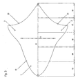
- the cockpit 1 can be partially integrated in the hull 1. It is advantageous if the cockpit 1 and the fuselage have approximately the same length and if the transition between cockpit and fuselage is designed to be fluid, as illustrated in FIG. 5:
- the pressure distribution on the fuselage and wing is virtually identical for the same wing / fuselage depth.
- the variation is just small. This means that there is little or no interference resistance.
- a very flat buoyancy distribution i. A constant as possible buoyancy coefficient for the entire buoyancy surface, has the further advantage that thereby the occurrence of shocks / shock waves occurs only at higher speeds than in a buoyancy surface, which has an irregular buoyancy distribution and thus areas with a large buoyancy coefficient.
- the shape of the aircraft according to the invention makes it possible to solve this problem by defining and symmetrically stabilizing the point at which the perturbation occurs due to the shaping of the leading edge.
- the sweep of the leading edge increases with increasing span. This favors the creation of a vortex. From a certain point of the span then the sweep of the span becomes smaller again. The vortex bursts approximately where the sweep of the leading edge is again smaller, possibly something behind.
- the slow flight characteristics are significantly influenced by the vortex.
- the aircraft according to the invention therefore has favorable low-speed flight characteristics.
- a disadvantage can be the high attack angle at takeoff and landing, which is higher than with conventional aircraft. As a result, the suspension is longer, resulting in more weight and air resistance. This disadvantage can be minimized by designing the lifting surface so that the neutral point / pressure point and thus also the center of gravity are relatively far behind. This can be achieved, for example, by the point of maximum wing span being 60% to 80%, preferably 66.66 to 80%, the hull length comes to rest. As a result, the chassis can be arranged further back and designed accordingly shorter.
- tailplane can be used as an aileron with appropriate design, it is not necessary to attach aileron to the fuselage or wing. This allows a design with very few moving parts (control surfaces).
- the output forces on the horizontal stabilizer with a suitable design of the lift surface are relatively low , resulting in a low trim resistance. Also, with such a construction no artificial stabilization is necessary.
- Another advantage of the present invention is that the circumference increases steadily to approximately the middle of the length of the aircraft. This leads to a thin boundary layer, which in turn is favorable to produce little air resistance.
- Another advantage of the present invention is the opportunity for engine installation resulting from the large volume. If a single fixed inlet was arranged per engine, there would be a loss of thrust at take-off and ascent, while resistance would be in cruising flight, since some of the air outside must flow around the intake.
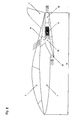
- this problem is solved by integrating the engine or engines 6 in the fuselage 1, as can be seen in FIG. This is possible thanks to the large internal volume resulting from the overall concept.
- auxiliary air inlets 61 on the fuselage top allow the attachment of auxiliary air inlets 61 on the fuselage top (wing top).
- auxiliary air inlets 61 on the fuselage top are closed, so that only smaller, on the hull bottom (airfoil) arranged air inlets 60 are used.
- the overall efficiency of the drive is increased because, on the one hand, the boundary layer on the underside of the wing is thinner, and on the other hand, because the local Anströchachiere on the bottom is much smaller than on the top.
- the auxiliary air inlets 61 are preferably integrated concurrently in the profile of the top; closed, they form an approximately smooth outer surface on the fuselage top. So that they are automatically closed during cruising, they are preferably provided with non-illustrated automatic check valves or valves. As soon as the pressure on the outside of the check valves 62 is less than the pressure on the inside, for example during cruising, these flaps are closed. When lifting, however, the valves are automatically opened by the negative pressure, so that more air enters the engines and a maximum thrust is obtained.
- the airflows from the upper and lower inlets are concentrically merged in an airbox 62 integrated in the fuselage.
- the airflow from the bottom of the inlet (s) 60 is directed to the center of the airbox while the airflow from the upper auxiliary inlets 61 is directed inwardly via an annular slot or surface 64.
- the trailing edge of this annular slot 64 is provided with a lip with a large radius. This inlet lip is necessary so that the flow at the engine inlet does not tear off.
- the lower inlet 60 is closed during the takeoff flight, so that as much as possible no dirt is sucked into the engine.
- This inlet can be closed, for example, as long as the landing gear is extended.
- the gas outlet 63 of the engine or engines is located at the end of the hull 1 and preferably has a circular or approximately circular cross-section. In the case of two engines, each outlet has a semicircular cross-section, so that the outlet cross-section is again in total circular.
- Another advantage of the design is the fact that an unillustrated spar can be provided behind the cockpit 3. This is a problem with conventional aircraft designs. Since a reinforcing spar is often performed under the fuselage, but which leads to an additional air resistance.
- the engines 6 are in voluminous buoyancy, and are carried by neither the wings 2 nor slender pylons.
- the inventive design has the further advantage of being able to accommodate significantly more volume than a conventional cylinder hull, whereby the space available per passenger can be increased or bulky loads can be carried. There is more space available for equipment installation, which can improve accessibility for maintenance.
- V L ⁇ l ⁇ L ⁇ l k where the factor k is between 10 and 60, typically around 30.
- a low-stretch aircraft which consists of a combination of most of the previously described features.
- the shaping of the lifting surface of the induced and the harmful resistance can be reduced and the horizontal stabilizer can additionally be arranged so that the harmful resistance is further reduced.
- the engine (s) By integrating the engine (s) into the fuselage, optimum efficiency for the intake / engine combination can be achieved.
- Such an aircraft will require very little power in cruising flight, because on the one hand the weight is low due to the compact design, and on the other hand the air resistance will be very small by the measures described above.
- such an aircraft is very simple, there are no landing flaps or the like necessary, only for the control are transverse, elevator and rudder necessary.
- a sports aircraft could be powered by a turbine at the stern. As a result, the flow around the hull is disturbed only minimally.
- the claimed aircraft may be large enough to carry passengers and / or cargo, or built as a model aircraft, unmanned aerial vehicle, drone, etc.
Landscapes
- Engineering & Computer Science (AREA)
- Aviation & Aerospace Engineering (AREA)
- Mechanical Engineering (AREA)
- Chemical & Material Sciences (AREA)
- Combustion & Propulsion (AREA)
- Remote Sensing (AREA)
- Physics & Mathematics (AREA)
- Fluid Mechanics (AREA)
- Toys (AREA)
- Types And Forms Of Lifts (AREA)
- Preparation Of Compounds By Using Micro-Organisms (AREA)
- Optical Record Carriers And Manufacture Thereof (AREA)
Claims (40)
- Aérodyne avec:un fuselage (1) générant une portance, dont le contour s'effile progressivement dans le premier cinquième (13) et dans le dernier cinquième (18),deux ailes (2), la surface de la projection des deux ailes dans un plan horizontal représentant moins de quarante pourcent de la surface de portance totale,un empennage d'altitude (4) au cinquième postérieur (18) du fuselage (1),le profile longitudinal médian de l'aérodyne ne comportant soit aucun renflement soit un renflement négatif,et le profile longitudinal des ailes étant cambré positivement.
- L'aérodyne de la revendication 1, dans lequel le profile longitudinal médian de l'aérodyne possède une cambrure au moins partiellement négative.
- L'aérodyne de la revendication 2, dans lequel la plus grande envergure (11) du fuselage (1) générant une portance est située dans le troisième (15) ou quatrième (17) cinquième de la longueur totale, et dans lequel la plus grande envergure des ailes se situe dans le quatrième (17) cinquième de la longueur totale dudit fuselage.
- Aérodyne selon la revendication 3, dont la plus grande envergure (11) se situe entre 40% et 80% de la longueur totale dudit fuselage.
- Aérodyne selon la revendication 4, dont la plus grande envergure (11) se situe entre 66% et 80% de la longueur totale dudit fuselage.
- Aérodyne selon l'une des revendications 1 à 4, dans lequel le profile du fuselage possède un coefficient de moment positif tandis que le profile des ailes possède un coefficient de moment négatif.
- Aérodyne selon l'une des revendications 1 à 6, dans lequel la surface de la projection des deux ailes (2) dans un plan horizontal représente moins de trente pourcent de la surface de portance totale.
- Aérodyne selon l'une des revendications 1 à 7, dans lequel la surface de la projection des deux ailes (2) dans un plan horizontal représente moins de vingt pourcent de la surface de portance totale.
- Aérodyne selon l'une des revendications 1 à 8, dans lequel la surface de la projection des deux ailes (2) dans un plan vertical représente moins de 60 pourcent de la surface de la projection des deux ailes dans un plan horizontal.
- Aérodyne selon l'une des revendications 1 à 9, dans lequel l'envergure dudit empennage d'altitude (4) représente au moins 90% de l'envergure maximale du fuselage (1).
- Aérodyne selon l'une des revendications 1 à 10, dans lequel le rapport entre la surface de portance dudit troisième (15) et du quatrième (17) cinquième de l'aérodyne y compris les ailes, et la surface de portance du premier (13) et du deuxième (14) cinquième de l'aérodyne se situe entre 1.5 et 3.0,
et dans lequel le rapport entre la surface de portance dudit troisième (15) et quatrième (17) cinquième de l'aérodyne, y compris les ailes, et la surface de portance du dernier cinquième (18) du fuselage se situe entre 5.0 et 15. - Aérodyne selon l'une des revendications 1 à 11, avec un habitacle (3), qui est placé en partie dans un renflement (16) sur la face supérieure du fuselage, ledit renflement (16) étant aussi long que ledit fuselage (1).
- Aérodyne selon la revendication 12, dans lequel ledit habitacle (3) est partiellement intégré dans ledit fuselage (1).
- Aérodyne selon l'une des revendications 1 à 13, dans lequel la configuration totale présente des transitions fluides, de sorte qu'il n'est pas précisément reconnaissable où ledit fuselage (1) finit et où lesdites ailes (2) commencent.
- Aérodyne selon l'une des revendications 1 à 14, dans lequel le bord de fuite (20) desdites ailes (2) à l'extrémité d'aile (22) forme un angle entre 60° et 120° avec l'axe longitudinal (12) de l'aérodyne.
- Aérodyne selon la revendication 15, dans lequel le bord de fuite (20) desdites ailes (2) à l'extrémité d'aile (22) forme un angle entre 70° et 110° avec l'axe longitudinal (12) de l'aérodyne.
- Aérodyne selon la revendication 16, dans lequel le bord de fuite (20) desdites ailes (2) à l'extrémité d'aile (22) forme un angle entre 80° et 100° avec l'axe longitudinal (12) de l'aérodyne.
- Aérodyne selon la revendication 17, dans lequel le bord de fuite (20) desdites ailes (2) à l'extrémité d'aile (22) forme un angle de 90° avec l'axe longitudinal (12) de l'aérodyne.
- Aérodyne selon l'une des revendications 1 à 18, dans lequel le bord d'attaque (21) desdites ailes (2) présente une forme, de l'avant vers l'arrière, d'abord concave et ensuite convexe, et dans lequel l'angle de la tangente de ladite courbe au point d'inflexion (23) entre le segment concave et le segment convexe forme un angle entre 10° et 55° avec l'axe longitudinal (12) de l'aérodyne.
- Aérodyne selon l'une des revendications 1 à 19, dans lequel les ailes (2) présentent un angle d'attaque plus petit que le fuselage générant une portance.
- Aérodyne selon l'une des revendications 1 à 20, dans lequel le pilotage autour de l'axe longitudinal a lieu uniquement par braquage en sens opposé dudit empennage d'altitude (4).
- Aérodyne selon l'une des revendications 1 à 21, dans lequel les bords d'attaque (10) gauche et droit de la pointe de l'aérodyne jusqu'à ladite plus grande envergure présente une forme, de l'avant vers l'arrière, d'abord convexe, puis concave et ensuite à nouveau convexe.
- Aérodyne selon l'une des revendications 1 à 22, qui présente une élongation de λ<3 (λ=l 2 /S, où I représente l'envergure des ailes et S la surface des ailes).
- Aérodyne selon l'une des revendications 1 à 22, dans lequel le rapport entre la longueur (12) et l'envergure maximale de l'aérodyne y compris les ailes se situe entre 0.5 et 1.5.
- Aérodyne selon l'une des revendications 1 à 24, dans lequel le rapport entre la longueur (12) et l'envergure maximale de l'aérodyne y compris les ailes se situe entre 0.75 et 1.5.
- Aérodyne selon l'une des revendications 1 à 25, avec au moins un réacteur (6) qui est au moins partiellement intégré dans le fuselage (1).
- Aérodyne selon la revendication 26, avec au moins une entrée de réacteur (60) sur la face inférieure de l'aérodyne.
- Aérodyne selon l'une des revendications 26 ou 27, avec au moins une entrée de réacteur supplémentaire (61) sur la face supérieure de l'aérodyne.
- Aérodyne selon la revendication 27, dans lequel ladite entrée de réacteur supplémentaire (61) peut être ouverte indépendamment de l'entrée de réacteur (60) sur la face supérieure de l'aérodyne lors du décollage et/ou du vol ascendant.
- Aérodyne selon l'une des revendications 28 à 29, dans lequel ladite entrée de réacteur supplémentaire (61) forme une surface externe approximativement lisse sur la face supérieure du fuselage.
- Aérodyne selon la revendication 26, avec au moins une entrée de réacteur (60) sur la face supérieure du fuselage.
- Aérodyne selon l'une des revendications 1 à 31, qui présente une analogie à la forme d'un poisson.
- Aérodyne selon l'une des revendications 1 à 32, dans lequel les bords d'attaque (10) gauche et droit de la pointe de l'aérodyne jusqu'à ladite plus grande envergure forment chacun une ligne de préférence essentiellement fluide et continue avec deux points d'inflexion.
- Aérodyne selon l'une des revendications 1 à 33, dans lequel l'aire de la section transversale de la pointe de l'aérodyne jusqu'à ladite plus grande envergure se développe de préférence essentiellement de manière continue et fluide.
- Aérodyne selon l'une des revendications 1 à 34, dans lequel la silhouette longitudinale transversale de la pointe de l'aérodyne jusqu'à ladite plus grande envergure se développe de préférence essentiellement de manière continue et fluide.
- Aérodyne selon l'une des revendications 1 à 35, dans lequel le profile extérieur gauche et droit de la pointe de l'aérodyne jusqu'à ladite plus grande envergure forme une ligne de préférence essentiellement fluide et continue avec deux points d'inflexion.
- Aérodyne selon l'une des revendications 1 à 36, dans lequel l'aire de la section transversale et/ou la silhouette longitudinale transversale de la pointe de l'aérodyne jusqu'à ladite plus grande envergure se développe de préférence essentiellement de manière continue et fluide.
- Aérodyne selon l'une des revendications 1 à 37, caractérisé en ce que le profile de l'aile présente un angle d'attaque plus petit que le profile du fuselage.
- Aérodyne selon l'une des revendications 1 à 38, caractérisé en ce que le profile cambré négativement lors du vol présente un angle d'attaque plus grand que le ou les profiles cambrés positivement.
- Aérodyne avec:un fuselage (1) générant une portance, dont le contour s'effile progressivement dans le premier cinquième (13) et dans le dernier cinquième (18),deux ailes (2), la surface de la projection des deux ailes dans un plan horizontal représentant moins de quarante pourcent de la surface de portance totale,un empennage d'altitude (4) au cinquième postérieur (18) du fuselage (1),où le profile du fuselage possède un coefficient de moment positif tandis que le profile des ailes possède un coefficient de moment négatif.
Applications Claiming Priority (2)
| Application Number | Priority Date | Filing Date | Title |
|---|---|---|---|
| CH7792003 | 2003-05-05 | ||
| PCT/EP2004/050719 WO2004098992A1 (fr) | 2003-05-05 | 2004-05-05 | Aeronef pourvu d'un fuselage generant une portance |
Publications (2)
| Publication Number | Publication Date |
|---|---|
| EP1620310A1 EP1620310A1 (fr) | 2006-02-01 |
| EP1620310B1 true EP1620310B1 (fr) | 2006-06-28 |
Family
ID=33426266
Family Applications (1)
| Application Number | Title | Priority Date | Filing Date |
|---|---|---|---|
| EP04741518A Expired - Lifetime EP1620310B1 (fr) | 2003-05-05 | 2004-05-05 | Aerodyne avec un fuselage generant une portance |
Country Status (6)
| Country | Link |
|---|---|
| US (1) | US20070170309A1 (fr) |
| EP (1) | EP1620310B1 (fr) |
| CN (1) | CN100488839C (fr) |
| AT (1) | ATE331657T1 (fr) |
| DE (1) | DE502004000894D1 (fr) |
| WO (1) | WO2004098992A1 (fr) |
Families Citing this family (16)
| Publication number | Priority date | Publication date | Assignee | Title |
|---|---|---|---|---|
| ES2317762B1 (es) | 2006-10-31 | 2010-02-10 | Airbus España, S.L. | Carena ventral para un avion. |
| GB0707512D0 (en) * | 2007-04-18 | 2007-05-30 | Go Science Ltd | Annular airborne vehicle |
| FR2937617B1 (fr) * | 2008-10-29 | 2011-05-13 | Airbus France | Procede pour ameliorer les performances d'un aeronef |
| CN103879556B (zh) * | 2014-03-31 | 2016-03-02 | 冯加伟 | 宽飞行包线变体飞行器 |
| CN103921932B (zh) * | 2014-04-28 | 2016-08-24 | 中国航天空气动力技术研究院 | 偏航气动增稳型升力体飞行器 |
| CN103950534A (zh) * | 2014-05-14 | 2014-07-30 | 北京航空航天大学 | 一种高效大容积无尾升力机身无人机气动布局形式 |
| CN105584631A (zh) * | 2016-02-23 | 2016-05-18 | 天峋创新(北京)科技有限公司 | 一种具有升力翼型的低阻力多旋翼飞行器 |
| US10106265B2 (en) | 2016-06-24 | 2018-10-23 | General Electric Company | Stabilizer assembly for an aircraft AFT engine |
| CN106218854B (zh) * | 2016-07-28 | 2018-10-23 | 王运兵 | 大升力飞行器机身总成 |
| CN106184756B (zh) * | 2016-08-18 | 2019-06-28 | 国网浙江省电力公司衢州供电公司 | 一种仿生电鳐可分离式无人机 |
| EP3571118B1 (fr) | 2017-01-19 | 2022-08-03 | University of Pretoria | Aéronef sans queue |
| US20180297693A1 (en) * | 2017-04-13 | 2018-10-18 | Facebook, Inc. | Wing and Propeller Design for Aircraft |
| US11535355B2 (en) * | 2020-02-28 | 2022-12-27 | The Boeing Company | Aerodynamic body for supersonic speed |
| CN114313253B (zh) * | 2022-03-03 | 2022-05-17 | 中国空气动力研究与发展中心计算空气动力研究所 | 一种高升阻比吸气式高超声速飞机气动布局及设计方法 |
| AT525878B1 (de) * | 2022-03-24 | 2023-09-15 | Johannes Kepler Univ Linz | Fahrzeug |
| US12263932B2 (en) | 2022-04-25 | 2025-04-01 | Worrel Smith | Aircraft with lifting body fuselage profile |
Family Cites Families (55)
| Publication number | Priority date | Publication date | Assignee | Title |
|---|---|---|---|---|
| US368525A (en) * | 1887-08-16 | Half to john w | ||
| US1183937A (en) * | 1912-01-15 | 1916-05-23 | Percival W White Jr | Flying-machine. |
| US1862102A (en) * | 1919-03-29 | 1932-06-07 | Ford Motor Co | Airplane |
| US1727014A (en) * | 1926-12-27 | 1929-09-03 | Andrew A Kucher | Aircraft |
| US2298040A (en) * | 1939-08-21 | 1942-10-06 | Manta Aircraft Corp | Fluid foil |
| US2616302A (en) * | 1947-03-06 | 1952-11-04 | Sundstrand Machine Tool Co | Antifriction transmission |
| US2670910A (en) * | 1949-09-16 | 1954-03-02 | Blackburn & Gen Aircraft Ltd | Aircraft |
| US2631798A (en) * | 1951-03-09 | 1953-03-17 | John A Guercio | Kite |
| US2751172A (en) * | 1952-11-17 | 1956-06-19 | Rogallo Gertrude Sugden | Flexible kite |
| US2941751A (en) * | 1956-05-31 | 1960-06-21 | United Aircraft Corp | Spoiler for aircraft wings |
| US3053484A (en) * | 1960-07-07 | 1962-09-11 | Jr William J Alford | Variable sweep wing configuration |
| US3132825A (en) * | 1961-09-25 | 1964-05-12 | Bell Aerospace Corp | Space-atmosphere vehicle |
| US3090580A (en) * | 1962-04-13 | 1963-05-21 | Alan B Kehlet | Space and atmospheric re-entry vehicle |
| US3249327A (en) * | 1963-12-02 | 1966-05-03 | Jr Russell W Smith | Airfoil structure |
| FR1388089A (fr) * | 1963-12-27 | 1965-02-05 | Aviation Louis Breguet Sa | Avion à configuration variable |
| US3276722A (en) * | 1964-02-04 | 1966-10-04 | Jr Alfred J Eggers | Flight craft |
| GB1220055A (en) * | 1967-02-10 | 1971-01-20 | Lawrence Arthur Senhenn | Fixed wing aeroplanes |
| GB1283042A (en) * | 1968-08-01 | 1972-07-26 | Rolls Royce | Improvements relating to aircraft |
| US3761041A (en) * | 1971-08-02 | 1973-09-25 | Aereon Corp | Lifting body aircraft |
| US3942746A (en) * | 1971-12-27 | 1976-03-09 | General Dynamics Corporation | Aircraft having improved performance with beaver-tail afterbody configuration |
| US4019699A (en) * | 1974-04-30 | 1977-04-26 | Teledyne Ryan Aeronautical A Division Of Teledyne Industries, Inc. | Aircraft of low observability |
| US4033526A (en) * | 1974-05-31 | 1977-07-05 | William Benson | Aerodynamic flow body |
| US4149688A (en) * | 1976-10-01 | 1979-04-17 | Aereon Corporation | Lifting body aircraft for V/STOL service |
| US4662588A (en) * | 1982-04-15 | 1987-05-05 | Charles Henderson | Airplane configured with a moveable disk structure |
| US4494713A (en) * | 1982-06-24 | 1985-01-22 | Kyusik Kim | Shockcone and channeled disk-airframe |
| USD319041S (en) * | 1988-03-24 | 1991-08-13 | Lockheed Corporation | Delta rotor wing aircraft |
| US4899958A (en) * | 1988-12-05 | 1990-02-13 | Mitsubishi Jukogyo Kabushiki Kaisha | Air intake system of an aircraft |
| US4899858A (en) * | 1989-03-02 | 1990-02-13 | Eaton Corporation | Method and control system for updating of control parameter value indicative of master clutch point of incipient engagement |
| US5082204A (en) * | 1990-06-29 | 1992-01-21 | Croston Leon J | All wing aircraft |
| US5251846A (en) * | 1990-07-23 | 1993-10-12 | Vehicle Research Corporation | Supersonic aircraft shock wave energy recovery system |
| US6149101A (en) * | 1991-07-08 | 2000-11-21 | Tracy; Richard R. | Aircraft wing and fuselage contours |
| US5813628A (en) * | 1996-05-13 | 1998-09-29 | Redwood Aircraft Corporation | Lifting-fuselage/wing aircraft having low induced drag |
| US5769358A (en) * | 1996-05-13 | 1998-06-23 | Redwood Aircraft Corporation | Lifting-fuselage/wing aircraft having an elliptical forebody |
| US6053453A (en) * | 1996-09-06 | 2000-04-25 | Saiz; Manuel Munoz | Aircraft and high speed vehicles |
| US5899410A (en) * | 1996-12-13 | 1999-05-04 | Mcdonnell Douglas Corporation | Aerodynamic body having coplanar joined wings |
| US5762293A (en) * | 1997-05-14 | 1998-06-09 | Crosbie; Scott C. | Inflatable kite |
| US5893535A (en) * | 1997-06-19 | 1999-04-13 | Mcdonnell Douglas Corporation | Rib for blended wing-body aircraft |
| US5909858A (en) * | 1997-06-19 | 1999-06-08 | Mcdonnell Douglas Corporation | Spanwise transition section for blended wing-body aircraft |
| US5961068A (en) * | 1997-10-23 | 1999-10-05 | Northrop Grumman Corporation | Aerodynamic control effector |
| US6068219A (en) * | 1998-04-13 | 2000-05-30 | Northrop Grumman Corporation | Single surface multi axis aircraft control |
| US6129308A (en) * | 1998-09-21 | 2000-10-10 | Northrop Grumman Corporation | Delta-shaped aircraft with variable camber fuselage and wing |
| US6959896B2 (en) * | 2000-02-08 | 2005-11-01 | Lockheed Martin Corporation | Passive aerodynamic sonic boom suppression for supersonic aircraft |
| US6666406B2 (en) * | 2000-06-29 | 2003-12-23 | The Boeing Company | Blended wing and multiple-body airplane configuration |
| RU2174089C1 (ru) * | 2000-10-13 | 2001-09-27 | Карклин Андрей Михайлович | Самолет с несущим фюзеляжем |
| FR2817237B1 (fr) * | 2000-11-28 | 2003-02-28 | Eads Airbus Sa | Dispositif d'acces a bord pour aeronef et aile volante equipee d'un tel dispositif |
| WO2002046038A2 (fr) * | 2000-12-08 | 2002-06-13 | Lockheed Martin Corporation | Avion a voilure haubanee a la queue et configurations d'un avion long-courrier supersonique a faible bang sonique |
| US6464170B2 (en) * | 2001-03-07 | 2002-10-15 | Lockheed Martin Corporation | Aircraft and aircraft manufacturing method |
| US6568632B2 (en) * | 2001-04-04 | 2003-05-27 | The Boeing Company | Variable size blended wing body aircraft |
| CA2505013C (fr) * | 2001-11-06 | 2011-02-15 | Team Smartfish Gmbh | Aerodyne a fuselage porteur |
| GB0206139D0 (en) * | 2002-03-15 | 2002-04-24 | Rolls Royce Plc | A variable position intake for an aircraft mounted gas turbine engine |
| US7644888B2 (en) * | 2002-05-15 | 2010-01-12 | The Boeing Company | High-speed aircraft and methods for their manufacture |
| US6848647B2 (en) * | 2002-11-04 | 2005-02-01 | Testing Technologies, Inc. | Methods of buoyant and/or semi-buoyant (basb) vehicles utilizing basb in conjunction with pressurized fluid stream jet (pjet) and variously shaped bodies, wings, outriggers, and propulsion/repulsion configurations |
| USD503141S1 (en) * | 2003-07-04 | 2005-03-22 | Team Smartfish Gmbh | Airplane |
| US6913228B2 (en) * | 2003-09-04 | 2005-07-05 | Supersonic Aerospace International, Llc | Aircraft with active center of gravity control |
| USD508013S1 (en) * | 2004-05-13 | 2005-08-02 | Northrop Grumman Corporation | Unmanned air vehicle |
-
2004
- 2004-05-05 EP EP04741518A patent/EP1620310B1/fr not_active Expired - Lifetime
- 2004-05-05 AT AT04741518T patent/ATE331657T1/de not_active IP Right Cessation
- 2004-05-05 CN CNB2004800191982A patent/CN100488839C/zh not_active Expired - Fee Related
- 2004-05-05 WO PCT/EP2004/050719 patent/WO2004098992A1/fr not_active Ceased
- 2004-05-05 DE DE502004000894T patent/DE502004000894D1/de not_active Expired - Lifetime
-
2005
- 2005-11-02 US US11/263,949 patent/US20070170309A1/en not_active Abandoned
Also Published As
| Publication number | Publication date |
|---|---|
| DE502004000894D1 (de) | 2006-08-10 |
| EP1620310A1 (fr) | 2006-02-01 |
| WO2004098992A1 (fr) | 2004-11-18 |
| US20070170309A1 (en) | 2007-07-26 |
| ATE331657T1 (de) | 2006-07-15 |
| CN100488839C (zh) | 2009-05-20 |
| CN1816476A (zh) | 2006-08-09 |
Similar Documents
| Publication | Publication Date | Title |
|---|---|---|
| EP1620310B1 (fr) | Aerodyne avec un fuselage generant une portance | |
| DE69718659T2 (de) | Flugzeug mit ungepfeiltem schlitzflügel für den reiseflug | |
| EP0857648B1 (fr) | Aéronef pour le transport des passagers et du fret | |
| DE69326253T2 (de) | Überschallflugzeug mit hochem wirkungsgrad | |
| DE60025476T2 (de) | Flugzeugflügel und rumpfkonturen | |
| EP0667283B1 (fr) | Avion hybride | |
| DE69430198T2 (de) | Grossraumflugzeug | |
| DE3114143C2 (fr) | ||
| DE102010048139A1 (de) | Fluggerät mit variabler Geometrie | |
| DE602004003376T2 (de) | Flugzeug mit störklappen lediglich an der oberseite | |
| DE69404867T2 (de) | Flügel/triebwerksgondel-kombination eines flugzeuges | |
| DE102014201040A1 (de) | Luftfahrzeug | |
| WO2012113576A1 (fr) | Aéronef ultra-léger | |
| DE19502766A1 (de) | Bodeneffektfahrzeug | |
| DE102012002310A1 (de) | Flugzeug mit mindestens zwei Flugzeugrümpfen und einer ersten Tragflügelanordnung mit mindestens zwei nicht verbundenen Tragflügelabschnitten | |
| EP2179903A2 (fr) | Procédé de production du système de force pour un moyen de transport de l'air polyvalent et moyen de transport de l'air polyvalent pour l'exécution du procédé | |
| EP1444130B1 (fr) | Aerodyne a fuselage porteur | |
| DE10011319C2 (de) | Luftschiff sowie Verfahren zur Nickwinkeltrimmung von Luftschiffen | |
| DE102012023821A1 (de) | Flugzeug mit mindestens zwei Flugzeugrümpfen und zwei Hauptflügeln | |
| WO2019063600A1 (fr) | Aéronef de type cerf-volant | |
| DE2427245C3 (fr) | ||
| DE10108596C1 (de) | Bodeneffekt-Anbausatz für ein Wassermotorrad | |
| DE102020107437A1 (de) | Luftfahrzeug mit 3-dimensionaler, aerodynamischer und multifunktionaler Ausführung | |
| DE4405152C2 (de) | Bodeneffektfahrzeug | |
| DE2803041A1 (de) | Schwanzloses flugzeug |
Legal Events
| Date | Code | Title | Description |
|---|---|---|---|
| PUAI | Public reference made under article 153(3) epc to a published international application that has entered the european phase |
Free format text: ORIGINAL CODE: 0009012 |
|
| 17P | Request for examination filed |
Effective date: 20051103 |
|
| AK | Designated contracting states |
Kind code of ref document: A1 Designated state(s): AT BE BG CH CY CZ DE DK EE ES FI FR GB GR HU IE IT LI LU MC NL PL PT RO SE SI SK TR |
|
| GRAP | Despatch of communication of intention to grant a patent |
Free format text: ORIGINAL CODE: EPIDOSNIGR1 |
|
| GRAS | Grant fee paid |
Free format text: ORIGINAL CODE: EPIDOSNIGR3 |
|
| RTI1 | Title (correction) |
Free format text: AIRCRAFT WITH A LIFT-GENERATING FUSELAGE |
|
| GRAA | (expected) grant |
Free format text: ORIGINAL CODE: 0009210 |
|
| DAX | Request for extension of the european patent (deleted) | ||
| AK | Designated contracting states |
Kind code of ref document: B1 Designated state(s): AT BE BG CH CY CZ DE DK EE ES FI FR GB GR HU IE IT LI LU MC NL PL PT RO SE SI SK TR |
|
| PG25 | Lapsed in a contracting state [announced via postgrant information from national office to epo] |
Ref country code: IT Free format text: LAPSE BECAUSE OF FAILURE TO SUBMIT A TRANSLATION OF THE DESCRIPTION OR TO PAY THE FEE WITHIN THE PRESCRIBED TIME-LIMIT;WARNING: LAPSES OF ITALIAN PATENTS WITH EFFECTIVE DATE BEFORE 2007 MAY HAVE OCCURRED AT ANY TIME BEFORE 2007. THE CORRECT EFFECTIVE DATE MAY BE DIFFERENT FROM THE ONE RECORDED. Effective date: 20060628 Ref country code: NL Free format text: LAPSE BECAUSE OF FAILURE TO SUBMIT A TRANSLATION OF THE DESCRIPTION OR TO PAY THE FEE WITHIN THE PRESCRIBED TIME-LIMIT Effective date: 20060628 Ref country code: PL Free format text: LAPSE BECAUSE OF FAILURE TO SUBMIT A TRANSLATION OF THE DESCRIPTION OR TO PAY THE FEE WITHIN THE PRESCRIBED TIME-LIMIT Effective date: 20060628 Ref country code: FI Free format text: LAPSE BECAUSE OF FAILURE TO SUBMIT A TRANSLATION OF THE DESCRIPTION OR TO PAY THE FEE WITHIN THE PRESCRIBED TIME-LIMIT Effective date: 20060628 Ref country code: SK Free format text: LAPSE BECAUSE OF FAILURE TO SUBMIT A TRANSLATION OF THE DESCRIPTION OR TO PAY THE FEE WITHIN THE PRESCRIBED TIME-LIMIT Effective date: 20060628 Ref country code: IE Free format text: LAPSE BECAUSE OF FAILURE TO SUBMIT A TRANSLATION OF THE DESCRIPTION OR TO PAY THE FEE WITHIN THE PRESCRIBED TIME-LIMIT Effective date: 20060628 Ref country code: CZ Free format text: LAPSE BECAUSE OF FAILURE TO SUBMIT A TRANSLATION OF THE DESCRIPTION OR TO PAY THE FEE WITHIN THE PRESCRIBED TIME-LIMIT Effective date: 20060628 Ref country code: SI Free format text: LAPSE BECAUSE OF FAILURE TO SUBMIT A TRANSLATION OF THE DESCRIPTION OR TO PAY THE FEE WITHIN THE PRESCRIBED TIME-LIMIT Effective date: 20060628 Ref country code: RO Free format text: LAPSE BECAUSE OF FAILURE TO SUBMIT A TRANSLATION OF THE DESCRIPTION OR TO PAY THE FEE WITHIN THE PRESCRIBED TIME-LIMIT Effective date: 20060628 |
|
| REG | Reference to a national code |
Ref country code: GB Ref legal event code: FG4D Free format text: NOT ENGLISH |
|
| REG | Reference to a national code |
Ref country code: CH Ref legal event code: EP |
|
| REG | Reference to a national code |
Ref country code: IE Ref legal event code: FG4D Free format text: LANGUAGE OF EP DOCUMENT: GERMAN |
|
| REF | Corresponds to: |
Ref document number: 502004000894 Country of ref document: DE Date of ref document: 20060810 Kind code of ref document: P |
|
| REG | Reference to a national code |
Ref country code: CH Ref legal event code: NV Representative=s name: PATENTS & TECHNOLOGY SURVEYS SA |
|
| GBT | Gb: translation of ep patent filed (gb section 77(6)(a)/1977) |
Effective date: 20060904 |
|
| PG25 | Lapsed in a contracting state [announced via postgrant information from national office to epo] |
Ref country code: DK Free format text: LAPSE BECAUSE OF FAILURE TO SUBMIT A TRANSLATION OF THE DESCRIPTION OR TO PAY THE FEE WITHIN THE PRESCRIBED TIME-LIMIT Effective date: 20060928 Ref country code: SE Free format text: LAPSE BECAUSE OF FAILURE TO SUBMIT A TRANSLATION OF THE DESCRIPTION OR TO PAY THE FEE WITHIN THE PRESCRIBED TIME-LIMIT Effective date: 20060928 |
|
| PG25 | Lapsed in a contracting state [announced via postgrant information from national office to epo] |
Ref country code: ES Free format text: LAPSE BECAUSE OF FAILURE TO SUBMIT A TRANSLATION OF THE DESCRIPTION OR TO PAY THE FEE WITHIN THE PRESCRIBED TIME-LIMIT Effective date: 20061009 |
|
| PG25 | Lapsed in a contracting state [announced via postgrant information from national office to epo] |
Ref country code: PT Free format text: LAPSE BECAUSE OF FAILURE TO SUBMIT A TRANSLATION OF THE DESCRIPTION OR TO PAY THE FEE WITHIN THE PRESCRIBED TIME-LIMIT Effective date: 20061128 |
|
| NLV1 | Nl: lapsed or annulled due to failure to fulfill the requirements of art. 29p and 29m of the patents act | ||
| ET | Fr: translation filed | ||
| REG | Reference to a national code |
Ref country code: IE Ref legal event code: FD4D |
|
| PLBE | No opposition filed within time limit |
Free format text: ORIGINAL CODE: 0009261 |
|
| STAA | Information on the status of an ep patent application or granted ep patent |
Free format text: STATUS: NO OPPOSITION FILED WITHIN TIME LIMIT |
|
| 26N | No opposition filed |
Effective date: 20070329 |
|
| BERE | Be: lapsed |
Owner name: TEAM SMARTFISH GMBH Effective date: 20070531 |
|
| PG25 | Lapsed in a contracting state [announced via postgrant information from national office to epo] |
Ref country code: MC Free format text: LAPSE BECAUSE OF NON-PAYMENT OF DUE FEES Effective date: 20070531 |
|
| PG25 | Lapsed in a contracting state [announced via postgrant information from national office to epo] |
Ref country code: BE Free format text: LAPSE BECAUSE OF NON-PAYMENT OF DUE FEES Effective date: 20070531 |
|
| PG25 | Lapsed in a contracting state [announced via postgrant information from national office to epo] |
Ref country code: GR Free format text: LAPSE BECAUSE OF FAILURE TO SUBMIT A TRANSLATION OF THE DESCRIPTION OR TO PAY THE FEE WITHIN THE PRESCRIBED TIME-LIMIT Effective date: 20060929 |
|
| PG25 | Lapsed in a contracting state [announced via postgrant information from national office to epo] |
Ref country code: BG Free format text: LAPSE BECAUSE OF FAILURE TO SUBMIT A TRANSLATION OF THE DESCRIPTION OR TO PAY THE FEE WITHIN THE PRESCRIBED TIME-LIMIT Effective date: 20060928 |
|
| PG25 | Lapsed in a contracting state [announced via postgrant information from national office to epo] |
Ref country code: EE Free format text: LAPSE BECAUSE OF FAILURE TO SUBMIT A TRANSLATION OF THE DESCRIPTION OR TO PAY THE FEE WITHIN THE PRESCRIBED TIME-LIMIT Effective date: 20060628 |
|
| PG25 | Lapsed in a contracting state [announced via postgrant information from national office to epo] |
Ref country code: AT Free format text: LAPSE BECAUSE OF NON-PAYMENT OF DUE FEES Effective date: 20070505 |
|
| PG25 | Lapsed in a contracting state [announced via postgrant information from national office to epo] |
Ref country code: CY Free format text: LAPSE BECAUSE OF FAILURE TO SUBMIT A TRANSLATION OF THE DESCRIPTION OR TO PAY THE FEE WITHIN THE PRESCRIBED TIME-LIMIT Effective date: 20060628 Ref country code: LU Free format text: LAPSE BECAUSE OF NON-PAYMENT OF DUE FEES Effective date: 20070505 |
|
| PG25 | Lapsed in a contracting state [announced via postgrant information from national office to epo] |
Ref country code: TR Free format text: LAPSE BECAUSE OF FAILURE TO SUBMIT A TRANSLATION OF THE DESCRIPTION OR TO PAY THE FEE WITHIN THE PRESCRIBED TIME-LIMIT Effective date: 20060628 Ref country code: HU Free format text: LAPSE BECAUSE OF FAILURE TO SUBMIT A TRANSLATION OF THE DESCRIPTION OR TO PAY THE FEE WITHIN THE PRESCRIBED TIME-LIMIT Effective date: 20061229 |
|
| REG | Reference to a national code |
Ref country code: CH Ref legal event code: PFA Owner name: TEAM SMARTFISH GMBH Free format text: TEAM SMARTFISH GMBH#OBERE SPICHERMATT 17#6371 STANS (CH) -TRANSFER TO- TEAM SMARTFISH GMBH#OBERE SPICHERMATT 17#6371 STANS (CH) |
|
| PGFP | Annual fee paid to national office [announced via postgrant information from national office to epo] |
Ref country code: GB Payment date: 20140521 Year of fee payment: 11 |
|
| PGFP | Annual fee paid to national office [announced via postgrant information from national office to epo] |
Ref country code: FR Payment date: 20140527 Year of fee payment: 11 Ref country code: DE Payment date: 20140521 Year of fee payment: 11 Ref country code: CH Payment date: 20140521 Year of fee payment: 11 |
|
| REG | Reference to a national code |
Ref country code: DE Ref legal event code: R119 Ref document number: 502004000894 Country of ref document: DE |
|
| REG | Reference to a national code |
Ref country code: CH Ref legal event code: PL |
|
| GBPC | Gb: european patent ceased through non-payment of renewal fee |
Effective date: 20150505 |
|
| PG25 | Lapsed in a contracting state [announced via postgrant information from national office to epo] |
Ref country code: CH Free format text: LAPSE BECAUSE OF NON-PAYMENT OF DUE FEES Effective date: 20150531 Ref country code: LI Free format text: LAPSE BECAUSE OF NON-PAYMENT OF DUE FEES Effective date: 20150531 |
|
| REG | Reference to a national code |
Ref country code: FR Ref legal event code: ST Effective date: 20160129 |
|
| PG25 | Lapsed in a contracting state [announced via postgrant information from national office to epo] |
Ref country code: DE Free format text: LAPSE BECAUSE OF NON-PAYMENT OF DUE FEES Effective date: 20151201 Ref country code: GB Free format text: LAPSE BECAUSE OF NON-PAYMENT OF DUE FEES Effective date: 20150505 |
|
| PG25 | Lapsed in a contracting state [announced via postgrant information from national office to epo] |
Ref country code: FR Free format text: LAPSE BECAUSE OF NON-PAYMENT OF DUE FEES Effective date: 20150601 |