EP1620610B1 - Connecteur de structure pour infrastructure d'installation de forage - Google Patents
Connecteur de structure pour infrastructure d'installation de forage Download PDFInfo
- Publication number
- EP1620610B1 EP1620610B1 EP04759879.2A EP04759879A EP1620610B1 EP 1620610 B1 EP1620610 B1 EP 1620610B1 EP 04759879 A EP04759879 A EP 04759879A EP 1620610 B1 EP1620610 B1 EP 1620610B1
- Authority
- EP
- European Patent Office
- Prior art keywords
- mating
- support
- fixed support
- structural
- lugs
- Prior art date
- Legal status (The legal status is an assumption and is not a legal conclusion. Google has not performed a legal analysis and makes no representation as to the accuracy of the status listed.)
- Expired - Lifetime
Links
- 238000005553 drilling Methods 0.000 title claims description 49
- 230000013011 mating Effects 0.000 claims description 153
- 238000000034 method Methods 0.000 claims description 26
- 230000000712 assembly Effects 0.000 claims description 13
- 238000000429 assembly Methods 0.000 claims description 13
- 238000003466 welding Methods 0.000 claims description 4
- 230000001965 increasing effect Effects 0.000 description 6
- 239000002184 metal Substances 0.000 description 6
- 230000003028 elevating effect Effects 0.000 description 3
- 239000000463 material Substances 0.000 description 2
- 208000027418 Wounds and injury Diseases 0.000 description 1
- 230000006378 damage Effects 0.000 description 1
- 230000008030 elimination Effects 0.000 description 1
- 238000003379 elimination reaction Methods 0.000 description 1
- 208000014674 injury Diseases 0.000 description 1
- 239000000203 mixture Substances 0.000 description 1
- 238000012986 modification Methods 0.000 description 1
- 230000004048 modification Effects 0.000 description 1
- 230000002265 prevention Effects 0.000 description 1
Images


Classifications
-
- E—FIXED CONSTRUCTIONS
- E21—EARTH OR ROCK DRILLING; MINING
- E21B—EARTH OR ROCK DRILLING; OBTAINING OIL, GAS, WATER, SOLUBLE OR MELTABLE MATERIALS OR A SLURRY OF MINERALS FROM WELLS
- E21B15/00—Supports for the drilling machine, e.g. derricks or masts
-
- E—FIXED CONSTRUCTIONS
- E04—BUILDING
- E04B—GENERAL BUILDING CONSTRUCTIONS; WALLS, e.g. PARTITIONS; ROOFS; FLOORS; CEILINGS; INSULATION OR OTHER PROTECTION OF BUILDINGS
- E04B1/00—Constructions in general; Structures which are not restricted either to walls, e.g. partitions, or floors or ceilings or roofs
- E04B1/18—Structures comprising elongated load-supporting parts, e.g. columns, girders, skeletons
- E04B1/24—Structures comprising elongated load-supporting parts, e.g. columns, girders, skeletons the supporting parts consisting of metal
- E04B1/2403—Connection details of the elongated load-supporting parts
- E04B2001/2409—Hooks, dovetails or other interlocking connections
Definitions
- the present invention relates to a structural connector particularly useful in the oil and gas industry.
- the invention relates to a structural connector that allows for connection of elements of a drilling rig substructure in significantly less time and with less risk to rig personnel than previous pin-type connectors.
- drilling rigs In most land-based drilling operations, such as when drilling for oil and gas on land, it is necessary to transport a drilling rig to the site where the drilling operations will take place. Typically, these drilling rigs are very large and, thus, must be transported to the drilling site in several pieces. These rigs are transported in pieces that comprise the three main sections of a drilling rig: the substructure, the equipment floor, and the mast. Depending on the size of the drilling rig, the substructure, the equipment floor, and the mast may each be further broken down into multiple pieces for ease of transportation.
- the equipment floor of the drilling rig is comprised of several segments, all of which, when assembled together, provide the platform or the "floor" for the drilling equipment and the mast that will be used in the drilling operations.
- the equipment floor may be constructed in a variety of ways, but is typically formed by using I-beams or box girders for the sides and interconnecting the sides with spreaders or other cross members.
- the equipment floor can, however, be constructed in any desired manner to achieve the necessary structural integrity and to provide the necessary support for the equipment used.
- the equipment floor is often connected to a collapsible elevating frame that, when assembled, can be raised - thereby raising the equipment floor above the ground.
- the collapsible elevating frame is part of the substructure and, like the equipment floor, this collapsible elevating frame is comprised of several pieces that must be transported to the drilling site.
- the complete drilling rig must be reassembled so that drilling operations can commence. Assembling the drilling rig components on site, however, has proven to be a relatively complex and time consuming process. In many of the prior art drilling rig structures, the equipment floor and the substructure must be constructed and connected together in, essentially, a piece-by-piece operation.
- prior art drilling rig structures require drilling operators to "pin" the equipment floor and the substructure together using large pins that are capable of handling the significant forces and stresses that are imposed on the pinned connections.
- the process of pinning the equipment floor to the substructure requires the rig personnel to align pin holes in the sides of the equipment floor with pin holes in the sides of the substructure. Once the pin holes are aligned, it is necessary for one person to hold the pin in place while another person drives the pin through the pin holes with: a sledge hammer or other device, thereby forming a connection between the equipment floor and the substructure. This process is repeated until all the pins connecting the equipment floor and the substructure are driven in place.
- the process of pinning these components together can be dangerous for the rig personnel performing such task.
- the task of holding the pin connectors in place as they are driven through the pin holes with a sledge hammer or other device poses a significant risk of injury to the rig personnel performing such task.
- the disclosed invention is a unique structural connector in which a section of the equipment floor of a drilling rig can be connected to the side boxes of the drilling rig substructure without the use of pins or other prior art connectors.
- the structural connector comprises a support plate which comprises a plurality of fixed support members which extend therethrough, the fixed support members have side walls and contoured tops.
- the structural connector also comprises a mating lug assembly which comprises a pair of mating lug plates and a plurality of mating lugs which are attached to each mating lug plate.
- Each mating lug has a support notch therein that is shaped and sized to mate with the fixed support member.
- the support notch of each mating lug comprises tapered guide surfaces at the entry point of the support notch, side walls and a contoured top.
- the specially-shaped mating lugs engage the specially-shaped fixed support members and form a structural connection between the equipment floor and the side boxes of the substructure.
- the result is a high strength structural connector that allows for easier and more efficient connection of structural components.
- the present invention is discussed in the following paragraphs by reference to connecting a section of an equipment floor of a drilling rig to the side boxes of the rig, it will be apparent from the present disclosure that the structural connector of the present invention can be utilized to connect various structural members together and should not be limited to connecting together components of a drilling rig.
- FIG. 1 various components of the substructure 5 of a typical elevated-floor drilling rig are shown.
- the substructure shown in Figure 1 consists of three main components: side box 10, unitized equipment floor 20, and side box 11.
- the unitized equipment floor 20 is referred to as "unitized” in that the various spreader assemblies that comprise the structural components of this section of the drill floor are connected together to form a one piece - or "unitized" - section of drill floor.
- These structural components consist of a setback spreader assembly 22, a drawworks spreader assembly 24, a rear spreader assembly 26, rotary beams 28, and tie beam spreaders 30.
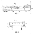
- Figure 2 shows a side elevation view of the unitized equipment floor 20 shown in Figure 1 .
- Figure 2 shows the components of the unitized equipment floor 20 connected together to form the structural support "frame" for the center portion of the rig floor of a typical drilling rig.
- the unitized equipment floor 20 or, if no unitized assembly is used, the individual structural components of the spreader assemblies, must be "pinned" to the side boxes 10 and 11 in multiple locations.
- six pin connection points - designated 35a through 35f - are utilized along each side of the unitized equipment floor 20.
- a total of twelve pin connection points are utilized to connect the unitized equipment floor 20 to the side boxes 10 and 11 of the substructure 5.
- the number of pin connection points may be greater than or less than the twelve connection points shown in Figure 2 .
- the significant forces and stresses imposed on the pins connecting the unitized equipment floor 20 to the side boxes 10 and 11 of the substructure 5 typically require the use of two pins at each of the twelve pin connection points shown in Figure 2 - for a total of twenty-four pins.
- the number of pin connection points may vary according to the size and weight of the unitized equipment floor 20 and, thus, the number of pins may vary accordingly.
- the number of pin connection points and pins used to connect the unitized equipment floor 20 to the side boxes 10 and 11 of the substructure 5 can be substantial.
- the structural connector of the present invention eliminates the pin-type connections of prior art drilling rigs and, thus, substantially reduces the amount of time required to assemble a drilling rig at the drill site.
- FIG 2a shows a front elevation view of the unitized equipment floor 20 shown in Figure 2 .
- mating lugs assemblies 41 have been connected to the setback spreader assembly 22 of the unitized equipment floor 20 (such connection point corresponding to connection point 35f shown in Figure 2 ).
- the mating lugs assemblies 41 can be connected to the setback spreader assembly 22 through any suitable metal-to-metal connection method capable of handling the significant forces and stresses imposed on the mating lugs assemblies 40 and 41.
- the mating lugs assemblies 41 are welded to the setback spreader assembly 22.
- additional mating lugs assemblies 41 can be attached to the unitized equipment floor 20 at each of the connection points designated 35a through 35e in Figure 2 .
- Figure 3 is an enlarged side view of the mating lugs assembly 41 shown in Figure 2a .
- the mating lugs assembly 41 is attached to the setback spreader assembly 22 along the entire length of the connection points a and b shown in Figure 3 .
- the mating lugs assembly 41 is welded in place at connection points a and b.
- Figure 3 shows mating lug 46 and mating lug 47 attached to mating lugs assembly 41, as discussed in more detail below with reference to Figures 3a and 3b.
- Figure 3 also shows the unique "saddle" shape of mating lug 46 and mating lug 47.
- the shape of mating lugs 46 and 47 is shown in more detail in Figure 3b , discussed below.
- FIG 3a is a top view of the mating lugs assembly 41 attached to the setback spreader assembly 22 as shown in Figure 3 .
- mating lugs assembly 41 preferably consists of two metal "plates," mating lug plate 43 and mating lug plate 44, separated by a short distance.
- Mating lug plate 43 and mating lug plate 44 each have two mating lugs, mating lug 46 and mating lug 47, attached to their inside plate surface.
- the structural connector of one embodiment of the present invention utilizes four mating lugs at each mating lugs assembly.
- mating lugs 46 and 47 are welded to the inside surfaces of mating lug plates 43 and 44.
- mating lugs 46 and 47 can be attached to mating lug plates 43 and 44 by any suitable metal-to-metal connection method that is capable of handling the significant forces and stresses imposed on the mating plates and mating lugs.
- the unique shape of the support notch of the mating lugs 46 and 47 may be cut into mating lug plates 43 and 44 in lieu of attaching mating lugs 46 and 47 to the surfaces of mating lug plates 43 and 44. Cutting the unique shape of the support notch of the mating lugs 46 and 47 into mating lug plates 43 and 44 can be used for smaller drilling rigs with lighter equipment floors, as cutting material out of mating lug plates 43 and 44 may reduce the load handling capability of the plates.
- Mating lug 46 and mating lug 47 are specially shaped to achieve the objectives of the present invention.
- mating lugs 46 and 47 each consist of a square or rectangular metal piece 50 with a uniquely shaped support notch 51.
- Support notch 51 is specially shaped to have vertical, or substantially vertical, side walls 52 and 53 and a contoured top surface 54. Additionally, support notch 51 is shaped with tapered guide surfaces 55 and 56 at the entry point of the support notch 51.
- the unique shape of support notch 51 is specially designed to mate with the uniquely shaped fixed support members in accordance with the present invention.
- Mating lug plates 43 and 44 are specifically shaped such that mating lugs 46 and 47 can be attached to the plates at locations that allow for unhindered access to the support notch 51 of both mating lugs 46 and 47.
- mating lug 47 is attached to mating lug plate 44 at a location that is lower than the attachment point for mating lug 46 and closer to setback spreader assembly 22.
- mating lug 46 is attached to mating lug plate 44 at a higher location than the attachment point for mating lug 47 and further from setback spreader assembly 22.
- a second set of mating lugs 46 and 47 is attached to mating lug plate 43 at the same locations.
- this configuration allows mating lugs 46 and 47 on mating lug plates 43 and 44 to mate with the fixed support members of the support plate attached to the side boxes of the substructure to form the structural connector of the present invention.
- support plate 60 of a preferred embodiment of the present invention is shown.
- support plate 60 is attached to side box 11 of the drilling rig substructure 5 (as designated in Figure 1 ).
- Support plate 60 is attached to side box 11 at a location aligned with connection point 35f such that it can mate with the corresponding mating lugs assembly 41 attached to the unitized equipment floor 20 at connection point 35f.
- Support plate 60 can be connected to the side box 11 of the substructure through any suitable metal-to-metal connection method capable of handling the significant forces and stresses imposed on the support plate 60.
- the support plate 60 is welded to the side box 11.
- additional support plates 60 can be attached to side box 11 at locations that are aligned with each of the connection points designated 35a through 35e in Figure 2 such that the support plates 60 can mate with the mating lugs assemblies 41.
- fixed support member 61 and fixed support member 62 are attached to and extend outwardly from both sides of support plate 60.
- Figure 4a is a top view of the support plate 60 connected to side box 11.
- Figure 4a shows fixed support members 61 and 62 extending outwardly from both sides of the support plate 60.
- fixed support members 61 and 62 extend outwardly from the sides of support plate 60 approximately 1-2 inches. The above range of distance is given by way of example only.
- the distance fixed support members 61 and 62 extend out from the sides of support plate 60 can vary significantly depending on several factors, including, but not limited to, the loads imposed on the support plate and fixed support members, the size of the fixed support members themselves, the size of the support plate, and the materials used to make the support members and the support plate.
- the fixed support members 61 and 62 are shown in more detail in Figure 4b .
- the fixed support members 61 and 62 are specially shaped to have vertical, or substantially vertical, side walls 66 and 67 and a contoured top surface 68.
- the shape and size of fixed support members 61 and 62 is specifically designed to mate with the support notch 51 shown in Figure 3b .
- the fixed support members 61 and 62 can be attached to the support plate 60 by cutting a hole in the support plate 60 to correspond to the shape and size of the fixed support members 61 and 62, passing the fixed support members 61 and 62 through such hole, and then welding the fixed support members 61 and 62 in place. It will be appreciated by one of skill in the art that fixed support members 61 and 62 can be attached to support plate 60 by any suitable metal-to-metal connection method that is capable of handling the significant forces and stresses imposed on the support plate and fixed support members.
- support plate 60 is specifically shaped to allow fixed support members 61 and 62 to be attached at locations on the support plate 60 such that they can engage support notches 51 of both mating lugs 46 and 47 to form the structural connector of the present invention.
- fixed support member 62 is attached to support plate 60 at a location that is lower than the attachment point for fixed support member 61 and further away from side box 11.
- fixed support member 61 is attached to support plate 60 at a higher location than the attachment point for fixed support member 62 and closer to side box 11. As discussed in reference to Figures 5 and 5a below, this configuration allows fixed support members 61 and 62 to mate with the mating lugs on the mating lugs assembly to form the structural connector of the present invention.
- the completed structural connector will be described with reference to Figures 5 and 5a .
- the elements of the disclosed structural connector are shown vertically aligned such that the connection can be made up.
- the side boxes of the substructure will be placed on the ground and positioned in such a way that the unitized equipment floor can be lowered into place and connected to the side boxes.
- the mating lugs assembly 41 attached to the setback spreader assembly 22 is aligned above the support plate 60 attached to the side box 11 of the substructure.
- the mating lugs assembly 41 is aligned such that the support notches 51 in mating lugs 46 and 47 attached to mating lug plate 44 can be lowered into a mating position with fixed support members 61 and 62 on one side of the support plate 60.
- the support notches 51 of mating lugs 46 and 47 attached to mating lug plate 43 are mated with fixed support members 61 and 62 on the opposite side of the support plate 60.
- the tapered guide surfaces 55 and 56 of the support notches 51 act as a "guide” that guides the mating lugs 46 and 47 into engagement with the fixed support members 61 and 62.
- the use of tapered guide surfaces 55 and 56 further increases the efficiency with which the structural connector of the present invention can be made up.
- the mating lug plates 43 and 44 of the mating lugs assembly 41 are on either side of the support plate 60 as shown in Figure 5a .
- the ends of fixed support members 61 and 62 extending outwardly on both sides of support plate 60 fit tightly within the corresponding notches 51 of mating lugs 46 and 47 attached to mating plates 43 and 44.
- the structural connector of the preferred embodiment of the present invention comprises a four point connection in which the ends of fixed support member 61 engage the two support notches 51 of the two mating lugs 46 attached to mating lug plates 43 and 44, and the ends of fixed support member 62 engage the two support notches 51 of the two mating lugs 47 attached to mating lug plates 43 and 44.
- the structural connector may utilize two support plates - with each plate having two fixed support members extending therethrough - and a mating lugs assembly consisting of three mating plates.
- the structural connector would comprise an eight point connection in the manner described above with reference to the preferred embodiment.
- the number of support plates and number of mating plates used in another embodiment of the structural connector could be increased to three and four respectively to create an even stronger connection.
- numerous alternative embodiments of the present invention can be made by adding additional support plates and additional mating lug plates to the structural connector to increase the load handling capability of the connection.
- the location of the support plates and the location of the mating lugs assemblies can be reversed, i.e., the support plates can be attached to the unitized equipment floor (instead of the side boxes), and the mating lugs assemblies can be attached to the side boxes.(instead of the unitized equipment floor).
- the contoured tops of the fixed support members would face downward (in the direction of the ground) such that they could mate with upward facing mating lugs - with the opening of the support notch in the mating lugs facing upwardly.
- the result of the mating of the support notches 51 of the mating lugs 46 and 47 with the fixed support members 61 and 62 - as shown in Figure 5a - is a structural connector capable of handling the significant vertical forces imposed on the connection by the weight of the unitized equipment floor and the significant moment imposed on the connection by horizontal forces acting on the connection.
- the ability of the structural connector of the present invention to handle these significant forces and stresses is derived from the uniquely shaped support notches 51 (shown in detail in Figure 3b ) and uniquely shaped fixed support members 61 and 62 (shown in detail in Figure 4b ).
- the vertical load caused by the weight of the unitized equipment floor is spread evenly over the entire contoured tops 68 such that the vertical load can be effectively carried by the fixed support members 61 and 62.
- the structural connector of the present invention is capable of handling high horizontal loads.
- the horizontal load handling capability is attributable to the mating of the vertical, or substantially vertical, side walls 66 and 67 of the fixed support members 61 and 62 with the vertical, or substantially vertical, side walls 52 and 53 of the support notches 51 of the mating lugs 46 and 47.
- the use of vertical, or substantially vertical, side walls allows the horizontal loads imposed on the connection to be carried over a greater surface area.
- the side walls 66 and 67 of the fixed support members 61 and 62 are in contact with the side walls 52 and 53 of the support notches 51 along the entire length of the walls.
- any horizontal forces acting on the connection will be spread out over the entire surface of the walls and, thus, the stresses placed on the connection point by these horizontal forces is reduced. Further, if significant horizontal forces are expected, the length of the side walls 66 and 67 of the fixed support members 61 and 62 and the length of the side walls 52 and 53 of the support notches 51 can be increased to provide an even greater area to handle such forces.
Landscapes
- Engineering & Computer Science (AREA)
- Geology (AREA)
- Life Sciences & Earth Sciences (AREA)
- Mining & Mineral Resources (AREA)
- Physics & Mathematics (AREA)
- Environmental & Geological Engineering (AREA)
- Fluid Mechanics (AREA)
- Mechanical Engineering (AREA)
- General Life Sciences & Earth Sciences (AREA)
- Geochemistry & Mineralogy (AREA)
- Connection Of Plates (AREA)
- Earth Drilling (AREA)
- Joining Of Building Structures In Genera (AREA)
Claims (21)
- Connecteur structurel comprenant :une plaque de support (60) comprenant une pluralité d'éléments de support fixes (61, 62) s'étendant à travers cette dernière, les éléments de support fixes ayant des parois latérales (66, 67) et des sommets profilés (68) ; un ensemble à talons d'accouplement (41) comprenant un couple de plaques à talons d'accouplement (43, 44) et une pluralité de talons d'accouplement (46, 47) attachés à chaque plaque à talons d'accouplement, chaque talon d'accouplement ayant une encoche de support (51) en son sein qui est formée et dimensionnée pour s'accoupler avec l'élément de support fixe, dans lequel l'encoche de support de chaque talon d'accouplement comprend des surfaces de guidage évasées (55, 56) au niveau du point d'entrée de l'encoche de support, des parois latérales (52, 53) et un sommet profilé (54).
- Connecteur structurel selon la revendication 1 dans lequel la pluralité d'éléments de support fixes (61, 62) s'étend extérieurement à partir des deux côtés de la plaque de support (60), et les parois latérales (66, 67) de chaque élément de support fixe (61, 62) peuvent être sensiblement verticales.
- Connecteur structurel selon la revendication 1 ou la revendication 2, dans lequel l'encoche de support (51) de chaque talon d'accouplement (46, 47) a des parois latérales verticales (52, 53).
- Connecteur structurel selon l'une quelconque des revendications précédentes, dans lequel les talons d'accouplement (46, 47) sont soudés aux plaques à talons d'accouplement (43, 44), ou dans lequel les talons d'accouplement sont formés en découpant la forme de l'encoche de support dans les plaques à talons d'accouplement.
- Connecteur structurel selon l'une quelconque des revendications précédentes, dans lequel une charge verticale sur le connecteur structurel est portée par l'accouplement des sommets profilés des encoches de support avec les sommets profilés des éléments de support fixes, et/ou une charge horizontale sur le connecteur structurel est portée par l'accouplement des parois latérales des encoches de support des talons d'accouplement avec les parois latérales des éléments de support fixes.
- Connecteur structurel selon la revendication 1 dans lequel les parois latérales de chacun du ou des plusieurs éléments de support fixes sont sensiblement verticales, et/ou les parois latérales des encoches de support de chacun du ou des plusieurs talons d'accouplement sont sensiblement verticales.
- Connecteur structurel selon la revendication 1 ou la revendication 6, dans lequel les talons d'accouplement sont soudés aux plaques à talons d'accouplement, ou les talons d'accouplement sont formés en découpant la forme de l'encoche de support dans les plaques à talons d'accouplement.
- Connecteur structurel selon l'une quelconque des revendications précédentes 1, 6 ou 7, dans lequel une charge verticale sur le connecteur structurel est portée par l'accouplement des sommets profilés des encoches de support avec les sommets profilés du ou des plusieurs éléments de support fixes et/ou une charge horizontale sur le connecteur structurel est portée par l'accouplement des parois latérales des encoches de support avec les parois latérales du ou des plusieurs éléments de support fixes.
- Connecteur structurel selon l'une quelconque des revendications 1 ou 6 à 8, dans lequel le connecteur structurel est utilisé pour relier un plancher d'équipement par éléments préfabriqués d'un derrick à l'infrastructure du derrick.
- Connecteur structurel selon l'une quelconque des revendications 1 ou 6 à 9, dans lequel il y a une pluralité de plaques de support, chacune ayant une pluralité d'éléments de support fixes s'étendant à travers cette dernière, et l'ensemble à talons d'accouplement comprend une pluralité de plaques à talons d'accouplement et une pluralité de talons d'accouplement attachés à chaque plaque à talons d'accouplement.
- Procédé de connexion de composants structurels comprenant :le fait de munir un ou plusieurs premiers composants structurels, chacun d'une ou plusieurs plaques de support (60) attachées à ces derniers ; le fait de munir chaque plaque de support d'une pluralité d'éléments de support fixes (61, 62) s'étendant à travers celle-ci, chaque élément de support fixe comprenant des parois latérales (66, 67) et un sommet profilé (68) ;le fait de munir un ou plusieurs seconds composants structurels, chacun d'un ou plusieurs ensembles à talons d'accouplement (41) attachés à ces derniers, chaque ensemble à talons d'accouplement comprenant une pluralité de plaques à talons d'accouplement (43, 44) et une pluralité de talons d'accouplement (46, 47) attachés à chaque plaque à talons d'accouplement ;le fait de munir chaque talon d'accouplement d'une encoche de support, l'encoche de support (51) comprenant des surfaces de guidage évasées (55, 56) au niveau du point d'entrée de l'encoche de support, des parois latérales (52, 53) et un sommet profilé (54) ;le positionnement du premier composant structurel et du second composant structurel pour connexion ;l'alignement des talons d'accouplement des ensembles à talons d'accouplement avec les éléments de support fixes des plaques de support ; le guidage des éléments de support fixes (61, 62) des plaques de support en prise avec les encoches de support (51) des talons d'accouplement en utilisant les surfaces de guidage évasées des encoches de support.
- Procédé selon la revendication 11, comprenant en outre le fait de munir les éléments de support fixes de parois latérales sensiblement verticales (66, 67).
- Procédé selon la revendication 11 ou la revendication 12, comprenant en outre le soudage des talons d'accouplement aux plaques à talons d'accouplement, et/ou la découpe de la forme des encoches de support dans les plaques à talons d'accouplement.
- Procédé selon la revendication 11, dans lequel les composants structurels servent à un derrick et dans lequel :les premiers composants structurels comprennent :une première boîte latérale (10) et une seconde boîte latérale (11)dans lequel le second composant structurel prévu est un plancher d'équipement (20).
- Procédé selon la revendication 14, comprenant en outre l'assemblage de composants du plancher d'équipement pour former un plancher d'équipement par éléments préfabriqués.
- Procédé selon la revendication 14 ou la revendication 15 comprenant en outre le fait de munir les éléments de support fixes de parois latérales sensiblement verticales.
- Procédé selon l'une quelconque des revendications 14 à 16, comprenant en outre le soudage des talons d'accouplement aux plaques à talons d'accouplement, et/ou la découpe de la forme des encoches de support dans les plaques à talons d'accouplement.
- Procédé selon la revendication 11, dans lequel les composants structurels servent à un derrick et dans lequel :le premier composant structurel prévu est un plancher d'équipement (20) ;les seconds composants structurels comprennent :une première boîte latérale (10) ; etune seconde boîte latérale (11).
- Procédé selon la revendication 18, comprenant en outre l'assemblage de composants du plancher d'équipement pour former un plancher d'équipement par éléments préfabriqués.
- Procédé selon la revendication 17 ou la revendication 18, comprenant en outre le fait de munir les éléments de support fixes de parois latérales sensiblement verticales.
- Procédé selon l'une quelconque des revendications 18 à 20, comprenant en outre le soudage des talons d'accouplement aux plaques à talons d'accouplement, et/ou la découpe de la forme des encoches de support dans les plaques à talons d'accouplement.
Applications Claiming Priority (3)
| Application Number | Priority Date | Filing Date | Title |
|---|---|---|---|
| US46388203P | 2003-04-17 | 2003-04-17 | |
| US10/822,353 US7155873B2 (en) | 2003-04-17 | 2004-04-12 | Structural connector for a drilling rig substructure |
| PCT/US2004/011610 WO2004094762A2 (fr) | 2003-04-17 | 2004-04-16 | Connecteur de structure pour infrastructure d'installation de forage |
Publications (4)
| Publication Number | Publication Date |
|---|---|
| EP1620610A2 EP1620610A2 (fr) | 2006-02-01 |
| EP1620610A4 EP1620610A4 (fr) | 2011-07-06 |
| EP1620610B1 true EP1620610B1 (fr) | 2015-04-15 |
| EP1620610B8 EP1620610B8 (fr) | 2015-05-27 |
Family
ID=33162394
Family Applications (1)
| Application Number | Title | Priority Date | Filing Date |
|---|---|---|---|
| EP04759879.2A Expired - Lifetime EP1620610B8 (fr) | 2003-04-17 | 2004-04-16 | Connecteur de structure pour infrastructure d'installation de forage |
Country Status (7)
| Country | Link |
|---|---|
| US (2) | US7155873B2 (fr) |
| EP (1) | EP1620610B8 (fr) |
| BR (1) | BRPI0409397B1 (fr) |
| CA (1) | CA2522569C (fr) |
| DK (1) | DK1620610T3 (fr) |
| MX (1) | MXPA05011219A (fr) |
| WO (1) | WO2004094762A2 (fr) |
Families Citing this family (15)
| Publication number | Priority date | Publication date | Assignee | Title |
|---|---|---|---|---|
| US8549815B2 (en) * | 2008-02-29 | 2013-10-08 | National Oilwell Varco L.P. | Drilling rig masts and methods of assembly and erecting masts |
| US8813436B2 (en) | 2008-02-29 | 2014-08-26 | National Oilwell Varco, L.P. | Pinned structural connection using a pin and plug arrangement |
| US8047303B2 (en) * | 2008-02-29 | 2011-11-01 | National Oilwell Varco L.P. | Drilling rig drawworks installation |
| US8468753B2 (en) * | 2008-02-29 | 2013-06-25 | National Oilwell Varco L.P. | Drilling rigs and erection methods |
| US8250816B2 (en) * | 2008-02-29 | 2012-08-28 | National Oilwell Varco L.P. | Drilling rig structure installation and methods |
| US9091125B2 (en) | 2012-01-16 | 2015-07-28 | National Oilwell Varco, L.P. | Collapsible substructure for a mobile drilling rig |
| WO2014182991A1 (fr) | 2013-05-10 | 2014-11-13 | Devin International, Inc. | Système et procédé de transfert d'appareil de forage |
| EA036726B1 (ru) | 2014-07-14 | 2020-12-11 | Дреко Энерджи Сервисез Юлс | Передвижная буровая установка |
| US9988807B2 (en) | 2016-02-24 | 2018-06-05 | National Oilwell Varco, L.P. | Drilling rig with self-elevating drill floor |
| WO2017155950A1 (fr) | 2016-03-07 | 2017-09-14 | National Oilwell Varco, L.P. | Remorque cave avant-puits de bloc obturateur de puits multipuits |
| US9970211B2 (en) | 2016-05-02 | 2018-05-15 | Dreco Energy Services Ulc | Guide rails for mobile drilling rig |
| US10293854B2 (en) | 2016-10-05 | 2019-05-21 | Dreco Energy Services Ulc | Movable rig and steering system |
| US11454067B2 (en) | 2018-08-06 | 2022-09-27 | Nov Canada Ulc | Drill floor support structures |
| US11603723B2 (en) | 2019-08-30 | 2023-03-14 | Nov Canada Ulc | Cuttings processing unit |
| CN112282659A (zh) * | 2020-10-14 | 2021-01-29 | 山东科瑞油气装备有限公司 | 一种销孔与端面组合连接式井架的制作方法 |
Citations (2)
| Publication number | Priority date | Publication date | Assignee | Title |
|---|---|---|---|---|
| FR2359302A1 (fr) * | 1976-07-21 | 1978-02-17 | Murphy Thomas | Elements structuraux d'interconnexion |
| WO2003021061A1 (fr) * | 2001-08-30 | 2003-03-13 | Simmons Robert J | Pieces de structure de cadre de construction resistante aux moments |
Family Cites Families (26)
| Publication number | Priority date | Publication date | Assignee | Title |
|---|---|---|---|---|
| US656456A (en) * | 1899-11-14 | 1900-08-21 | Hiram H Hirsch | Bedstead-fastener. |
| US691427A (en) * | 1901-03-14 | 1902-01-21 | George Williams | Hook and lock for iron bedsteads. |
| US744194A (en) * | 1903-05-25 | 1903-11-17 | William Harrison | Knockdown scaffolding. |
| US792366A (en) * | 1904-01-06 | 1905-06-13 | Alfred Taylor | Bedstead construction. |
| US795947A (en) * | 1904-08-06 | 1905-08-01 | Frank B Upton | Metallic bed. |
| US932233A (en) * | 1909-02-23 | 1909-08-24 | John M Adams | Joint for metal beds. |
| US1090955A (en) * | 1913-10-18 | 1914-03-24 | Patrick Henry Yorke | Metallic derrick. |
| US2962170A (en) * | 1958-07-01 | 1960-11-29 | John H Best & Sons | Storage racks |
| US3150617A (en) * | 1961-10-18 | 1964-09-29 | Edwin D Phillips | Interlocking joint |
| US4729484A (en) * | 1983-10-14 | 1988-03-08 | Interlake, Corporation | Pallet rack construction |
| US4831795A (en) * | 1985-07-10 | 1989-05-23 | Sorokan Ronald S | Drilling derrick assembly |
| DE3914618A1 (de) * | 1989-05-03 | 1990-11-08 | Bulldog Beratung | Verbindungselement fuer (holz-)balken |
| JP2879392B2 (ja) * | 1992-04-17 | 1999-04-05 | カトウ産業株式会社 | 木造建築用軸組構造及び軸組具 |
| US5438811A (en) * | 1993-03-22 | 1995-08-08 | Shigeo Goya | Jointing metal fixture for construction |
| JP3355560B2 (ja) * | 1994-04-27 | 2002-12-09 | 株式会社建築資料研究社 | 梁乃至桁接合用具 |
| US5845453A (en) * | 1995-09-19 | 1998-12-08 | Kuretec Limited Company | Jointing metal fitting for buildings |
| US5769249A (en) * | 1996-12-16 | 1998-06-23 | Unarco Material Handling, Inc. | Storage rack beam having rolled, intermediate section with upturned, deck-supporting edge and with inclined, indicia-receiving surface |
| US5975318A (en) * | 1998-02-13 | 1999-11-02 | Display Technologies, Inc. | Display shelf assembly and bracket useful therein |
| GB9927012D0 (en) * | 1999-11-16 | 2000-01-12 | Steel Construction The | Connecting apparatus |
| US6820758B2 (en) * | 2001-04-20 | 2004-11-23 | North American Steel Equipment Company Ltd. | Lock for knock-down storage rack |
| NL1018663C2 (nl) * | 2001-07-30 | 2003-02-03 | Hugo Casper Johan De Rijk | Klemverbinding tussen een staanderelement en een liggerelement. |
| US6925666B2 (en) * | 2001-11-05 | 2005-08-09 | Lawrence Harrow | Easy to assemble bed base, two-component connector and kit |
| US6802169B2 (en) * | 2002-03-18 | 2004-10-12 | Robert J. Simmons | Building frame structure |
| US6920990B2 (en) * | 2003-01-21 | 2005-07-26 | Steel King Industries, Inc. | Column protector |
| US7128225B2 (en) * | 2003-11-17 | 2006-10-31 | Edsal Manufacturing Co., Inc. | Cargo rack |
| US20060144809A1 (en) * | 2004-12-30 | 2006-07-06 | Edsal Manufacturing Co., Inc. | Shelving connector |
-
2004
- 2004-04-12 US US10/822,353 patent/US7155873B2/en not_active Expired - Lifetime
- 2004-04-16 DK DK04759879.2T patent/DK1620610T3/en active
- 2004-04-16 CA CA2522569A patent/CA2522569C/fr not_active Expired - Fee Related
- 2004-04-16 WO PCT/US2004/011610 patent/WO2004094762A2/fr not_active Ceased
- 2004-04-16 BR BRPI0409397A patent/BRPI0409397B1/pt not_active IP Right Cessation
- 2004-04-16 EP EP04759879.2A patent/EP1620610B8/fr not_active Expired - Lifetime
- 2004-04-16 MX MXPA05011219A patent/MXPA05011219A/es active IP Right Grant
-
2006
- 2006-09-19 US US11/523,316 patent/US20070011984A1/en not_active Abandoned
Patent Citations (2)
| Publication number | Priority date | Publication date | Assignee | Title |
|---|---|---|---|---|
| FR2359302A1 (fr) * | 1976-07-21 | 1978-02-17 | Murphy Thomas | Elements structuraux d'interconnexion |
| WO2003021061A1 (fr) * | 2001-08-30 | 2003-03-13 | Simmons Robert J | Pieces de structure de cadre de construction resistante aux moments |
Also Published As
| Publication number | Publication date |
|---|---|
| WO2004094762A2 (fr) | 2004-11-04 |
| EP1620610A4 (fr) | 2011-07-06 |
| EP1620610B8 (fr) | 2015-05-27 |
| DK1620610T3 (en) | 2015-06-15 |
| US20040206041A1 (en) | 2004-10-21 |
| CA2522569C (fr) | 2010-06-15 |
| WO2004094762A3 (fr) | 2005-06-30 |
| US7155873B2 (en) | 2007-01-02 |
| EP1620610A2 (fr) | 2006-02-01 |
| CA2522569A1 (fr) | 2004-11-04 |
| US20070011984A1 (en) | 2007-01-18 |
| BRPI0409397A (pt) | 2006-04-18 |
| BRPI0409397B1 (pt) | 2015-09-15 |
| MXPA05011219A (es) | 2006-07-06 |
Similar Documents
| Publication | Publication Date | Title |
|---|---|---|
| EP1620610B1 (fr) | Connecteur de structure pour infrastructure d'installation de forage | |
| CA2523505C (fr) | Dispositif de forage a deplacement rapide | |
| US8596016B1 (en) | Method and apparatus for constructing drilling platforms without driven pins | |
| US8640767B2 (en) | Push / pull system and support structure for snubbing unit on a rig floor | |
| CA2835612C (fr) | Raccord structural cheville utilisant un ensemble a cheville et connecteur male | |
| US10465377B2 (en) | Drilling rig with self-elevating drill floor | |
| US9464488B2 (en) | Performing simultaneous operations on multiple wellbore locations using a single mobile drilling rig | |
| EP2337922B1 (fr) | Installation de forage et son procédé de montage | |
| DE102008038456A1 (de) | Bohranlage | |
| US9512676B2 (en) | Mast leg pulley | |
| CA2966021A1 (fr) | Appareil de traitement d'un bloc d'obturation de puits | |
| US20240218750A1 (en) | Drilling rig system | |
| JP3717910B2 (ja) | ヘリコプタによる鉄塔組立工法 | |
| US11608684B2 (en) | Mast for drilling machines | |
| WO2017034400A2 (fr) | Système d'installation de forage modulaire | |
| EP3653833A1 (fr) | Système d'installation de forage modulaire | |
| CN104895572A (zh) | 山体垂直线掘井机 |
Legal Events
| Date | Code | Title | Description |
|---|---|---|---|
| PUAI | Public reference made under article 153(3) epc to a published international application that has entered the european phase |
Free format text: ORIGINAL CODE: 0009012 |
|
| 17P | Request for examination filed |
Effective date: 20051109 |
|
| AK | Designated contracting states |
Kind code of ref document: A2 Designated state(s): AT BE BG CH CY CZ DE DK EE ES FI FR GB GR HU IE IT LI LU MC NL PL PT RO SE SI SK TR |
|
| AX | Request for extension of the european patent |
Extension state: AL HR LT LV MK |
|
| DAX | Request for extension of the european patent (deleted) | ||
| A4 | Supplementary search report drawn up and despatched |
Effective date: 20110606 |
|
| RIC1 | Information provided on ipc code assigned before grant |
Ipc: E04B 1/38 20060101AFI20050707BHEP Ipc: E21B 15/00 20060101ALI20110527BHEP |
|
| 17Q | First examination report despatched |
Effective date: 20121205 |
|
| GRAP | Despatch of communication of intention to grant a patent |
Free format text: ORIGINAL CODE: EPIDOSNIGR1 |
|
| INTG | Intention to grant announced |
Effective date: 20141023 |
|
| GRAS | Grant fee paid |
Free format text: ORIGINAL CODE: EPIDOSNIGR3 |
|
| GRAA | (expected) grant |
Free format text: ORIGINAL CODE: 0009210 |
|
| AK | Designated contracting states |
Kind code of ref document: B1 Designated state(s): AT BE BG CH CY CZ DE DK EE ES FI FR GB GR HU IE IT LI LU MC NL PL PT RO SE SI SK TR |
|
| REG | Reference to a national code |
Ref country code: GB Ref legal event code: FG4D Ref country code: CH Ref legal event code: EP |
|
| REG | Reference to a national code |
Ref country code: DE Ref legal event code: R082 Ref document number: 602004047007 Country of ref document: DE Representative=s name: WUESTHOFF & WUESTHOFF, PATENTANWAELTE PARTG MB, DE |
|
| REG | Reference to a national code |
Ref country code: IE Ref legal event code: FG4D |
|
| RAP2 | Party data changed (patent owner data changed or rights of a patent transferred) |
Owner name: NATIONAL OILWELL VARCO, L.P. |
|
| REG | Reference to a national code |
Ref country code: AT Ref legal event code: REF Ref document number: 722080 Country of ref document: AT Kind code of ref document: T Effective date: 20150515 |
|
| REG | Reference to a national code |
Ref country code: DE Ref legal event code: R096 Ref document number: 602004047007 Country of ref document: DE Effective date: 20150528 |
|
| REG | Reference to a national code |
Ref country code: DK Ref legal event code: T3 Effective date: 20150608 |
|
| REG | Reference to a national code |
Ref country code: NL Ref legal event code: T3 |
|
| REG | Reference to a national code |
Ref country code: AT Ref legal event code: MK05 Ref document number: 722080 Country of ref document: AT Kind code of ref document: T Effective date: 20150415 |
|
| PG25 | Lapsed in a contracting state [announced via postgrant information from national office to epo] |
Ref country code: ES Free format text: LAPSE BECAUSE OF FAILURE TO SUBMIT A TRANSLATION OF THE DESCRIPTION OR TO PAY THE FEE WITHIN THE PRESCRIBED TIME-LIMIT Effective date: 20150415 Ref country code: PT Free format text: LAPSE BECAUSE OF FAILURE TO SUBMIT A TRANSLATION OF THE DESCRIPTION OR TO PAY THE FEE WITHIN THE PRESCRIBED TIME-LIMIT Effective date: 20150817 Ref country code: FI Free format text: LAPSE BECAUSE OF FAILURE TO SUBMIT A TRANSLATION OF THE DESCRIPTION OR TO PAY THE FEE WITHIN THE PRESCRIBED TIME-LIMIT Effective date: 20150415 |
|
| REG | Reference to a national code |
Ref country code: DE Ref legal event code: R119 Ref document number: 602004047007 Country of ref document: DE |
|
| PG25 | Lapsed in a contracting state [announced via postgrant information from national office to epo] |
Ref country code: GR Free format text: LAPSE BECAUSE OF FAILURE TO SUBMIT A TRANSLATION OF THE DESCRIPTION OR TO PAY THE FEE WITHIN THE PRESCRIBED TIME-LIMIT Effective date: 20150716 Ref country code: AT Free format text: LAPSE BECAUSE OF FAILURE TO SUBMIT A TRANSLATION OF THE DESCRIPTION OR TO PAY THE FEE WITHIN THE PRESCRIBED TIME-LIMIT Effective date: 20150415 |
|
| REG | Reference to a national code |
Ref country code: CH Ref legal event code: PL |
|
| REG | Reference to a national code |
Ref country code: IE Ref legal event code: MM4A |
|
| PG25 | Lapsed in a contracting state [announced via postgrant information from national office to epo] |
Ref country code: LI Free format text: LAPSE BECAUSE OF NON-PAYMENT OF DUE FEES Effective date: 20150430 Ref country code: CH Free format text: LAPSE BECAUSE OF NON-PAYMENT OF DUE FEES Effective date: 20150430 Ref country code: IT Free format text: LAPSE BECAUSE OF FAILURE TO SUBMIT A TRANSLATION OF THE DESCRIPTION OR TO PAY THE FEE WITHIN THE PRESCRIBED TIME-LIMIT Effective date: 20150415 Ref country code: EE Free format text: LAPSE BECAUSE OF FAILURE TO SUBMIT A TRANSLATION OF THE DESCRIPTION OR TO PAY THE FEE WITHIN THE PRESCRIBED TIME-LIMIT Effective date: 20150415 Ref country code: MC Free format text: LAPSE BECAUSE OF FAILURE TO SUBMIT A TRANSLATION OF THE DESCRIPTION OR TO PAY THE FEE WITHIN THE PRESCRIBED TIME-LIMIT Effective date: 20150415 Ref country code: DE Free format text: LAPSE BECAUSE OF NON-PAYMENT OF DUE FEES Effective date: 20151103 |
|
| PLBE | No opposition filed within time limit |
Free format text: ORIGINAL CODE: 0009261 |
|
| STAA | Information on the status of an ep patent application or granted ep patent |
Free format text: STATUS: NO OPPOSITION FILED WITHIN TIME LIMIT |
|
| PG25 | Lapsed in a contracting state [announced via postgrant information from national office to epo] |
Ref country code: SK Free format text: LAPSE BECAUSE OF FAILURE TO SUBMIT A TRANSLATION OF THE DESCRIPTION OR TO PAY THE FEE WITHIN THE PRESCRIBED TIME-LIMIT Effective date: 20150415 Ref country code: PL Free format text: LAPSE BECAUSE OF FAILURE TO SUBMIT A TRANSLATION OF THE DESCRIPTION OR TO PAY THE FEE WITHIN THE PRESCRIBED TIME-LIMIT Effective date: 20150415 Ref country code: RO Free format text: LAPSE BECAUSE OF NON-PAYMENT OF DUE FEES Effective date: 20150415 Ref country code: CZ Free format text: LAPSE BECAUSE OF FAILURE TO SUBMIT A TRANSLATION OF THE DESCRIPTION OR TO PAY THE FEE WITHIN THE PRESCRIBED TIME-LIMIT Effective date: 20150415 |
|
| REG | Reference to a national code |
Ref country code: FR Ref legal event code: ST Effective date: 20160205 |
|
| 26N | No opposition filed |
Effective date: 20160118 |
|
| PG25 | Lapsed in a contracting state [announced via postgrant information from national office to epo] |
Ref country code: IE Free format text: LAPSE BECAUSE OF NON-PAYMENT OF DUE FEES Effective date: 20150416 |
|
| PG25 | Lapsed in a contracting state [announced via postgrant information from national office to epo] |
Ref country code: FR Free format text: LAPSE BECAUSE OF NON-PAYMENT OF DUE FEES Effective date: 20150615 Ref country code: SI Free format text: LAPSE BECAUSE OF FAILURE TO SUBMIT A TRANSLATION OF THE DESCRIPTION OR TO PAY THE FEE WITHIN THE PRESCRIBED TIME-LIMIT Effective date: 20150415 |
|
| PG25 | Lapsed in a contracting state [announced via postgrant information from national office to epo] |
Ref country code: BE Free format text: LAPSE BECAUSE OF FAILURE TO SUBMIT A TRANSLATION OF THE DESCRIPTION OR TO PAY THE FEE WITHIN THE PRESCRIBED TIME-LIMIT Effective date: 20150415 |
|
| PG25 | Lapsed in a contracting state [announced via postgrant information from national office to epo] |
Ref country code: HU Free format text: LAPSE BECAUSE OF FAILURE TO SUBMIT A TRANSLATION OF THE DESCRIPTION OR TO PAY THE FEE WITHIN THE PRESCRIBED TIME-LIMIT; INVALID AB INITIO Effective date: 20040416 Ref country code: BG Free format text: LAPSE BECAUSE OF FAILURE TO SUBMIT A TRANSLATION OF THE DESCRIPTION OR TO PAY THE FEE WITHIN THE PRESCRIBED TIME-LIMIT Effective date: 20150415 |
|
| PG25 | Lapsed in a contracting state [announced via postgrant information from national office to epo] |
Ref country code: SE Free format text: LAPSE BECAUSE OF FAILURE TO SUBMIT A TRANSLATION OF THE DESCRIPTION OR TO PAY THE FEE WITHIN THE PRESCRIBED TIME-LIMIT Effective date: 20150415 Ref country code: CY Free format text: LAPSE BECAUSE OF FAILURE TO SUBMIT A TRANSLATION OF THE DESCRIPTION OR TO PAY THE FEE WITHIN THE PRESCRIBED TIME-LIMIT Effective date: 20150415 |
|
| PG25 | Lapsed in a contracting state [announced via postgrant information from national office to epo] |
Ref country code: TR Free format text: LAPSE BECAUSE OF FAILURE TO SUBMIT A TRANSLATION OF THE DESCRIPTION OR TO PAY THE FEE WITHIN THE PRESCRIBED TIME-LIMIT Effective date: 20150415 |
|
| PG25 | Lapsed in a contracting state [announced via postgrant information from national office to epo] |
Ref country code: LU Free format text: LAPSE BECAUSE OF NON-PAYMENT OF DUE FEES Effective date: 20150416 |
|
| PGFP | Annual fee paid to national office [announced via postgrant information from national office to epo] |
Ref country code: NL Payment date: 20190412 Year of fee payment: 16 |
|
| PGFP | Annual fee paid to national office [announced via postgrant information from national office to epo] |
Ref country code: DK Payment date: 20190410 Year of fee payment: 16 |
|
| PGFP | Annual fee paid to national office [announced via postgrant information from national office to epo] |
Ref country code: GB Payment date: 20190410 Year of fee payment: 16 |
|
| REG | Reference to a national code |
Ref country code: DK Ref legal event code: EBP Effective date: 20200430 |
|
| REG | Reference to a national code |
Ref country code: NL Ref legal event code: MM Effective date: 20200501 |
|
| GBPC | Gb: european patent ceased through non-payment of renewal fee |
Effective date: 20200416 |
|
| PG25 | Lapsed in a contracting state [announced via postgrant information from national office to epo] |
Ref country code: NL Free format text: LAPSE BECAUSE OF NON-PAYMENT OF DUE FEES Effective date: 20200501 |
|
| PG25 | Lapsed in a contracting state [announced via postgrant information from national office to epo] |
Ref country code: DK Free format text: LAPSE BECAUSE OF NON-PAYMENT OF DUE FEES Effective date: 20200430 Ref country code: GB Free format text: LAPSE BECAUSE OF NON-PAYMENT OF DUE FEES Effective date: 20200416 |