EP1620611B1 - Festellvorrichtung für eine verfahrbare wand - Google Patents
Festellvorrichtung für eine verfahrbare wand Download PDFInfo
- Publication number
- EP1620611B1 EP1620611B1 EP04729071A EP04729071A EP1620611B1 EP 1620611 B1 EP1620611 B1 EP 1620611B1 EP 04729071 A EP04729071 A EP 04729071A EP 04729071 A EP04729071 A EP 04729071A EP 1620611 B1 EP1620611 B1 EP 1620611B1
- Authority
- EP
- European Patent Office
- Prior art keywords
- hold
- open
- wall
- rotary knob
- open device
- Prior art date
- Legal status (The legal status is an assumption and is not a legal conclusion. Google has not performed a legal analysis and makes no representation as to the accuracy of the status listed.)
- Expired - Lifetime
Links
Images
Classifications
-
- E—FIXED CONSTRUCTIONS
- E05—LOCKS; KEYS; WINDOW OR DOOR FITTINGS; SAFES
- E05B—LOCKS; ACCESSORIES THEREFOR; HANDCUFFS
- E05B65/00—Locks or fastenings for special use
- E05B65/08—Locks or fastenings for special use for sliding wings
- E05B65/087—Locks or fastenings for special use for sliding wings the bolts sliding parallel to the wings
-
- E—FIXED CONSTRUCTIONS
- E05—LOCKS; KEYS; WINDOW OR DOOR FITTINGS; SAFES
- E05C—BOLTS OR FASTENING DEVICES FOR WINGS, SPECIALLY FOR DOORS OR WINDOWS
- E05C1/00—Fastening devices with bolts moving rectilinearly
- E05C1/02—Fastening devices with bolts moving rectilinearly without latching action
- E05C1/06—Fastening devices with bolts moving rectilinearly without latching action with operating handle or equivalent member moving otherwise than rigidly with the bolt
-
- Y—GENERAL TAGGING OF NEW TECHNOLOGICAL DEVELOPMENTS; GENERAL TAGGING OF CROSS-SECTIONAL TECHNOLOGIES SPANNING OVER SEVERAL SECTIONS OF THE IPC; TECHNICAL SUBJECTS COVERED BY FORMER USPC CROSS-REFERENCE ART COLLECTIONS [XRACs] AND DIGESTS
- Y10—TECHNICAL SUBJECTS COVERED BY FORMER USPC
- Y10S—TECHNICAL SUBJECTS COVERED BY FORMER USPC CROSS-REFERENCE ART COLLECTIONS [XRACs] AND DIGESTS
- Y10S292/00—Closure fasteners
- Y10S292/46—Sliding door fasteners
-
- Y—GENERAL TAGGING OF NEW TECHNOLOGICAL DEVELOPMENTS; GENERAL TAGGING OF CROSS-SECTIONAL TECHNOLOGIES SPANNING OVER SEVERAL SECTIONS OF THE IPC; TECHNICAL SUBJECTS COVERED BY FORMER USPC CROSS-REFERENCE ART COLLECTIONS [XRACs] AND DIGESTS
- Y10—TECHNICAL SUBJECTS COVERED BY FORMER USPC
- Y10T—TECHNICAL SUBJECTS COVERED BY FORMER US CLASSIFICATION
- Y10T292/00—Closure fasteners
- Y10T292/08—Bolts
- Y10T292/096—Sliding
- Y10T292/1014—Operating means
- Y10T292/1015—Link and lever
Definitions
- the invention relates to a locking device for a movable wall, with a locking element which can be brought into its operative position via a manually operable actuator.
- Such locking devices are required for manually movable walls to set the walls in a particular position.
- Known locking devices include a slider which is guided in a slot provided in the wall and which, when actuated, brings a locking element connected to the slider into its operative position (for example known from document US-A-5 394 648).
- Such a locking device has the disadvantage that the slide must be taken with play in the slot and that can thereby deposit dirt and other impurities in the slot and under the slider, which affect the function of the locking device.
- the actuator is designed as a knob whose rotational movement is convertible into a longitudinal movement for the locking element, on the one hand, the arrangement of a slot in the wall superfluous, on the other hand can be completely dispensed with the slide.
- the locking device according to the invention is less susceptible to dirt and other contaminants.
- the knob is arranged in a surrounding the knob with a small clearance recess in the wall. Characterized in that the knob almost completely fills the wall provided in the opening, the ingress of dirt can be effectively prevented, so that over a long time a secure operation of the locking device according to the invention can be ensured.
- the knob is provided according to an advantageous development on its peripheral surface with a knurling.
- the knob is provided on its side facing the wall with a stub axle to its rotatable mounting and eccentrically to it with an eccentric pin. This allows a secure mounting of the knob in the wall while ensuring a reliable connection with the locking element.
- the eccentric pin engages advantageously in a scenery, which is connected to the locking element. Due to this measure, a good and safe conversion of the rotational movement of the rotary knob is achieved in a longitudinal movement of the locking element.
- the eccentric pin is guided in a circular path arranged in the wall, whose ends serve as a stop for the rotary movement of the rotary knob.
- the end positions the rotational movement and thus the two end positions of the locking element are reliably defined.
- the circular path is preferably formed as a quarter circle in order to achieve an extension of the locking element with the smallest possible angle of rotation.
- the locking element is designed as a latching pin. This allows a simple production of the locking element.
- the locking element is guided in a carrier in its direction of displacement, wherein the carrier is slidably held and lockable on a rail arranged in the wall.
- a locking device according to the invention is shown, which is arranged on a preferably movable by hand wall.
- the (not shown) wall is in its lower part in a profile 1, which is provided in the illustrated embodiment of two profile half-shells with slightly curved outer sides (see Figure 2).
- a circular recess 2 is provided, in which a knob 3 is mounted.
- the recess 2 encloses the knob 3 with a small clearance, so that the ingress of dirt or dust in the gap between the recess 2 and the knob 3 can be largely prevented.
- the knob 3 is provided on its outer periphery with a knurling 4 to allow safe operation of the knob 3.
- the knob 3 is in operative connection with a locking element 5 designed as a latching pin, so that the locking element 5 can be extended or retracted by an actuation of the rotary knob 3.
- the knob 3 is provided on its inside with a central stub axle 6, which allows a rotatable mounting of the knob 3 in the profile 1.
- the knob 3 with the stub axle 6 and the eccentric pin 7 can be made as a one-piece component, for example by injection molding.
- the eccentric pin 7 engages in a slot 8, which receives the eccentric pin 7 in a slot 9.
- the backdrop 8 itself is connected to the locking element 5, for example via a screw connection.
- the locking element 5 is guided in its direction of displacement in a carrier 10, which is held displaceable and fixable in a provided in the profile 1 rail 11.
- a circular path formed as a quarter circle 12 is further provided by which the eccentric pin 7 extends therethrough.
- the ends of the circular path 12 serve as a stop and thus limit the rotational movement of the rotary knob 3 and thus the displacement of the locking element. 5
Landscapes
- Mechanical Engineering (AREA)
- Engineering & Computer Science (AREA)
- Snaps, Bayonet Connections, Set Pins, And Snap Rings (AREA)
- Mechanical Control Devices (AREA)
- Connection Of Plates (AREA)
- Transmission Devices (AREA)
- Casings For Electric Apparatus (AREA)
- Clamps And Clips (AREA)
- Lock And Its Accessories (AREA)
- Ventilation (AREA)
- Automatic Analysis And Handling Materials Therefor (AREA)
- Investigating Or Analysing Materials By The Use Of Chemical Reactions (AREA)
- Processing Of Solid Wastes (AREA)
- Power-Operated Mechanisms For Wings (AREA)
- Supports Or Holders For Household Use (AREA)
Description
- Die Erfindung betrifft eine Feststellvorrichtung für eine verfahrbare Wand, mit einem Feststellelement, das über ein von Hand betätigbares Stellglied in seine Wirkstellung bringbar ist.
- Solche Feststellvorrichtungen sind bei von Hand verfahrbaren Wänden erforderlich, um die Wände in einer bestimmten Position festzulegen. Bekannte Feststellvorrichtungen weisen einen Schieber auf, der in einem in der Wand vorgesehenen Langloch geführt ist und der bei einer Betätigung ein mit dem Schieber verbundenes Feststellelement in seine Wirkstellung bringt, (z.B. aus Dokument US-A-5 394 648 bekannt).
- Eine solche Feststellvorrichtung hat den Nachteil, dass der Schieber mit Spiel in dem Langloch aufgenommen werden muss und dass sich dadurch in dem Langloch und unter dem Schieber Schmutz und andere Verunreinigungen ablagern können, welche die Funktion der Feststellvorrichtung beeinträchtigen.
- Es ist daher Aufgabe der vorliegenden Erfindung, eine Feststellvorrichtung für eine verfahrbare Wand oder dergleichen anzugeben, die mit einfachen Mitteln eine funktionssichere und störungsfreie Funktion gewährleistet.
- Diese Aufgabe wird durch die im Anspruch 1 angegebenen Merkmale gelöst. Vorteilhafte Weiterbildungen ergeben sich aus den Unteransprüchen.
- Dadurch, dass das Stellglied als Drehknopf ausgebildet ist, dessen Drehbewegung in eine Längsbewegung für das Feststellelement umwandelbar ist, wird zum einen die Anordnung eines Langloches in der Wand überflüssig, zum anderen kann vollständig auf den Schieber verzichtet werden.
- Somit ist die erfindungsgemäße Feststellvorrichtung weniger anfällig gegen Schmutz und andere Verunreinigungen.
- Nach einer vorteilhaften Weiterbildung ist der Drehknopf in einer den Drehknopf mit geringem Spiel umgebenden Ausnehmung in der Wand angeordnet. Dadurch, dass der Drehknopf die in der Wand vorgesehene Öffnung nahezu vollständig ausfüllt, kann das Eindringen von Schmutz wirkungsvoll verhindert werden, so dass über lange Zeit eine sichere Funktion der erfindungsgemäßen Feststellvorrichtung gewährleistet werden kann.
- Um eine griffige Betätigung des Drehknopfes sicherzustellen, ist der Drehknopf nach einer vorteilhaften Weiterbildung auf seiner Umfangsfläche mit einer Rändelung versehen.
- Nach einer bevorzugten Ausführungsform ist der Drehknopf auf seiner zur Wand weisenden Seite mit einem Achsstummel zu seiner drehbaren Lagerung und exzentrisch dazu mit einem Exzenterstift versehen. Dies ermöglicht eine sichere Lagerung des Drehknopfes in der Wand und gewährleistet gleichzeitig eine funktionssichere Verbindung mit dem Feststellelement.
- Der Exzenterstift greift vorteilhafterweise in eine Kulisse ein, die mit dem Feststellelement verbunden ist. Aufgrund dieser Maßnahme wird eine gute und sichere Umwandelung der Drehbewegung des Drehknopfes in eine Längsbewegung des Feststellelementes erreicht.
- Um die Führung des Drehknopfes weiter zu verbessern, ist nach einer vorteilhaften Weiterbildung vorgesehen, dass der Exzenterstift in einer in der Wand angeordneten Kreisbahn geführt ist, deren Enden als Anschlag für die Drehbewegung des Drehknopfes dienen. Somit können die Endpositionen der Drehbewegung und damit die beiden Endstellungen des Feststellelementes zuverlässig definiert werden.
- Die Kreisbahn ist vorzugsweise als Viertelkreis ausgebildet, um ein Ausfahren des Feststellelementes mit einem möglichst geringen Drehwinkel zu erreichen.
- Nach einer vorteilhaften Weiterbildung ist das Feststellelement als Raststift ausgebildet. Dies ermöglicht eine einfache Herstellung des Feststellelementes.
- Um die erfindungsgemäße Feststellvorrichtung sicher und vor allem verkantungsfrei zu führen, ist das Feststellelement in einem Träger in seiner Verschieberichtung geführt, wobei der Träger an einer in der Wand angeordneten Schiene verschieb- und feststellbar gehalten ist. Hierdurch wird zusätzlich eine gewisse Justierung der Feststellvorrichtung ermöglicht.
- Weitere Merkmale und Vorteile der Erfindung ergeben sich aus der nachfolgenden Beschreibung eines bevorzugten Ausführungsbeispieles.
- Es zeigen:
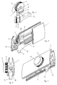
- Figur 1:
- Eine Ansicht der erfindungsgemäßen Feststellvorrichtung,
- Figur 2:
- einen Querschnitt durch die erfindungsgemäße Feststellvorrichtung,
- Figur 3:
- einen Teilschnitt durch die erfindungsgemäße Feststellvorrichtung und
- Figur 4:
- eine weitere Ansicht der erfindungsgemäßen Feststellvorrichtung.
- In den Figuren 1 bis 4 ist eine erfindungsgemäße Feststellvorrichtung gezeigt, die an einer vorzugsweise von Hand verfahrbaren Wand angeordnet ist. Die (nicht dargestellte) Wand geht in ihrem unteren Bereich in ein Profil 1 über, das im dargestellten Ausführungsbeispiel aus zwei Profilhalbschalen mit leicht gewölbt verlaufenden Außenseiten versehen ist (vgl. Figur 2).
- In dem Profil 1 ist eine kreisförmige Ausnehmung 2 vorgesehen, in welcher ein Drehknopf 3 gelagert ist. Die Ausnehmung 2 umschließt den Drehknopf 3 mit einem geringen Spiel, so dass das Eindringen von Schmutz oder Staub in den Spalt zwischen der Ausnehmung 2 und dem Drehknopf 3 weitestgehend verhindert werden kann. Der Drehknopf 3 ist auf seinem Außenumfang mit einer Rändelung 4 versehen, um eine sichere Betätigung des Drehknopfes 3 zu ermöglichen.
- Der Drehknopf 3 steht mit einem als Raststift ausgebildeten Feststellelement 5 in Wirkverbindung, so dass durch eine Betätigung des Drehknopfes 3 das Feststellelement 5 aus- bzw. eingefahren werden kann.
- Der Drehknopf 3 ist auf seiner Innenseite mit einem zentrischen Achsstummel 6 versehen, der eine drehbare Lagerung des Drehknopfes 3 in dem Profil 1 ermöglicht. Exzentrisch zu dem Achsstummel 6 ist in der Nähe des äußeren Randes des Drehknopfes 3 ein Exzenterstift 7 vorgesehen. Der Drehknopf 3 mit dem Achsstummel 6 und dem Exzenterstift 7 können als einstückiges Bauteil, zum Beispiel durch Spritzgießen, hergestellt sein.
- Der Exzenterstift 7 greift in eine Kulisse 8 ein, welche den Exzenterstift 7 in einem Langloch 9 aufnimmt. Die Kulisse 8 selbst ist mit dem Feststellelement 5, zum Beispiel über eine Schraubverbindung, verbunden.
- Das Feststellelement 5 ist in seiner Verschieberichtung in einem Träger 10 geführt, der verschieb- und festlegbar in einer in dem Profil 1 vorgesehenen Schiene 11 gehalten ist. In dem Profil 1 ist weiterhin eine als Viertelkreis ausgebildete Kreisbahn 12 vorgesehen, durch welche sich der Exzenterstift 7 hindurcherstreckt. Die Enden der Kreisbahn 12 dienen als Anschlag und begrenzen so die Drehbewegung des Drehknopfes 3 und damit den Verschiebeweg des Feststellelementes 5.
- Wenn der Drehknopf 3 gedreht wird, bewegt sich der Exzenterstift 7 in dem Langloch 9 der Kulisse 8 und bewegt dadurch das Feststellelement 5 nach unten bzw. nach oben - je nach Drehrichtung. Somit wird die Drehbewegung des Drehknopfes 3 in eine Längsbewegung des Feststellelementes 5 umgewandelt.
-
- 1
- Profil
- 2
- Ausnehmung
- 3
- Drehknopf
- 4
- Rändelung
- 5
- Feststellelement
- 6
- Achsstummel
- 7
- Exzenterstift
- 8
- Kulisse
- 9
- Langloch
- 10
- Träger
- 11
- Schiene
- 12
- Kreisbahn
Claims (9)
- Feststellvorrichtung für eine verfahrbare Wand, mit einem Feststellelement, das über ein von Hand betätigbares Stellglied in seine Wirkstellung bringbar ist, dadurch gekennzeichnet, dass das Stellglied als Drehknopf (3) ausgebildet ist, dessen Drehbewegung in eine Längsbewegung für das Feststellelement (5) umwandelbar ist.
- Feststellvorrichtung nach Anspruch 1, dadurch gekennzeichnet, dass der Drehknopf (3) in einer den Drehknopf (3) mit geringem Spiel umgebenden Ausnehmung (2) in der Wand angeordnet ist.
- Feststellvorrichtung nach einem der vorhergehenden Ansprüche, dadurch gekennzeichnet, dass der Drehknopf (3) auf seiner Umfangsfläche mit einer Rändelung (4) versehen ist.
- Feststellvorrichtung nach einem der vorhergehenden Ansprüche, dadurch gekennzeichnet, dass der Drehknopf (3) auf seiner zur Wand weisenden Seite mit einem Achsstummel (6) zu seiner drehbaren Lagerung und exzentrisch dazu mit einem Exzenterstift (7) versehen ist.
- Feststellvorrichtung nach einem der vorhergehenden Ansprüche, dadurch gekennzeichnet, dass der Exzenterstift (7) in eine Kulisse (8) eingreift, die mit dem Feststellelement (5) verbunden ist.
- Feststellvorrichtung nach einem der vorhergehenden Ansprüche, dadurch gekennzeichnet, dass der Exzenterstift (7) in einer in der Wand angeordneten Kreisbahn (12) geführt ist, deren Enden als Anschlag für die Drehbewegung des Drehknopfes (3) dienen.
- Feststellvorrichtung nach einem der vorhergehenden Ansprüche, dadurch gekennzeichnet, dass die Kreisbahn (12) als Viertelkreis ausgebildet ist.
- Feststellvorrichtung nach einem der vorhergehenden Ansprüche, dadurch gekennzeichnet, dass das Feststellelement (5) als Raststift ausgebildet ist.
- Feststellvorrichtung nach einem der vorhergehenden Ansprüche, dadurch gekennzeichnet, dass das Feststellelement (5) in einem Träger (10) in seiner Verschieberichtung geführt ist, der an einer in der Wand angeordneten Schiene (11) verschieb- und feststellbar gehalten ist.
Applications Claiming Priority (2)
| Application Number | Priority Date | Filing Date | Title |
|---|---|---|---|
| DE20306551U DE20306551U1 (de) | 2003-04-25 | 2003-04-25 | Feststellvorrichtung für eine verfahrbare Wand |
| PCT/EP2004/004322 WO2004097132A1 (de) | 2003-04-25 | 2004-04-23 | Festellvorrichtung für eine verfahrbare wand |
Publications (3)
| Publication Number | Publication Date |
|---|---|
| EP1620611A1 EP1620611A1 (de) | 2006-02-01 |
| EP1620611B1 true EP1620611B1 (de) | 2006-09-13 |
| EP1620611B2 EP1620611B2 (de) | 2010-10-20 |
Family
ID=27798497
Family Applications (1)
| Application Number | Title | Priority Date | Filing Date |
|---|---|---|---|
| EP20040729071 Expired - Lifetime EP1620611B2 (de) | 2003-04-25 | 2004-04-23 | Festellvorrichtung für eine verfahrbare wand |
Country Status (13)
| Country | Link |
|---|---|
| US (1) | US7357428B2 (de) |
| EP (1) | EP1620611B2 (de) |
| CN (1) | CN100402766C (de) |
| AT (1) | ATE339561T1 (de) |
| AU (1) | AU2004234510B2 (de) |
| BG (1) | BG65302B1 (de) |
| CA (1) | CA2494881A1 (de) |
| DE (2) | DE20306551U1 (de) |
| ES (1) | ES2273252T3 (de) |
| NO (1) | NO20045591L (de) |
| PT (1) | PT1620611E (de) |
| RU (1) | RU2344258C2 (de) |
| WO (1) | WO2004097132A1 (de) |
Cited By (1)
| Publication number | Priority date | Publication date | Assignee | Title |
|---|---|---|---|---|
| CN102640714A (zh) * | 2012-05-16 | 2012-08-22 | 蚌埠依爱电子科技有限责任公司 | 饲喂盘采食窗口的宽度调整结构 |
Families Citing this family (8)
| Publication number | Priority date | Publication date | Assignee | Title |
|---|---|---|---|---|
| DE102007032770A1 (de) * | 2007-07-13 | 2009-01-15 | Protektorwerk Florenz Maisch Gmbh & Co Kg | Profilelement |
| US8261500B2 (en) * | 2008-03-26 | 2012-09-11 | C.R. Laurence Company, Inc. | Wall panel system including a retractable floor anchor and method |
| DE202009009548U1 (de) * | 2009-07-10 | 2009-09-10 | Dorma Gmbh + Co. Kg | Deckenschienensystem zur Führung von Wandelementen |
| ITMI20120672A1 (it) * | 2012-04-23 | 2013-10-24 | Gewiss Spa | Dispositivo di chiusura |
| US10329759B2 (en) | 2012-09-17 | 2019-06-25 | Steelcase Inc. | Floor-to-ceiling partition wall assembly |
| CA2881683C (en) | 2012-09-17 | 2018-07-24 | Steelcase Inc. | Floor-to-ceiling partition wall assembly |
| USD987117S1 (en) | 2020-10-14 | 2023-05-23 | MillerKnoll, Inc. | Wall |
| US11814839B2 (en) | 2020-10-28 | 2023-11-14 | MillerKnoll, Inc. | Mobile wall including an alignment mechanism |
Family Cites Families (33)
| Publication number | Priority date | Publication date | Assignee | Title |
|---|---|---|---|---|
| US241998A (en) * | 1881-05-24 | haskell king | ||
| US1524005A (en) * | 1924-04-10 | 1925-01-20 | Wilson J G Corp | Locking means for doors |
| GB226264A (en) | 1924-06-05 | 1924-12-24 | David John Thomas | Window fastener |
| GB736439A (en) | 1953-02-23 | 1955-09-07 | Daniel Georg Martens | Safety spring lock |
| US2905495A (en) * | 1957-11-01 | 1959-09-22 | Robert M Adamson | Latch mechanisms |
| US2961263A (en) * | 1957-12-18 | 1960-11-22 | Amerock Corp | Sash lock for windows |
| US3201959A (en) * | 1962-09-04 | 1965-08-24 | Engineered Products Company | Safety lock |
| US3591218A (en) * | 1968-11-29 | 1971-07-06 | Cyril James Gowland | Security bolt |
| US3762750A (en) * | 1971-09-10 | 1973-10-02 | Keystone Consolidated Ind Inc | Dead bolt lock |
| GB2086978B (en) * | 1980-11-04 | 1984-10-10 | Safeways Wirral Locksmiths | Lock |
| DE3101725A1 (de) * | 1981-01-21 | 1982-08-05 | Aktiengesellschaft für Türautomation, 8600 Dübendorf | "schiebetueranlage" |
| US4555880A (en) * | 1982-03-15 | 1985-12-03 | Stow & Davis Furniture Company | Adjustable base for office landscaping system |
| FR2527284A1 (fr) * | 1982-05-19 | 1983-11-25 | Neiman Sa | Dispositif de solidarisation en rotation |
| FR2557623B1 (fr) * | 1983-12-28 | 1986-04-25 | Neiman Sa | Dispositif de commande debrayable d'un mecanisme de serrure a condamnation |
| AT381552B (de) * | 1985-01-02 | 1986-11-10 | Wimmer Hermann | Drehknopfanordnung an einem tuerblatt |
| US4691951A (en) * | 1985-10-19 | 1987-09-08 | Gerhard Fildan | Bolt assembly for a door set |
| US4688406A (en) * | 1986-04-01 | 1987-08-25 | Blumcraft Of Pittsburgh | Deadbolt lock mechanism |
| US4838058A (en) * | 1986-07-10 | 1989-06-13 | Matsumoto Metal Mfg. Co., Ltd. | Card lock |
| US4976122A (en) * | 1988-08-15 | 1990-12-11 | Pease Industries, Inc. | Deadbolt assembly having selectable backset |
| DE4133720C2 (de) * | 1991-10-11 | 1994-03-10 | Dorma Glas Gmbh | Feststell- und Verriegelungseinheit |
| IL110911A0 (en) | 1994-09-09 | 1994-11-28 | Mul T Lock Ltd | Locking device |
| US6607289B2 (en) * | 1995-10-04 | 2003-08-19 | Leon Lassovsky | Quick connect reflector holder |
| US6108989A (en) * | 1995-10-17 | 2000-08-29 | Dorma Gmbh & Co. Kg | Wall partition system and a device for securing a wall partition system |
| US6622534B1 (en) * | 1997-02-10 | 2003-09-23 | Lockmasters, Inc. | Dead bolt system having multiple security features |
| FI103357B (fi) * | 1997-06-11 | 1999-06-15 | Jukova Oy | Lukko, joka on vastakkaisilta puoliltaan avattavissa ja suljettavissa |
| DE19746208C2 (de) * | 1997-10-20 | 2000-04-06 | Dorma Gmbh & Co Kg | Laufschiene für ein Laufwerk für eine hängend gelagerte Trennwand |
| JP2000145245A (ja) * | 1998-11-04 | 2000-05-26 | Sumitomo Forestry Co Ltd | 引戸用施錠装置 |
| US6145356A (en) * | 1999-01-11 | 2000-11-14 | Thwing; Randy L. | Dual-function locks and sub-assemblies therefor |
| US6018915A (en) * | 1999-01-29 | 2000-02-01 | Pci Industries, Inc. | Sliding and locking wall panels |
| US6415565B1 (en) * | 2000-04-18 | 2002-07-09 | Vent-Alarm Corporation | Storm rail for sliding door |
| JP4195172B2 (ja) * | 2000-05-29 | 2008-12-10 | 美和ロック株式会社 | 引き違い戸の鎌錠装置 |
| ATE451521T1 (de) * | 2002-09-06 | 2009-12-15 | Hawa Ag | Vorrichtung zur verriegelung eines trennelements |
| US7201408B2 (en) * | 2005-02-28 | 2007-04-10 | Cennamo Jr Michael F | Slidable bolt assembly |
-
2003
- 2003-04-25 DE DE20306551U patent/DE20306551U1/de not_active Expired - Lifetime
-
2004
- 2004-04-23 CA CA 2494881 patent/CA2494881A1/en not_active Abandoned
- 2004-04-23 PT PT04729071T patent/PT1620611E/pt unknown
- 2004-04-23 EP EP20040729071 patent/EP1620611B2/de not_active Expired - Lifetime
- 2004-04-23 DE DE200450001494 patent/DE502004001494D1/de not_active Expired - Lifetime
- 2004-04-23 AT AT04729071T patent/ATE339561T1/de active
- 2004-04-23 ES ES04729071T patent/ES2273252T3/es not_active Expired - Lifetime
- 2004-04-23 US US10/518,976 patent/US7357428B2/en not_active Expired - Fee Related
- 2004-04-23 WO PCT/EP2004/004322 patent/WO2004097132A1/de not_active Ceased
- 2004-04-23 RU RU2004134574A patent/RU2344258C2/ru active
- 2004-04-23 AU AU2004234510A patent/AU2004234510B2/en not_active Ceased
- 2004-04-23 CN CNB2004800002035A patent/CN100402766C/zh not_active Expired - Fee Related
- 2004-10-04 BG BG108895A patent/BG65302B1/bg unknown
- 2004-12-22 NO NO20045591A patent/NO20045591L/no not_active Application Discontinuation
Cited By (2)
| Publication number | Priority date | Publication date | Assignee | Title |
|---|---|---|---|---|
| CN102640714A (zh) * | 2012-05-16 | 2012-08-22 | 蚌埠依爱电子科技有限责任公司 | 饲喂盘采食窗口的宽度调整结构 |
| CN102640714B (zh) * | 2012-05-16 | 2013-12-25 | 蚌埠依爱电子科技有限责任公司 | 饲喂盘采食窗口的宽度调整结构 |
Also Published As
| Publication number | Publication date |
|---|---|
| RU2344258C2 (ru) | 2009-01-20 |
| EP1620611B2 (de) | 2010-10-20 |
| CN100402766C (zh) | 2008-07-16 |
| WO2004097132A1 (de) | 2004-11-11 |
| BG108895A (en) | 2005-10-31 |
| ES2273252T3 (es) | 2007-05-01 |
| US20050252098A1 (en) | 2005-11-17 |
| NO20045591L (no) | 2005-01-12 |
| PT1620611E (pt) | 2007-01-31 |
| CN1697906A (zh) | 2005-11-16 |
| AU2004234510A1 (en) | 2004-11-11 |
| BG65302B1 (bg) | 2007-12-28 |
| CA2494881A1 (en) | 2004-11-11 |
| DE502004001494D1 (de) | 2006-10-26 |
| DE20306551U1 (de) | 2003-08-28 |
| AU2004234510B2 (en) | 2008-05-01 |
| US7357428B2 (en) | 2008-04-15 |
| EP1620611A1 (de) | 2006-02-01 |
| RU2004134574A (ru) | 2006-01-20 |
| ATE339561T1 (de) | 2006-10-15 |
Similar Documents
| Publication | Publication Date | Title |
|---|---|---|
| EP2851497B1 (de) | Justierbare Montagevorrichtung für ein Schiebeelement sowie Schiebevorrichtung | |
| DE69302213T2 (de) | Armlehne für Kraftfahrzeugsitze | |
| DE19646645C2 (de) | Behälter | |
| WO1998042938A1 (de) | Hebelverschluss | |
| DE2503272A1 (de) | Tuerschlossfalle | |
| EP0422678B1 (de) | Gepäckbox | |
| EP1620611B2 (de) | Festellvorrichtung für eine verfahrbare wand | |
| DE602004000781T2 (de) | Durch zweimaliges Drücken betätigte Schliessvorrichtung | |
| DE3645256C2 (de) | Fenster- und Türbeschlag | |
| WO2000060198A1 (de) | Verstellvorrichtung für ausstellfenster | |
| DE102008018738B4 (de) | Fahrzeugseitige Kupplungsbaugruppe einer Anhängerkupplung | |
| WO2004085782A1 (de) | Vorrichtung zum schliessen einer türe | |
| WO2009103405A1 (de) | Feststellvorrichtung für eine verfahrbare wand | |
| DE4013158C1 (en) | Roller blind covering car boot - incorporates swing arm passing through blind casing and pushbutton control | |
| DE10127425B4 (de) | Haltevorrichtung für bewegliche Verschlusselemente | |
| DE202007002416U1 (de) | Befestigungsschelle für Stabmattenzäune | |
| DE60003821T2 (de) | Motorischer Antrieb | |
| EP1780355A2 (de) | Betätigungsvorrichtung für die Haube eines Kraftfahrzeuges | |
| EP3670799A1 (de) | Verriegelungseinrichtung | |
| EP1662083B1 (de) | Tür- oder Fensterfeststellvorrichtung | |
| DE10293962B4 (de) | Türriegel | |
| DE3839911C2 (de) | Elektrischer Schalter | |
| DE202007017951U1 (de) | Gehäuse mit einer darin angeordneten Baugruppe | |
| WO1991017333A1 (de) | Mit schlosseinrichtung versehener versenkbarer schwenkhebelverschluss | |
| DE29510071U1 (de) | Radiusbetätiger für Sicherheitsschalter |
Legal Events
| Date | Code | Title | Description |
|---|---|---|---|
| PUAI | Public reference made under article 153(3) epc to a published international application that has entered the european phase |
Free format text: ORIGINAL CODE: 0009012 |
|
| 17P | Request for examination filed |
Effective date: 20051125 |
|
| AK | Designated contracting states |
Kind code of ref document: A1 Designated state(s): AT BE BG CH CY CZ DE DK EE ES FI FR GB GR HU IE IT LI LU MC NL PL PT RO SE SI SK TR |
|
| GRAP | Despatch of communication of intention to grant a patent |
Free format text: ORIGINAL CODE: EPIDOSNIGR1 |
|
| DAX | Request for extension of the european patent (deleted) | ||
| GRAS | Grant fee paid |
Free format text: ORIGINAL CODE: EPIDOSNIGR3 |
|
| GRAA | (expected) grant |
Free format text: ORIGINAL CODE: 0009210 |
|
| AK | Designated contracting states |
Kind code of ref document: B1 Designated state(s): AT BE BG CH CY CZ DE DK EE ES FI FR GB GR HU IE IT LI LU MC NL PL PT RO SE SI SK TR |
|
| PG25 | Lapsed in a contracting state [announced via postgrant information from national office to epo] |
Ref country code: IT Free format text: LAPSE BECAUSE OF FAILURE TO SUBMIT A TRANSLATION OF THE DESCRIPTION OR TO PAY THE FEE WITHIN THE PRESCRIBED TIME-LIMIT;WARNING: LAPSES OF ITALIAN PATENTS WITH EFFECTIVE DATE BEFORE 2007 MAY HAVE OCCURRED AT ANY TIME BEFORE 2007. THE CORRECT EFFECTIVE DATE MAY BE DIFFERENT FROM THE ONE RECORDED. Effective date: 20060913 Ref country code: SI Free format text: LAPSE BECAUSE OF FAILURE TO SUBMIT A TRANSLATION OF THE DESCRIPTION OR TO PAY THE FEE WITHIN THE PRESCRIBED TIME-LIMIT Effective date: 20060913 Ref country code: SK Free format text: LAPSE BECAUSE OF FAILURE TO SUBMIT A TRANSLATION OF THE DESCRIPTION OR TO PAY THE FEE WITHIN THE PRESCRIBED TIME-LIMIT Effective date: 20060913 Ref country code: PL Free format text: LAPSE BECAUSE OF FAILURE TO SUBMIT A TRANSLATION OF THE DESCRIPTION OR TO PAY THE FEE WITHIN THE PRESCRIBED TIME-LIMIT Effective date: 20060913 Ref country code: RO Free format text: LAPSE BECAUSE OF FAILURE TO SUBMIT A TRANSLATION OF THE DESCRIPTION OR TO PAY THE FEE WITHIN THE PRESCRIBED TIME-LIMIT Effective date: 20060913 Ref country code: IE Free format text: LAPSE BECAUSE OF FAILURE TO SUBMIT A TRANSLATION OF THE DESCRIPTION OR TO PAY THE FEE WITHIN THE PRESCRIBED TIME-LIMIT Effective date: 20060913 Ref country code: CZ Free format text: LAPSE BECAUSE OF FAILURE TO SUBMIT A TRANSLATION OF THE DESCRIPTION OR TO PAY THE FEE WITHIN THE PRESCRIBED TIME-LIMIT Effective date: 20060913 |
|
| REG | Reference to a national code |
Ref country code: GB Ref legal event code: FG4D Free format text: NOT ENGLISH |
|
| REG | Reference to a national code |
Ref country code: CH Ref legal event code: EP |
|
| REG | Reference to a national code |
Ref country code: IE Ref legal event code: FG4D Free format text: LANGUAGE OF EP DOCUMENT: GERMAN |
|
| REF | Corresponds to: |
Ref document number: 502004001494 Country of ref document: DE Date of ref document: 20061026 Kind code of ref document: P |
|
| PG25 | Lapsed in a contracting state [announced via postgrant information from national office to epo] |
Ref country code: DK Free format text: LAPSE BECAUSE OF FAILURE TO SUBMIT A TRANSLATION OF THE DESCRIPTION OR TO PAY THE FEE WITHIN THE PRESCRIBED TIME-LIMIT Effective date: 20061213 Ref country code: BG Free format text: LAPSE BECAUSE OF FAILURE TO SUBMIT A TRANSLATION OF THE DESCRIPTION OR TO PAY THE FEE WITHIN THE PRESCRIBED TIME-LIMIT Effective date: 20061213 |
|
| REG | Reference to a national code |
Ref country code: SE Ref legal event code: TRGR |
|
| GBT | Gb: translation of ep patent filed (gb section 77(6)(a)/1977) |
Effective date: 20061207 |
|
| REG | Reference to a national code |
Ref country code: PT Ref legal event code: SC4A Free format text: AVAILABILITY OF NATIONAL TRANSLATION Effective date: 20061212 |
|
| ET | Fr: translation filed | ||
| REG | Reference to a national code |
Ref country code: IE Ref legal event code: FD4D |
|
| REG | Reference to a national code |
Ref country code: ES Ref legal event code: FG2A Ref document number: 2273252 Country of ref document: ES Kind code of ref document: T3 |
|
| PLBI | Opposition filed |
Free format text: ORIGINAL CODE: 0009260 |
|
| PLAX | Notice of opposition and request to file observation + time limit sent |
Free format text: ORIGINAL CODE: EPIDOSNOBS2 |
|
| 26 | Opposition filed |
Opponent name: GEZE GMBH Effective date: 20070612 |
|
| NLR1 | Nl: opposition has been filed with the epo |
Opponent name: GEZE GMBH |
|
| PLBB | Reply of patent proprietor to notice(s) of opposition received |
Free format text: ORIGINAL CODE: EPIDOSNOBS3 |
|
| PG25 | Lapsed in a contracting state [announced via postgrant information from national office to epo] |
Ref country code: GR Free format text: LAPSE BECAUSE OF FAILURE TO SUBMIT A TRANSLATION OF THE DESCRIPTION OR TO PAY THE FEE WITHIN THE PRESCRIBED TIME-LIMIT Effective date: 20061214 |
|
| PG25 | Lapsed in a contracting state [announced via postgrant information from national office to epo] |
Ref country code: EE Free format text: LAPSE BECAUSE OF FAILURE TO SUBMIT A TRANSLATION OF THE DESCRIPTION OR TO PAY THE FEE WITHIN THE PRESCRIBED TIME-LIMIT Effective date: 20060913 |
|
| PGRI | Patent reinstated in contracting state [announced from national office to epo] |
Ref country code: IT Effective date: 20080601 |
|
| REG | Reference to a national code |
Ref country code: CH Ref legal event code: PL |
|
| PG25 | Lapsed in a contracting state [announced via postgrant information from national office to epo] |
Ref country code: CH Free format text: LAPSE BECAUSE OF NON-PAYMENT OF DUE FEES Effective date: 20080430 Ref country code: LI Free format text: LAPSE BECAUSE OF NON-PAYMENT OF DUE FEES Effective date: 20080430 |
|
| PG25 | Lapsed in a contracting state [announced via postgrant information from national office to epo] |
Ref country code: MC Free format text: LAPSE BECAUSE OF NON-PAYMENT OF DUE FEES Effective date: 20070430 |
|
| PGFP | Annual fee paid to national office [announced via postgrant information from national office to epo] |
Ref country code: ES Payment date: 20090422 Year of fee payment: 6 |
|
| PG25 | Lapsed in a contracting state [announced via postgrant information from national office to epo] |
Ref country code: CY Free format text: LAPSE BECAUSE OF FAILURE TO SUBMIT A TRANSLATION OF THE DESCRIPTION OR TO PAY THE FEE WITHIN THE PRESCRIBED TIME-LIMIT Effective date: 20060913 |
|
| PGFP | Annual fee paid to national office [announced via postgrant information from national office to epo] |
Ref country code: FI Payment date: 20090417 Year of fee payment: 6 Ref country code: FR Payment date: 20090414 Year of fee payment: 6 Ref country code: IT Payment date: 20090422 Year of fee payment: 6 Ref country code: LU Payment date: 20090414 Year of fee payment: 6 Ref country code: NL Payment date: 20090415 Year of fee payment: 6 Ref country code: PT Payment date: 20090401 Year of fee payment: 6 Ref country code: SE Payment date: 20090416 Year of fee payment: 6 Ref country code: TR Payment date: 20090403 Year of fee payment: 6 |
|
| PG25 | Lapsed in a contracting state [announced via postgrant information from national office to epo] |
Ref country code: HU Free format text: LAPSE BECAUSE OF FAILURE TO SUBMIT A TRANSLATION OF THE DESCRIPTION OR TO PAY THE FEE WITHIN THE PRESCRIBED TIME-LIMIT Effective date: 20070314 |
|
| PGFP | Annual fee paid to national office [announced via postgrant information from national office to epo] |
Ref country code: BE Payment date: 20090528 Year of fee payment: 6 |
|
| PLAB | Opposition data, opponent's data or that of the opponent's representative modified |
Free format text: ORIGINAL CODE: 0009299OPPO |
|
| PGFP | Annual fee paid to national office [announced via postgrant information from national office to epo] |
Ref country code: GB Payment date: 20090421 Year of fee payment: 6 |
|
| R26 | Opposition filed (corrected) |
Opponent name: GEZE GMBH Effective date: 20070612 |
|
| NLR1 | Nl: opposition has been filed with the epo |
Opponent name: GEZE GMBH |
|
| PUAH | Patent maintained in amended form |
Free format text: ORIGINAL CODE: 0009272 |
|
| STAA | Information on the status of an ep patent application or granted ep patent |
Free format text: STATUS: PATENT MAINTAINED AS AMENDED |
|
| 27A | Patent maintained in amended form |
Effective date: 20101020 |
|
| AK | Designated contracting states |
Kind code of ref document: B2 Designated state(s): AT BE BG CH CY CZ DE DK EE ES FI FR GB GR HU IE IT LI LU MC NL PL PT RO SE SI SK TR |
|
| BERE | Be: lapsed |
Owner name: DORMA G.M.B.H. + CO. KG Effective date: 20100430 |
|
| REG | Reference to a national code |
Ref country code: PT Ref legal event code: MM4A Free format text: LAPSE DUE TO NON-PAYMENT OF FEES Effective date: 20101025 |
|
| REG | Reference to a national code |
Ref country code: NL Ref legal event code: V1 Effective date: 20101101 |
|
| EUG | Se: european patent has lapsed | ||
| GBPC | Gb: european patent ceased through non-payment of renewal fee |
Effective date: 20100423 |
|
| REG | Reference to a national code |
Ref country code: FR Ref legal event code: ST Effective date: 20101230 |
|
| REG | Reference to a national code |
Ref country code: PT Ref legal event code: MP4A Effective date: 20110120 |
|
| PG25 | Lapsed in a contracting state [announced via postgrant information from national office to epo] |
Ref country code: NL Free format text: LAPSE BECAUSE OF NON-PAYMENT OF DUE FEES Effective date: 20101101 Ref country code: FI Free format text: LAPSE BECAUSE OF NON-PAYMENT OF DUE FEES Effective date: 20100423 |
|
| PG25 | Lapsed in a contracting state [announced via postgrant information from national office to epo] |
Ref country code: PT Free format text: LAPSE BECAUSE OF NON-PAYMENT OF DUE FEES Effective date: 20101025 |
|
| PG25 | Lapsed in a contracting state [announced via postgrant information from national office to epo] |
Ref country code: IT Free format text: LAPSE BECAUSE OF NON-PAYMENT OF DUE FEES Effective date: 20100423 Ref country code: BE Free format text: LAPSE BECAUSE OF NON-PAYMENT OF DUE FEES Effective date: 20100430 Ref country code: GB Free format text: LAPSE BECAUSE OF NON-PAYMENT OF DUE FEES Effective date: 20100423 |
|
| REG | Reference to a national code |
Ref country code: ES Ref legal event code: FD2A Effective date: 20110711 |
|
| PG25 | Lapsed in a contracting state [announced via postgrant information from national office to epo] |
Ref country code: ES Free format text: LAPSE BECAUSE OF NON-PAYMENT OF DUE FEES Effective date: 20110629 |
|
| PG25 | Lapsed in a contracting state [announced via postgrant information from national office to epo] |
Ref country code: ES Free format text: LAPSE BECAUSE OF NON-PAYMENT OF DUE FEES Effective date: 20100424 |
|
| PG25 | Lapsed in a contracting state [announced via postgrant information from national office to epo] |
Ref country code: FR Free format text: LAPSE BECAUSE OF NON-PAYMENT OF DUE FEES Effective date: 20100430 |
|
| PG25 | Lapsed in a contracting state [announced via postgrant information from national office to epo] |
Ref country code: LU Free format text: LAPSE BECAUSE OF NON-PAYMENT OF DUE FEES Effective date: 20100423 Ref country code: SE Free format text: LAPSE BECAUSE OF NON-PAYMENT OF DUE FEES Effective date: 20100424 |
|
| PG25 | Lapsed in a contracting state [announced via postgrant information from national office to epo] |
Ref country code: TR Free format text: LAPSE BECAUSE OF NON-PAYMENT OF DUE FEES Effective date: 20100423 |
|
| PGFP | Annual fee paid to national office [announced via postgrant information from national office to epo] |
Ref country code: AT Payment date: 20140411 Year of fee payment: 11 |
|
| REG | Reference to a national code |
Ref country code: DE Ref legal event code: R081 Ref document number: 502004001494 Country of ref document: DE Owner name: DORMAKABA DEUTSCHLAND GMBH, DE Free format text: FORMER OWNER: DORMA GMBH + CO. KG, 58256 ENNEPETAL, DE Effective date: 20141210 Ref country code: DE Ref legal event code: R081 Ref document number: 502004001494 Country of ref document: DE Owner name: DORMA DEUTSCHLAND GMBH, DE Free format text: FORMER OWNER: DORMA GMBH + CO. KG, 58256 ENNEPETAL, DE Effective date: 20141210 |
|
| REG | Reference to a national code |
Ref country code: DE Ref legal event code: R082 Ref document number: 502004001494 Country of ref document: DE Representative=s name: BALDER IP LAW, S.L., ES |
|
| REG | Reference to a national code |
Ref country code: AT Ref legal event code: MM01 Ref document number: 339561 Country of ref document: AT Kind code of ref document: T Effective date: 20150423 |
|
| PG25 | Lapsed in a contracting state [announced via postgrant information from national office to epo] |
Ref country code: AT Free format text: LAPSE BECAUSE OF NON-PAYMENT OF DUE FEES Effective date: 20150423 |
|
| REG | Reference to a national code |
Ref country code: DE Ref legal event code: R081 Ref document number: 502004001494 Country of ref document: DE Owner name: DORMA-GLAS GMBH, DE Free format text: FORMER OWNER: DORMA DEUTSCHLAND GMBH, 58256 ENNEPETAL, DE Ref country code: DE Ref legal event code: R082 Ref document number: 502004001494 Country of ref document: DE Representative=s name: BALDER IP LAW, S.L., ES Ref country code: DE Ref legal event code: R081 Ref document number: 502004001494 Country of ref document: DE Owner name: DORMAKABA DEUTSCHLAND GMBH, DE Free format text: FORMER OWNER: DORMA DEUTSCHLAND GMBH, 58256 ENNEPETAL, DE |
|
| PGFP | Annual fee paid to national office [announced via postgrant information from national office to epo] |
Ref country code: DE Payment date: 20210420 Year of fee payment: 18 |
|
| REG | Reference to a national code |
Ref country code: DE Ref legal event code: R081 Ref document number: 502004001494 Country of ref document: DE Owner name: DORMA-GLAS GMBH, DE Free format text: FORMER OWNER: DORMAKABA DEUTSCHLAND GMBH, 58256 ENNEPETAL, DE |
|
| REG | Reference to a national code |
Ref country code: DE Ref legal event code: R119 Ref document number: 502004001494 Country of ref document: DE |
|
| PG25 | Lapsed in a contracting state [announced via postgrant information from national office to epo] |
Ref country code: DE Free format text: LAPSE BECAUSE OF NON-PAYMENT OF DUE FEES Effective date: 20221103 |