EP1621066A2 - Dispositif de protection pour machines agricoles - Google Patents
Dispositif de protection pour machines agricoles Download PDFInfo
- Publication number
- EP1621066A2 EP1621066A2 EP05014714A EP05014714A EP1621066A2 EP 1621066 A2 EP1621066 A2 EP 1621066A2 EP 05014714 A EP05014714 A EP 05014714A EP 05014714 A EP05014714 A EP 05014714A EP 1621066 A2 EP1621066 A2 EP 1621066A2
- Authority
- EP
- European Patent Office
- Prior art keywords
- protective device
- work machine
- foreign body
- agricultural work
- crop
- Prior art date
- Legal status (The legal status is an assumption and is not a legal conclusion. Google has not performed a legal analysis and makes no representation as to the accuracy of the status listed.)
- Granted
Links
- 230000001681 protective effect Effects 0.000 claims description 41
- 230000001133 acceleration Effects 0.000 claims description 15
- 238000001514 detection method Methods 0.000 claims description 15
- 210000000056 organ Anatomy 0.000 claims description 2
- 239000004575 stone Substances 0.000 abstract description 7
- 206010070245 Foreign body Diseases 0.000 description 15
- 230000008901 benefit Effects 0.000 description 6
- 230000001419 dependent effect Effects 0.000 description 4
- 239000000463 material Substances 0.000 description 3
- 230000004044 response Effects 0.000 description 3
- 230000008021 deposition Effects 0.000 description 2
- 230000000694 effects Effects 0.000 description 2
- 238000005204 segregation Methods 0.000 description 2
- 241000251169 Alopias vulpinus Species 0.000 description 1
- XEEYBQQBJWHFJM-UHFFFAOYSA-N Iron Chemical group [Fe] XEEYBQQBJWHFJM-UHFFFAOYSA-N 0.000 description 1
- 230000004913 activation Effects 0.000 description 1
- 238000010276 construction Methods 0.000 description 1
- 238000013016 damping Methods 0.000 description 1
- 238000011156 evaluation Methods 0.000 description 1
- 230000005294 ferromagnetic effect Effects 0.000 description 1
- 238000003306 harvesting Methods 0.000 description 1
- 230000001105 regulatory effect Effects 0.000 description 1
- 230000035945 sensitivity Effects 0.000 description 1
- 238000000926 separation method Methods 0.000 description 1
- 230000001960 triggered effect Effects 0.000 description 1
Images
Classifications
-
- A—HUMAN NECESSITIES
- A01—AGRICULTURE; FORESTRY; ANIMAL HUSBANDRY; HUNTING; TRAPPING; FISHING
- A01D—HARVESTING; MOWING
- A01D75/00—Accessories for harvesters or mowers
- A01D75/18—Safety devices for parts of the machines
- A01D75/187—Removing foreign objects
Definitions
- the invention relates to a protective device for agricultural machines according to the preamble of claims 1 and 15.
- the acoustic sensor assembly consists of a sensor bar, which is arranged across the width of the bottom of the feederhouse and an acoustic transducer, which is attached to the sensor bar.
- the feeder takes in its interior a guided by pulleys designed as a chain conveyor pulling means.
- the deflecting roller arranged in the transfer area between the grain cutting unit and the inclined conveyor is assigned to the lower side of the bottom of the inclined conveyor the sensor arrangement of the protective device.
- the foreign body signals generated by the protective device lead to the activation of a downstream ejection device in the flow direction of the measuring sensor arrangement.
- the ejection device releases an outlet opening extending over the entire cross section of the inclined conveyor in the bottom of the inclined conveyor so that the crop stream containing the foreign object (s) detected is conveyed out of the inclined conveyor through this outlet opening.
- a disadvantage of this known protective device is that the protective device detects the stones with only one sensor and a more accurate position of the foreign body is not determined.
- To remove a stone from the crop is the as Fall door trained ejection opening operated, which extends over the entire width of the feederhouse, so that in addition to the determined stone a considerable amount of crop exits the feederhouse.
- the trap door is also relatively heavy due to their size, so that high opening forces are required for opening and closing.
- the sensor bar can recognize stones several times because they are not removed immediately after the first detection, which ultimately leads to the drop door of the feeder conveyor being left open for a longer period of time.
- the separation of functions between the location of the foreign matter sensing and the foreign body ejection results in a relatively bulky construction and also has the disadvantage that segregation may have taken place up to the location of the foreign body ejection, so that the foreign body does not reach the ejection flap during its opening phase and thus not is deposited.
- the invention is therefore based on the object to provide a protective device which avoids the disadvantages of the prior art and in particular ensures a spatially resolved, high-precision foreign body detection and at the same time the loss of crop at the moment of foreign body deposition is reduced.
- the Sensieretti detect the foreign body independently of each other spatially resolved, the position of the foreign body can be located more accurately. This has the particular advantage that the foreign body can be deposited locally more precisely, so that the loss of crop during the FremdMechabscheidevorganges reduced.
- each sensing element is in operative connection with at least one pressure sensor or at least one vibration sensor, the force acting on each sensing element dependent on the foreign body can be determined separately.
- the pressure sensor is designed as a load cell with which the force exerted by the crop and / or the foreign body on the sensing element force can be determined directly.
- a particularly cost-effective design of the protective device results when the vibration sensor is designed as a conventional knock sensor.
- the sensing element is mounted on at least one elastic spring-damper element, the sensing element relative to the housing of the feederhouse and the adjacent sensing elements can be decoupled, so that the influence of interference signals is reduced.
- the sensor generates a pressure and / or acceleration signal in response to a force exerted on the sensing element pressure and / or in response to an acceleration of the Sensierettis which is proportional to the pressure and / or acceleration, which of the crop and / or force exerted by the foreign bodies on the sensing elements can be determined in a structurally simple manner.
- This also has the advantage that foreign bodies embedded in the material layer can be detected very precisely by pressure sensors by compressing the material mat while foreign bodies transported with little or no crop throughput can be detected very well by acceleration sensors, since the damping properties of the crop layer are then eliminated.
- the control unit By comparing the foreign-body-dependent signals generated by the sensors in a control unit with a threshold value, and the control unit generates ejection command signals associated with the respective sensing elements, if that Signal exceeds the threshold, it can be determined whether the signals are triggered by foreign bodies or the crop and foreign bodies can be automatically discharged, depending on the result of the comparison.
- the threshold is modifiable, it can be adjusted to machine and crop specific parameters such as vehicle speed, crop characteristics, and regionally different foreign body structures.
- This has the particular advantage that the detection sensitivity can be adjusted to the crop speed and the moisture-dependent crop density, since in particular these two crop parameters significantly influence the detection accuracy.
- the foreign body detector is arranged at an inlet end of an inclined conveyor on the agricultural machine.
- This arrangement of the protective device has the advantage that it remains when changing the cutting unit on the agricultural machine, so that not every cutting unit must be equipped with a separate protection device.
- the foreign body detector is arranged in a catchment area downstream of a cutter bar of a cutting unit, so that the foreign bodies are detected early.
- this protective device makes it possible to determine more precisely at which point of the field the foreign body was picked up by the cutting unit.
- the inclined conveyor advantageously has a deflection drum and a bottom and the sensing elements of the foreign body detector are at least partially disposed below the deflection drum in the region of the bottom, so that the crop and the foreign body from the deflection drum against the sensing units be pressed. This improves in particular the detection accuracy of embedded in the Erntegutmatte smaller foreign bodies.
- the cutting unit of the agricultural machine has a feed auger and a cutting trough and the sensing elements of the foreign body detector are at least partially disposed below the auger in the field of cutting trough on the cutting, so that the crop is pressed by the feed roller against the sensing units ,
- this also has the advantage that foreign bodies can be detected early and removed from the agricultural harvesting machine.
- an adjustable feed gap is present between tail pulley and / or auger and the sensing elements of the foreign body detector, can also be preset by mechanical means from which size the foreign body to be detected by the protection device. Due to the fact that the crop passing through the intake nip is constricted to the cross-section of the intake nip and thereby compressed, an undeformable foreign body surrounded by the crop can also be detected by the protective device.
- a particularly advantageous embodiment of the protective device results when the foreign body detector is a foreign body-recognizing as well as FremdMechausdorfdes organ, so that the foreign body is discharged at the moment in which it is detected.
- this has the particular advantage that segregation processes within the material layer have essentially no influence on the deposition accuracy of the foreign body detector.
- each sensing element of the foreign body detector can be pivoted automatically via an actuator designed as a piston-cylinder unit individually, wherein the actuator is connected to the control unit, the proportion of Missionschleusenden crop transverse to the direction of travel can be limited to the area in which detects the foreign body have been.
- the sensing elements can be pivoted so that they are arranged in all positions outside the cross section of the inclined conveyor, so that the movement of the Erntegutstrom is not hindered by the foreign body detector.
- the piston of the piston-cylinder unit arrives as soon as the control unit transmits an ejection command signal to the associated actuator, whereby the sensing element pivots from a detection position to an ejection position and releases an ejection opening
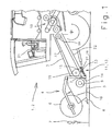
- FIG. 1 an executed as a self-propelled combine harvester 1 agricultural machine 2 is shown in the side view, at the feederhouse 3, a cutting unit 4 is arranged.
- the cutting unit 4 consists of a cutting table 5 and an attached, rotating reel 6.
- the reel 6 ensures a continuous acceptance of the crop 7 and for a uniform promotion of the crop 7 through the cutting unit 4 therethrough.
- the crop 7 is cut off by a mounted in the front region of the cutting unit 4 cutter bar 8 and then promoted by means of the reel 6 to a arranged in the cutting table 5 feed screw 9.
- the intake screw 9 leads the crop to the feederhouse 3, which forwards the crop 7 to a threshing device 10.
- the combine harvester 1 has a protective device 11, which consists essentially of the foreign body detector 13 according to the invention and to be described in more detail below.
- the foreign body detector 13 With the foreign body detector 13, foreign objects such as stones or metallic objects are detected in the crop 7.
- the foreign body detector 13 is arranged in the catchment area 15 of the inclined conveyor 3 on the combine harvester 1.
- the inclined conveyor 3 is formed by a housing 18 which receives in its interior a circulating drums 19 circulating chain conveyor 17.
- the sensing elements 23 of the foreign body detector 13 according to the invention are located underneath the front-side deflection drum 19 in the region of the base 22 of the inclined conveyor 3 which forms the bottom-side closure of the housing 18 and sense the crop 7 which has been underpinned.
- the sensing elements 23 of the foreign body detector 13 can be mounted in a mowing bar 8 downstream catchment area 16 of the cutting unit 4 on the cutting unit 4.
- the sensing elements 23 of the Foreign body detector 13 may be mounted below the auger 9 in a region of a cutting trough 14 on the cutting unit 4.
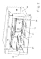
- the feederhouse 3 is shown in perspective disassembled cutting unit 4 in the first embodiment of the protective device 11.
- the inclined conveyor 3 consists of a chain conveyor 17 which is installed in a housing 18.
- To the chain conveyor 17 includes a rotating counterclockwise tail pulley 19 which is mounted at the front end of the housing 18 and further includes a number of conveyor chains 20, which wrap around the tail pulley 19 from each other.
- the conveyor chains 20 are connected to each other via conveyor bars 21 which convey the crop 7 (not shown) from the cutting unit via the bottom 22 of the housing 18.
- Below the deflection drum 19 is located in the region of the bottom 22 of the housing 18 of the foreign body detector 13, wherein the foreign body detector 13 extends across the width of the bottom 22.
- the foreign body detector 13 consists of several transverse to the direction of the agricultural machine 2 juxtaposed sensing elements 23, which detect the foreign body in the crop stream 7 independently of each other spatially resolved.
- the crop 7 is pressed against the sensing elements 23 when entering the inclined conveyor 3 with the deflection drum 19 and the conveyor belts 21.
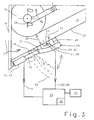
- FIG. 3 shows an enlarged section of the intake region 15 of the inclined conveyor 3.
- the transversely to the crop flow direction adjacent sensing elements 23 are mounted on elastic spring-damper elements 24, which in turn are pivotally mounted on the housing 18 of the inclined conveyor 3 about a rotation axis 34.
- the position of the deflection drum 19 with respect to the housing 18 of the inclined conveyor 3 is changeable transversely to the direction of movement of the crop 7 via an adjusting and fastening device 38, so that a pull-in gap 39 between the deflection drum 19 and the sensing elements 23 of the foreign body detector 13 is adjustable.
- the crop 7 passing through the intake nip 39 is constricted by the intake nip 39 and thereby compressed, whereby the foreign body enveloped by the crop 7 can be detected.
- Each sensing element 23 is in operative connection with a respective vibration sensor 26 designed as a knock sensor 25, which generates an acceleration signal SB as a function of an acceleration of the sensing element 23.
- the acceleration of the Sensierettis 23 is proportional to a, for example, by the crop 7 and / or the foreign body acting on the sensing element 23 force. It is possible that each sensing element 23 is in operative connection with a pressure sensor 28 designed as a load cell 27, which generates a pressure signal SD in response to a force acting on the sensing element 23.
- the respective sensors 25-28 are connected to a control unit 29, to which the respective pressure or acceleration signals SD, SB are transmitted.
- the control unit 29 compares the pressure or acceleration signals SD, SB with a threshold value 30 stored in the control unit 29, wherein the threshold value 30 in each case forms a measure for the foreign body (s) to be detected.
- the control unit 29 is also connected to a control panel 31, via which an operator can preselect the threshold value 30 and store it in the control unit 29.
- the threshold value 30 may also be predetermined by the manufacturer in the form of characteristic curves which are stored in the control unit 29. For example, the characteristic curves could determine the threshold value 30 as a function of the size of the intake nip 39, the moisture content of the crop, the crop throughput or the throughput speed.
- the control unit 29 For those pressure or acceleration signals SD, SB which exceed the threshold value 30, the control unit 29 generates ejection commands A associated with the respective sensing elements 23.
- the foreign body detector 13 is designed so that it can both recognize foreign bodies as well as eject them from the inclined conveyor 3 according to FIG.
- the actuator 33 is connected to the control unit 29.
- the piston rod 40 of the piston-cylinder unit 32 moves in and the associated sensing element 23 pivots clockwise into the ejection position 36.
- the piston moves Cylinder unit 32 again and the sensing element 23 is pivoted back counterclockwise in the detection position 35. So that the foreign body is reliably discharged from the crop 7, the sensing element 23, which has detected the foreign body, could always be pivoted together with the sensing elements 23 adjacent to it. How far the sensing element 23 is pivoted, for example, could be regulated by the fact that the travel of the piston rod 40 of the actuator 33 is set in dependence on the intake nip 39.
- the sensing elements 23 of the foreign body detector 13 may also be non-contact sensing elements 23 whose sensors, for example, sense ferromagnetic or metallic foreign bodies such as iron parts or whose sensors illuminate the crop.
- control device 29 could be connected to a display unit, on which is displayed, which sensor 25, 26, 27, 28 detects a foreign body, or whether the sensing element 23 is in a detection position 35 or in the ejection position 36.
- the control unit 29 may also be connected to a quick stop device which shuts off the cutter 4 and / or the feeder 3 and / or the thresher 10 as soon as the guard 11 detects a foreign object to protect the machine parts from damage and to remove the debris can. It is within the skill of one skilled in the art to modify the described embodiments in a manner not shown or to use in other machine systems to achieve the effects described, without departing from the scope of the invention.
Landscapes
- Life Sciences & Earth Sciences (AREA)
- Environmental Sciences (AREA)
- Harvester Elements (AREA)
- Catching Or Destruction (AREA)
- Threshing Machine Elements (AREA)
- Agricultural Machines (AREA)
- Soil Working Implements (AREA)
Applications Claiming Priority (1)
| Application Number | Priority Date | Filing Date | Title |
|---|---|---|---|
| DE102004035928A DE102004035928A1 (de) | 2004-07-23 | 2004-07-23 | Schutzvorrichtung für landwirtschaftliche Arbeitsmaschinen |
Publications (4)
| Publication Number | Publication Date |
|---|---|
| EP1621066A2 true EP1621066A2 (fr) | 2006-02-01 |
| EP1621066A3 EP1621066A3 (fr) | 2006-06-21 |
| EP1621066B1 EP1621066B1 (fr) | 2008-02-20 |
| EP1621066B2 EP1621066B2 (fr) | 2013-08-07 |
Family
ID=35395700
Family Applications (1)
| Application Number | Title | Priority Date | Filing Date |
|---|---|---|---|
| EP05014714.9A Expired - Lifetime EP1621066B2 (fr) | 2004-07-23 | 2005-07-07 | Dispositif de protection pour machines agricoles |
Country Status (3)
| Country | Link |
|---|---|
| EP (1) | EP1621066B2 (fr) |
| AT (1) | ATE386428T1 (fr) |
| DE (2) | DE102004035928A1 (fr) |
Cited By (4)
| Publication number | Priority date | Publication date | Assignee | Title |
|---|---|---|---|---|
| CN109287254A (zh) * | 2018-11-15 | 2019-02-01 | 雷沃重工股份有限公司 | 排石装置及收获机 |
| BE1025479B1 (de) * | 2017-03-17 | 2019-03-18 | Deere & Company | Landwirtschaftliche Erntemaschine zur Bearbeitung und Förderung von Erntegut mit einer Sensoranordnung zur Erkennung von unerwünschten Gefahr- und Inhaltsstoffen im Erntegut |
| CN118489400A (zh) * | 2024-04-30 | 2024-08-16 | 中联农业机械股份有限公司 | 用于青贮机的控制方法、装置、青贮机及存储介质 |
| EP4623667A1 (fr) * | 2024-03-27 | 2025-10-01 | CLAAS Selbstfahrende Erntemaschinen GmbH | Moissonneuse agricole |
Families Citing this family (2)
| Publication number | Priority date | Publication date | Assignee | Title |
|---|---|---|---|---|
| BE1021124B1 (nl) | 2013-01-18 | 2016-01-11 | Cnh Industrial Belgium Nv | Detectietoestel voor het detecteren van een vreemd voorwerp voor een oogstmachine. |
| DE102020127544B4 (de) | 2020-10-20 | 2022-05-19 | Bernd Knospe | Landwirtschaftliche Maschine mit einer Fördervorrichtung |
Citations (1)
| Publication number | Priority date | Publication date | Assignee | Title |
|---|---|---|---|---|
| DE3100045A1 (de) | 1980-01-04 | 1982-01-21 | Sperry Corp., 10104 New York, N.Y. | Schutzvorrichtung fuer erntemaschinen |
Family Cites Families (14)
| Publication number | Priority date | Publication date | Assignee | Title |
|---|---|---|---|---|
| GB1602475A (en) * | 1972-05-19 | 1981-11-11 | Nat Res Dev | Improvements in and relating to anagricultural implement for harvesting crop |
| US4294062A (en) † | 1980-03-27 | 1981-10-13 | Sperry Corporation | Sensing bar |
| DE3023688A1 (de) † | 1980-06-25 | 1982-01-14 | Claas Ohg, 4834 Harsewinkel | Erntemaschine |
| DE3174402D1 (en) * | 1981-09-02 | 1986-05-22 | Deere & Co | Device for separating foreign bodies, especially stones carried along with the crop material |
| DE3135992C2 (de) * | 1981-09-11 | 1986-03-13 | Deere & Co., Moline, Ill., US, Niederlassung Deere & Co. European Office, 6800 Mannheim | Vorrichtung zum Abscheiden von in einer Erntegutmatte mitgeführten Fremdkörpern, insbesondere Steine, in einem Fördergehäuse einer Erntebergungsmaschine |
| US4720962A (en) * | 1982-07-29 | 1988-01-26 | National Research Development Corporation | Apparatus for picking up and conveying crop or other material |
| DD247118A3 (de) * | 1985-10-04 | 1987-07-01 | Fortschritt Veb K | Fremdkoerpererkennungseinrichtung fuer landwirtschaftliche erntemaschinen |
| US5504428A (en) * | 1994-09-16 | 1996-04-02 | Deere & Company | Magnetic metal detector mounted in a feed roll of a harvisting machine |
| CH689077A5 (de) * | 1995-09-01 | 1998-09-15 | Schwaninger Kurt Ag | Hang-Maehdrescher. |
| DE19620526A1 (de) † | 1996-05-22 | 1997-11-27 | Burkhard Weis | Metalldetektor zum Erkennen von Metall im Erntegutfluß |
| DE19742060B4 (de) † | 1997-09-24 | 2005-02-03 | Claas Selbstfahrende Erntemaschinen Gmbh | Fremdkörperrückführvorrichtung an Erntemaschinen o. dgl. |
| DE19850062C2 (de) † | 1998-10-30 | 2002-04-11 | Case Harvesting Sys Gmbh | Schutzeinrichtung für Erntemaschinen |
| DE60003604T2 (de) * | 1999-04-12 | 2004-02-12 | Cnh Belgium N.V. | Detektion und Auswurf von Steinen für Schrägfördergehäuse eines Mähdreschers |
| DE10211800A1 (de) * | 2002-03-16 | 2003-10-02 | Deere & Co | Einrichtung zur Erfassung des Vorhandenseins eines Gutstroms in einer Erntemaschine |
-
2004
- 2004-07-23 DE DE102004035928A patent/DE102004035928A1/de not_active Withdrawn
-
2005
- 2005-07-07 DE DE502005002880T patent/DE502005002880D1/de not_active Expired - Lifetime
- 2005-07-07 AT AT05014714T patent/ATE386428T1/de not_active IP Right Cessation
- 2005-07-07 EP EP05014714.9A patent/EP1621066B2/fr not_active Expired - Lifetime
Patent Citations (1)
| Publication number | Priority date | Publication date | Assignee | Title |
|---|---|---|---|---|
| DE3100045A1 (de) | 1980-01-04 | 1982-01-21 | Sperry Corp., 10104 New York, N.Y. | Schutzvorrichtung fuer erntemaschinen |
Cited By (5)
| Publication number | Priority date | Publication date | Assignee | Title |
|---|---|---|---|---|
| BE1025479B1 (de) * | 2017-03-17 | 2019-03-18 | Deere & Company | Landwirtschaftliche Erntemaschine zur Bearbeitung und Förderung von Erntegut mit einer Sensoranordnung zur Erkennung von unerwünschten Gefahr- und Inhaltsstoffen im Erntegut |
| CN109287254A (zh) * | 2018-11-15 | 2019-02-01 | 雷沃重工股份有限公司 | 排石装置及收获机 |
| CN109287254B (zh) * | 2018-11-15 | 2020-08-28 | 雷沃重工股份有限公司 | 排石装置及收获机 |
| EP4623667A1 (fr) * | 2024-03-27 | 2025-10-01 | CLAAS Selbstfahrende Erntemaschinen GmbH | Moissonneuse agricole |
| CN118489400A (zh) * | 2024-04-30 | 2024-08-16 | 中联农业机械股份有限公司 | 用于青贮机的控制方法、装置、青贮机及存储介质 |
Also Published As
| Publication number | Publication date |
|---|---|
| ATE386428T1 (de) | 2008-03-15 |
| EP1621066B2 (fr) | 2013-08-07 |
| DE102004035928A1 (de) | 2006-03-16 |
| EP1621066B1 (fr) | 2008-02-20 |
| EP1621066A3 (fr) | 2006-06-21 |
| DE502005002880D1 (de) | 2008-04-03 |
Similar Documents
| Publication | Publication Date | Title |
|---|---|---|
| EP1166619B1 (fr) | Dispositif pour la régulation de la distance et/ou la force de compression entre les rouleaux d'un dispositif après broyage | |
| EP3301407B1 (fr) | Procédé de détermination d'un débit massique comprenant un produit en vrac et unité de contrôle pour effectuer le procédé | |
| EP1284098A1 (fr) | Récolteuse à dispositif séparateur à écoulement axial | |
| EP3498080B1 (fr) | Ramasseuse-hacheuse | |
| EP1900273B1 (fr) | Dispositif de vérification de corps étranger pour une moissonneuse agricole | |
| DE102020132401A1 (de) | Verfahren zum Betreiben eines Mähdreschers | |
| EP3797575B1 (fr) | Moissonneuse-batteuse avec système d'assistance au conducteur | |
| DE19904626C2 (de) | Verfahren zum Erkennen von Fremdkörpern in Erntemaschinen | |
| EP3301408B1 (fr) | Système de dispositif de mesure d'un débit massique de produit en vrac | |
| EP1621066B2 (fr) | Dispositif de protection pour machines agricoles | |
| EP3901588B1 (fr) | Procédé de détermination d'un flux de marchandises composé de marchandises en vrac et véhicule de travail agricole | |
| EP2377385B1 (fr) | Procédé d'établissement d'un amoncellement de récolte se développant sur un organe de travail d'une moissonneuse automobile et dispositif de commande | |
| EP2774474B1 (fr) | Moissonneuse-batteuse | |
| EP3444488A1 (fr) | Véhicule de travail agricole | |
| EP1523876B1 (fr) | Transporteur avec dispositif de détection de métal | |
| EP3300581B1 (fr) | Ensileuse comprenant un canal de traitement de récolte et une barre de mesure destinée à détecter une distribution transversale de la récolte dans le canal de traitement de récolte | |
| EP1632128A1 (fr) | Procédé et appareil pour l'ajustement de la sensibilité d'un dispositif de détection de corps étrangers | |
| EP3794932B1 (fr) | Dispositif pivotant destiné à la distribution uniforme d'une marchandise sur un organe de transport et de nettoyage | |
| EP3797577B1 (fr) | Moissonneuse-batteuse pourvue de capteur de grains restants | |
| DE1965025B1 (de) | Anordnung zum Nachdreschen des die Reinigungsvorrichtung einer Dreschmaschine oder eines Maehdreschers unausgedroschen durchlaufenden Gutes | |
| DE19850062A1 (de) | Schutzeinrichtung für Erntemaschinen | |
| EP3489632B1 (fr) | Dispositif de mesure destiné à la détermination d'un débit massique constitué de produit en vrac | |
| DE19527935C1 (de) | Einrichtung zum automatischen Erkennen von Steinen in einem Fördergutstrom und automatischen Aushalten aus dem Fördergutstrom für Tagebaugroßgeräte | |
| EP1813144B1 (fr) | Procédé et dispositif pour réglage de hauteur des têtes de récolte | |
| DE3135992A1 (de) | Vorrichtung zum abscheiden von im erntegut mitgefuehrten gegenstaenden, insbesondere steine in einem foerdergehaeuse einer erntebergungsmaschine |
Legal Events
| Date | Code | Title | Description |
|---|---|---|---|
| PUAI | Public reference made under article 153(3) epc to a published international application that has entered the european phase |
Free format text: ORIGINAL CODE: 0009012 |
|
| AK | Designated contracting states |
Kind code of ref document: A2 Designated state(s): AT BE BG CH CY CZ DE DK EE ES FI FR GB GR HU IE IS IT LI LT LU LV MC NL PL PT RO SE SI SK TR |
|
| AX | Request for extension of the european patent |
Extension state: AL BA HR MK YU |
|
| PUAL | Search report despatched |
Free format text: ORIGINAL CODE: 0009013 |
|
| AK | Designated contracting states |
Kind code of ref document: A3 Designated state(s): AT BE BG CH CY CZ DE DK EE ES FI FR GB GR HU IE IS IT LI LT LU LV MC NL PL PT RO SE SI SK TR |
|
| AX | Request for extension of the european patent |
Extension state: AL BA HR MK YU |
|
| 17P | Request for examination filed |
Effective date: 20061221 |
|
| 17Q | First examination report despatched |
Effective date: 20070126 |
|
| AKX | Designation fees paid |
Designated state(s): AT BE BG CH CY CZ DE DK EE ES FI FR GB GR HU IE IS IT LI LT LU LV MC NL PL PT RO SE SI SK TR |
|
| 17Q | First examination report despatched |
Effective date: 20070126 |
|
| GRAP | Despatch of communication of intention to grant a patent |
Free format text: ORIGINAL CODE: EPIDOSNIGR1 |
|
| GRAS | Grant fee paid |
Free format text: ORIGINAL CODE: EPIDOSNIGR3 |
|
| GRAA | (expected) grant |
Free format text: ORIGINAL CODE: 0009210 |
|
| AK | Designated contracting states |
Kind code of ref document: B1 Designated state(s): AT BE BG CH CY CZ DE DK EE ES FI FR GB GR HU IE IS IT LI LT LU LV MC NL PL PT RO SE SI SK TR |
|
| REG | Reference to a national code |
Ref country code: GB Ref legal event code: FG4D Free format text: NOT ENGLISH |
|
| REG | Reference to a national code |
Ref country code: CH Ref legal event code: EP |
|
| REG | Reference to a national code |
Ref country code: IE Ref legal event code: FG4D Free format text: LANGUAGE OF EP DOCUMENT: GERMAN |
|
| REF | Corresponds to: |
Ref document number: 502005002880 Country of ref document: DE Date of ref document: 20080403 Kind code of ref document: P |
|
| GBT | Gb: translation of ep patent filed (gb section 77(6)(a)/1977) |
Effective date: 20080429 |
|
| PG25 | Lapsed in a contracting state [announced via postgrant information from national office to epo] |
Ref country code: IS Free format text: LAPSE BECAUSE OF FAILURE TO SUBMIT A TRANSLATION OF THE DESCRIPTION OR TO PAY THE FEE WITHIN THE PRESCRIBED TIME-LIMIT Effective date: 20080620 Ref country code: FI Free format text: LAPSE BECAUSE OF FAILURE TO SUBMIT A TRANSLATION OF THE DESCRIPTION OR TO PAY THE FEE WITHIN THE PRESCRIBED TIME-LIMIT Effective date: 20080220 Ref country code: ES Free format text: LAPSE BECAUSE OF FAILURE TO SUBMIT A TRANSLATION OF THE DESCRIPTION OR TO PAY THE FEE WITHIN THE PRESCRIBED TIME-LIMIT Effective date: 20080531 |
|
| NLV1 | Nl: lapsed or annulled due to failure to fulfill the requirements of art. 29p and 29m of the patents act | ||
| ET | Fr: translation filed | ||
| PG25 | Lapsed in a contracting state [announced via postgrant information from national office to epo] |
Ref country code: PL Free format text: LAPSE BECAUSE OF FAILURE TO SUBMIT A TRANSLATION OF THE DESCRIPTION OR TO PAY THE FEE WITHIN THE PRESCRIBED TIME-LIMIT Effective date: 20080220 Ref country code: SI Free format text: LAPSE BECAUSE OF FAILURE TO SUBMIT A TRANSLATION OF THE DESCRIPTION OR TO PAY THE FEE WITHIN THE PRESCRIBED TIME-LIMIT Effective date: 20080220 Ref country code: LV Free format text: LAPSE BECAUSE OF FAILURE TO SUBMIT A TRANSLATION OF THE DESCRIPTION OR TO PAY THE FEE WITHIN THE PRESCRIBED TIME-LIMIT Effective date: 20080220 |
|
| REG | Reference to a national code |
Ref country code: IE Ref legal event code: FD4D |
|
| PG25 | Lapsed in a contracting state [announced via postgrant information from national office to epo] |
Ref country code: PT Free format text: LAPSE BECAUSE OF FAILURE TO SUBMIT A TRANSLATION OF THE DESCRIPTION OR TO PAY THE FEE WITHIN THE PRESCRIBED TIME-LIMIT Effective date: 20080721 Ref country code: SE Free format text: LAPSE BECAUSE OF FAILURE TO SUBMIT A TRANSLATION OF THE DESCRIPTION OR TO PAY THE FEE WITHIN THE PRESCRIBED TIME-LIMIT Effective date: 20080520 Ref country code: CZ Free format text: LAPSE BECAUSE OF FAILURE TO SUBMIT A TRANSLATION OF THE DESCRIPTION OR TO PAY THE FEE WITHIN THE PRESCRIBED TIME-LIMIT Effective date: 20080220 Ref country code: IE Free format text: LAPSE BECAUSE OF FAILURE TO SUBMIT A TRANSLATION OF THE DESCRIPTION OR TO PAY THE FEE WITHIN THE PRESCRIBED TIME-LIMIT Effective date: 20080220 Ref country code: DK Free format text: LAPSE BECAUSE OF FAILURE TO SUBMIT A TRANSLATION OF THE DESCRIPTION OR TO PAY THE FEE WITHIN THE PRESCRIBED TIME-LIMIT Effective date: 20080220 Ref country code: NL Free format text: LAPSE BECAUSE OF FAILURE TO SUBMIT A TRANSLATION OF THE DESCRIPTION OR TO PAY THE FEE WITHIN THE PRESCRIBED TIME-LIMIT Effective date: 20080220 Ref country code: SK Free format text: LAPSE BECAUSE OF FAILURE TO SUBMIT A TRANSLATION OF THE DESCRIPTION OR TO PAY THE FEE WITHIN THE PRESCRIBED TIME-LIMIT Effective date: 20080220 |
|
| PLAZ | Examination of admissibility of opposition: despatch of communication + time limit |
Free format text: ORIGINAL CODE: EPIDOSNOPE2 |
|
| PLBI | Opposition filed |
Free format text: ORIGINAL CODE: 0009260 |
|
| PLBA | Examination of admissibility of opposition: reply received |
Free format text: ORIGINAL CODE: EPIDOSNOPE4 |
|
| PG25 | Lapsed in a contracting state [announced via postgrant information from national office to epo] |
Ref country code: RO Free format text: LAPSE BECAUSE OF FAILURE TO SUBMIT A TRANSLATION OF THE DESCRIPTION OR TO PAY THE FEE WITHIN THE PRESCRIBED TIME-LIMIT Effective date: 20080220 |
|
| 26 | Opposition filed |
Opponent name: DEERE & COMPANY Effective date: 20081111 |
|
| PLAX | Notice of opposition and request to file observation + time limit sent |
Free format text: ORIGINAL CODE: EPIDOSNOBS2 |
|
| PG25 | Lapsed in a contracting state [announced via postgrant information from national office to epo] |
Ref country code: LT Free format text: LAPSE BECAUSE OF FAILURE TO SUBMIT A TRANSLATION OF THE DESCRIPTION OR TO PAY THE FEE WITHIN THE PRESCRIBED TIME-LIMIT Effective date: 20080220 |
|
| PG25 | Lapsed in a contracting state [announced via postgrant information from national office to epo] |
Ref country code: MC Free format text: LAPSE BECAUSE OF NON-PAYMENT OF DUE FEES Effective date: 20080731 |
|
| PG25 | Lapsed in a contracting state [announced via postgrant information from national office to epo] |
Ref country code: EE Free format text: LAPSE BECAUSE OF FAILURE TO SUBMIT A TRANSLATION OF THE DESCRIPTION OR TO PAY THE FEE WITHIN THE PRESCRIBED TIME-LIMIT Effective date: 20080220 Ref country code: BG Free format text: LAPSE BECAUSE OF FAILURE TO SUBMIT A TRANSLATION OF THE DESCRIPTION OR TO PAY THE FEE WITHIN THE PRESCRIBED TIME-LIMIT Effective date: 20080520 |
|
| PLBB | Reply of patent proprietor to notice(s) of opposition received |
Free format text: ORIGINAL CODE: EPIDOSNOBS3 |
|
| PG25 | Lapsed in a contracting state [announced via postgrant information from national office to epo] |
Ref country code: CY Free format text: LAPSE BECAUSE OF FAILURE TO SUBMIT A TRANSLATION OF THE DESCRIPTION OR TO PAY THE FEE WITHIN THE PRESCRIBED TIME-LIMIT Effective date: 20080220 |
|
| PG25 | Lapsed in a contracting state [announced via postgrant information from national office to epo] |
Ref country code: IT Free format text: LAPSE BECAUSE OF FAILURE TO SUBMIT A TRANSLATION OF THE DESCRIPTION OR TO PAY THE FEE WITHIN THE PRESCRIBED TIME-LIMIT Effective date: 20080220 |
|
| PG25 | Lapsed in a contracting state [announced via postgrant information from national office to epo] |
Ref country code: AT Free format text: LAPSE BECAUSE OF NON-PAYMENT OF DUE FEES Effective date: 20080707 |
|
| REG | Reference to a national code |
Ref country code: CH Ref legal event code: PL |
|
| PG25 | Lapsed in a contracting state [announced via postgrant information from national office to epo] |
Ref country code: CH Free format text: LAPSE BECAUSE OF NON-PAYMENT OF DUE FEES Effective date: 20090731 Ref country code: LI Free format text: LAPSE BECAUSE OF NON-PAYMENT OF DUE FEES Effective date: 20090731 |
|
| PG25 | Lapsed in a contracting state [announced via postgrant information from national office to epo] |
Ref country code: LU Free format text: LAPSE BECAUSE OF NON-PAYMENT OF DUE FEES Effective date: 20080707 Ref country code: BE Free format text: LAPSE BECAUSE OF NON-PAYMENT OF DUE FEES Effective date: 20080731 Ref country code: HU Free format text: LAPSE BECAUSE OF FAILURE TO SUBMIT A TRANSLATION OF THE DESCRIPTION OR TO PAY THE FEE WITHIN THE PRESCRIBED TIME-LIMIT Effective date: 20080821 |
|
| PG25 | Lapsed in a contracting state [announced via postgrant information from national office to epo] |
Ref country code: TR Free format text: LAPSE BECAUSE OF FAILURE TO SUBMIT A TRANSLATION OF THE DESCRIPTION OR TO PAY THE FEE WITHIN THE PRESCRIBED TIME-LIMIT Effective date: 20080220 |
|
| PG25 | Lapsed in a contracting state [announced via postgrant information from national office to epo] |
Ref country code: GR Free format text: LAPSE BECAUSE OF FAILURE TO SUBMIT A TRANSLATION OF THE DESCRIPTION OR TO PAY THE FEE WITHIN THE PRESCRIBED TIME-LIMIT Effective date: 20080521 |
|
| PUAH | Patent maintained in amended form |
Free format text: ORIGINAL CODE: 0009272 |
|
| STAA | Information on the status of an ep patent application or granted ep patent |
Free format text: STATUS: PATENT MAINTAINED AS AMENDED |
|
| 27A | Patent maintained in amended form |
Effective date: 20130807 |
|
| AK | Designated contracting states |
Kind code of ref document: B2 Designated state(s): AT BE BG CH CY CZ DE DK EE ES FI FR GB GR HU IE IS IT LI LT LU LV MC NL PL PT RO SE SI SK TR |
|
| REG | Reference to a national code |
Ref country code: DE Ref legal event code: R102 Ref document number: 502005002880 Country of ref document: DE |
|
| REG | Reference to a national code |
Ref country code: DE Ref legal event code: R102 Ref document number: 502005002880 Country of ref document: DE Effective date: 20130807 |
|
| PG25 | Lapsed in a contracting state [announced via postgrant information from national office to epo] |
Ref country code: LV Free format text: LAPSE BECAUSE OF FAILURE TO SUBMIT A TRANSLATION OF THE DESCRIPTION OR TO PAY THE FEE WITHIN THE PRESCRIBED TIME-LIMIT Effective date: 20130807 |
|
| REG | Reference to a national code |
Ref country code: FR Ref legal event code: PLFP Year of fee payment: 12 |
|
| REG | Reference to a national code |
Ref country code: FR Ref legal event code: PLFP Year of fee payment: 13 |
|
| REG | Reference to a national code |
Ref country code: FR Ref legal event code: PLFP Year of fee payment: 14 |
|
| PGFP | Annual fee paid to national office [announced via postgrant information from national office to epo] |
Ref country code: FR Payment date: 20180725 Year of fee payment: 14 Ref country code: DE Payment date: 20180605 Year of fee payment: 14 |
|
| PGFP | Annual fee paid to national office [announced via postgrant information from national office to epo] |
Ref country code: GB Payment date: 20180719 Year of fee payment: 14 |
|
| REG | Reference to a national code |
Ref country code: DE Ref legal event code: R119 Ref document number: 502005002880 Country of ref document: DE |
|
| GBPC | Gb: european patent ceased through non-payment of renewal fee |
Effective date: 20190707 |
|
| PG25 | Lapsed in a contracting state [announced via postgrant information from national office to epo] |
Ref country code: GB Free format text: LAPSE BECAUSE OF NON-PAYMENT OF DUE FEES Effective date: 20190707 Ref country code: DE Free format text: LAPSE BECAUSE OF NON-PAYMENT OF DUE FEES Effective date: 20200201 |
|
| PG25 | Lapsed in a contracting state [announced via postgrant information from national office to epo] |
Ref country code: FR Free format text: LAPSE BECAUSE OF NON-PAYMENT OF DUE FEES Effective date: 20190731 |