EP1621104A2 - Applikator und Aufbewahrungs- bzw. Auftragevorrichtung mit einem solchen Applikator - Google Patents
Applikator und Aufbewahrungs- bzw. Auftragevorrichtung mit einem solchen Applikator Download PDFInfo
- Publication number
- EP1621104A2 EP1621104A2 EP05300632A EP05300632A EP1621104A2 EP 1621104 A2 EP1621104 A2 EP 1621104A2 EP 05300632 A EP05300632 A EP 05300632A EP 05300632 A EP05300632 A EP 05300632A EP 1621104 A2 EP1621104 A2 EP 1621104A2
- Authority
- EP
- European Patent Office
- Prior art keywords
- applicator
- applicator according
- control member
- connecting element
- rod
- Prior art date
- Legal status (The legal status is an assumption and is not a legal conclusion. Google has not performed a legal analysis and makes no representation as to the accuracy of the status listed.)
- Withdrawn
Links
Images


Classifications
-
- A—HUMAN NECESSITIES
- A45—HAND OR TRAVELLING ARTICLES
- A45D—HAIRDRESSING OR SHAVING EQUIPMENT; EQUIPMENT FOR COSMETICS OR COSMETIC TREATMENTS, e.g. FOR MANICURING OR PEDICURING
- A45D40/00—Casings or accessories specially adapted for storing or handling solid or pasty toiletry or cosmetic substances, e.g. shaving soaps or lipsticks
- A45D40/26—Appliances specially adapted for applying pasty paint, e.g. using roller, using a ball
- A45D40/262—Appliances specially adapted for applying pasty paint, e.g. using roller, using a ball using a brush or the like
- A45D40/265—Appliances specially adapted for applying pasty paint, e.g. using roller, using a ball using a brush or the like connected to the cap of the container
Definitions
- the present invention relates to applicators used in the cosmetics field.
- the invention relates more particularly, but not exclusively, to applicators intended for applying mascara to eyelashes or eyebrows.
- the makeup of the eyelashes or eyebrows is carried out conventionally by means of an applicator member constituted by a brush or a comb, giving this applicator member a possible rotational movement about its axis. In this way, it is difficult to manually rotate the applicator over more than a quarter of a turn.
- U.S. Patent 4,428,388 discloses a mascara applicator device having an applicator attached to the end of a flexible shaft held in a hollow handle. When the rod is released from the hollow handle, it deforms and the applicator is consequently moved.
- the amplitude of the rotation of the applicator member in the applicator described in US Pat. No. 5,937,871 is proportional to the pushing stroke of the pushbutton, so that it must substantially exceed the pressure of the pushbutton. applicator, except to increase the movement and make it more difficult to drive, if one wants to obtain a sufficient rotation stroke, which can affect the ergonomics and aesthetics.
- US Pat. No. 4,922,934 describes an applicator that is particularly complex and expensive to produce, requiring a mechanism for accumulating elastic energy before releasing it when the user presses the push button.
- the applicator described in US Pat. No. 6,145,514 comprises a wheel accessible via an opening provided on the side of the gripping member, this wheel making it possible to drive the applicator member in rotation about its axis. Such an applicator is not entirely satisfactory from an ergonomic point of view.
- the displacement stroke of the control member can be increased without unduly affecting the ergonomics and aesthetics of the applicator, the control member can be located substantially in the axis of the gripping member.
- the greatest displacement travel of the control member may allow a greater amplitude of the rotational movement of the application member or, for an equivalent amplitude, reduces the force that it is necessary to apply on the control member for causing a proportional rotation of the gripping member.
- the invention can thus make it possible to improve at least the comfort of application or the quality of the makeup, in particular by allowing the user to work the eyelashes or eyebrows further with the application member, for example to deposit a relatively large amount of product so as to obtain a makeup loaded without combing and separation of the eyelashes are neglected.
- the applicator member may be rotated on itself, that is to say it is movable in a volume of the space that can remain motionless.
- the applicator member may be rotated about the longitudinal axis of the gripping member.
- control member protrudes at one end of the gripping member.
- the applicator comprises a rod which carries at a first end the applicator member.
- This rod can cooperate with a connecting element connected to the control member.
- the rod cooperates, for example at a second end opposite the first, with the connecting element so as to allow a relative axial displacement of the connecting element and the rod with limited relative rotation between the two, or substantially zero.
- the rod may for example comprise at its second end a housing of non-completely circular inner section, in which is engaged a portion of the connecting element, of cross section also not completely circular, for example of complementary shape.
- the control member can then rotate the rod by means of the connecting element, which can move axially relative thereto.
- the aforementioned connecting element may for example be made in one piece with the control member, the connecting element thus being fixed relative to the control member.
- the control member and the gripping member may comprise reliefs cooperating so as to transform an axial movement of the control member into a rotation thereof.
- These reliefs comprise for example at least one helical thread formed on the gripping member and at least one lug on the control member to engage with this thread.
- the rotational displacement of the applicator member may thus be proportional to the translational movement of the control member.
- the slope of the thread and the stroke of the control member may be chosen so that the application member performs between 0.5 and 2 turns, for example about 1 turn when the user presses on the command and that it moves its maximum stroke.
- the connecting element is not made in one piece with the control member but may nevertheless be integral with it, for example by means of fixing configured to allow a rotation of the connecting element relative to the control member without axial displacement sensitive between them.
- control member can be moved axially by the user without turning, which further improves comfort at the application.
- the connecting element that is arranged to cooperate with the gripping member so that an axial displacement of the connecting element is accompanied by a rotation thereof relative to the gripping member, this rotation being transmitted to the rod.
- the rod can be advantageously mounted relative to the gripping member so as to be rotatable relative thereto without moving axially along its longitudinal axis.
- the rod comprises for example a mounting skirt concentric with the gripping member and snapped into it so as to rotate freely about its longitudinal axis inside the gripping member without moving axially relative to that -this.
- the applicator comprises an elastic return member arranged to return the control member to an initial position when the user stops pressing it.
- this return member comprises a spring, the latter being for example mounted at least partially around the rod and / or the connecting element.
- the spring bears at a first end against a transverse wall connecting the aforementioned mounting skirt to the rest of the rod.
- This transverse wall may be configured to bear against a collar of a wiper member when the applicator closes a container whose neck is surmounted by the aforementioned flange.
- the application member may be made in one piece with the rod or alternatively be attached to the rod, being fixed permanently or interchangeable.
- the application member may be constituted for example by at least one brush, a comb, a non-twisted brush, a twisted brush.
- the device may further comprise a wiper member configured to dewater the applicator member during removal of the applicator from the container.
- FIGS. 1 to 6 show a device 1 for packaging and application comprising a container 2 containing a product P, for example a product intended to be applied to the eyelashes or eyebrows, such as mascara, and an applicator 10 can be separated from the container 2 during use.
- a product P for example a product intended to be applied to the eyelashes or eyebrows, such as mascara
- an applicator 10 can be separated from the container 2 during use.
- the container 2 comprises in the upper part, in the example illustrated, a neck 5 in which is fixed a wiper member 3 comprising a flange 4 bearing against the upper end of the neck 5 and can participate in the sealing of closing the container 2.
- the applicator 10 comprises a rod 11 of longitudinal axis X provided at a first end 12 of an applicator member 14 for taking the product from the container 2 and applying it to the eyelashes or the eyebrows.
- the applicator member 14 has been shown schematically, which may be constituted for example by a twisted brush, in particular a brush comprising a core formed by a U-folded and then twisted wire, the bristles being held between the turns of the soul.
- the applicator member 14 is devoid of metal, which allows for example the passage of the applicator in a microwave oven, provided that the other constituent elements are also non-metallic.
- the applicator member 14 may thus comprise teeth or pins made by molding plastics material with a support.
- the applicator member 14 can be fixed in various ways on the rod 11, being for example attached to it or made in one piece with it.
- the rod 11 is connected superiorly to a gripping member 15 having a sleeve shape.
- the neck 5 is threaded externally and the rod 11 has a mounting skirt 18 internally threaded, so as to allow its screwing on the neck 5.
- the mounting skirt 18 is connected to the rest of the rod 11 by a transverse wall 31 of annular shape, which presses on the collar 4 of the wiper member 3 at the end of its screwing on the neck 5.
- the mounting skirt 18 is disposed inside the gripping member 15 so as to be rotatable relatively thereto about the axis X without moving axially relative thereto .
- the mounting skirt 18 is for example fixed by snapping inside the gripping member 15, as can be seen in Figure 2, the latter comprising for example an annular groove 41 in which is engaged an annular bead 17 of the mounting skirt 18.
- the applicator 10 also comprises a control member 21 which is axially movable relative to the gripping member 15, through an opening 42 provided at the upper end thereof, this opening 42 being defined by an annular flange 28. .
- the control member 21 has an upper wall 46 convex towards the outside, extended at its periphery and downwards by a skirt 29 which can slide in the opening 42 and which is provided below with two diametrically opposed lugs 26 serving on the one hand, an upward limit stop for the control member 21, bearing against the flange 28, and serving on the other hand to transform an axial movement of the control member into a rotation of it, as will be detailed below.
- the curved shape of the upper wall 46 makes it possible to limit the friction with the finger of the user.
- a connecting element 22 connects the rod 11 and the control member 21.
- This connecting element 22 is connected superiorly to the upper wall 46 of the control member 21, being formed in one piece therewith.
- the connecting element 22 comprises in the lower part a portion 48 engaged in a housing 23 provided at a second end 13 of the rod 11, opposite the first end 12.
- the connecting element 22 and the housing 23 have substantially complementary, not completely circular cross-sections, so that the connecting element 22 can move along the X axis in the housing 23 without being able to freely rotate relative to the stem 11.
- the cross sections of the connecting element 22 and the housing 23 are polygonal, in this case square, but it is not beyond the scope of the present invention when these sections are triangular, pentagonal, star , oval or elliptical, or all other forms not entirely circular.
- the connecting element 22 is able to drive the rod 11 in rotation while allowing the control member 21 to move axially relative to the gripping member 15.
- Means are provided for converting the depression of the control member 21 into a rotation thereof about the X axis.
- these means comprise cooperating reliefs made on the one hand on the gripping member 15 and on the other hand on the control member 21.
- the aforementioned lugs 26 cooperate with corresponding helical threads 25 projecting on the inner surface of the gripping member 15, which forces the control member 21 to rotate about the X axis when is depressed in the gripping member 15.
- An elastic return member 27 is provided to return the control member 21 to its initial position when the user stops pressing it.
- this elastic return member 27 is constituted by a helical spring working in compression, bearing at its lower end against the transverse wall 31 and bearing at its upper end against the upper wall 46 in the bottom of the housing. a groove 32 formed between the connecting element 22 and the skirt 29 of the control member 21.
- the wall 47 of the rod 11 defining the housing 23 serves as a guide to the return member 27.
- the slope of the net and the stroke of the control member may for example be chosen so that the application member performs between 0.5 and 2 turns when the user presses on the control member and that the It moves from its maximum stroke.
- the user removes the applicator 10 from the container 2.
- the wiper member 3 squeezes the rod 11 and the applicator member 14 so that it remains on the applicator member 14 a quantity of product P sufficient for makeup but not excessive.
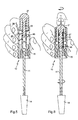
- the user holds the applicator 10 between his fingers by holding it by the gripping member 15, as illustrated in FIG. 5.
- the user can rotate the applicator member 14 on itself by pressing the control member 21, with a finger for example, as illustrated in Figure 6.
- the connecting element 22 is formed in one piece with the control member 21 and the latter rotates when the user drives it, which can hinder to some extent its rotation.
- control member 21 may be made so as not to rotate when it is pressed into the gripping member 15.
- the device represented in this figure differs from that just described on the one hand by the fact that the connecting element 22 is connected to the control member 21 by a connection which allows a free rotation of the organ 21 relative to the connecting element 22, and secondly by the fact that the connecting element 22 cooperates with the gripping member 15 so that an axial displacement of the connecting member 22 is converted into rotational movement thereof.
- the connecting element 22 comprises a skirt 34 surrounding the portion 48 of the connecting element intended to engage at least partially in the housing 23 of the rod 11.
- the skirt 34 comprises in the lower part the lugs 26 intended to cooperate with the threads 25 of the gripping member 15, the outer skirt 29 of the control member 21 being devoid of and simply covering the skirt 34 of the connecting member 22 without preventing it from rotating.
- the control member 21 comprises a ball 30 which is engaged in a cage 36 made in the upper part of the connecting element 22.
- the resilient return member 27 bears toply in the bottom of the groove formed between the skirt 34 and the portion 48, against a transverse wall 49 through which the skirt 34 connects to the portion 48.
- the connecting element 22 When the user presses on the control member 21 and that it sinks into the gripping member 15, the connecting element 22 is driven axially in displacement and the lugs 26 cooperate with the threads 25, which causes rotation of the connecting element 22.
- the ball 30 can rotate in its cage 36, which allows the control member 21 not to rotate.
- the applicator member 14 can be configured for makeup of the skin, mucous membranes or nails.
- the upper 11 comprises a portion that is engaged in a housing of the connecting element, of complementary cross section and not completely circular.
- the elastic return member 27 is disposed in the housing 23.
- the mounting of the rod 11 in the gripping member 15 could be achieved otherwise, and it is for example the mounting skirt 18 which could comprise the groove 41 and the gripping member 15 which could comprise at least the bead 17 engaged therein.
- the wiper member 3 could be made differently, for example with a block of foam, or be absent.
- the cooperating reliefs of the gripping member and the control member or the connecting element may comprise at least one groove formed in an insert inside the body of the gripping.
- the elastic return member 27 is absent.
Landscapes
- Brushes (AREA)
- Coating Apparatus (AREA)
Applications Claiming Priority (1)
| Application Number | Priority Date | Filing Date | Title |
|---|---|---|---|
| FR0451750A FR2873550B1 (fr) | 2004-07-30 | 2004-07-30 | Applicateur et dispositif de conditionnement et d'application comportant un tel applicateur. |
Publications (2)
| Publication Number | Publication Date |
|---|---|
| EP1621104A2 true EP1621104A2 (de) | 2006-02-01 |
| EP1621104A3 EP1621104A3 (de) | 2006-05-31 |
Family
ID=34947817
Family Applications (1)
| Application Number | Title | Priority Date | Filing Date |
|---|---|---|---|
| EP05300632A Withdrawn EP1621104A3 (de) | 2004-07-30 | 2005-07-29 | Applikator und Aufbewahrungs- bzw. Auftragevorrichtung mit einem solchen Applikator |
Country Status (2)
| Country | Link |
|---|---|
| EP (1) | EP1621104A3 (de) |
| FR (1) | FR2873550B1 (de) |
Cited By (3)
| Publication number | Priority date | Publication date | Assignee | Title |
|---|---|---|---|---|
| WO2007060438A3 (en) * | 2005-11-25 | 2007-09-07 | Melinda Sue Lane | Applicator |
| WO2008103796A1 (en) * | 2007-02-21 | 2008-08-28 | The Procter & Gamble Company | Cosmetic applicator with torque limiter |
| EP2172125A1 (de) * | 2008-10-03 | 2010-04-07 | Alcan Packaging Beauty Services | Rotierender Kosmetikapplikator |
Citations (4)
| Publication number | Priority date | Publication date | Assignee | Title |
|---|---|---|---|---|
| US4428388A (en) | 1981-11-06 | 1984-01-31 | Cassai Gino H | Adjustable cosmetic wand |
| US4922934A (en) | 1987-03-06 | 1990-05-08 | Roan S.P.A. | Rotary applicator device, particularly for mascara |
| US5937871A (en) | 1999-04-05 | 1999-08-17 | Clay; Mary A. | Interactive mascara brush |
| US6145514A (en) | 1999-08-31 | 2000-11-14 | Clay; Mary A. | Interactive mascara brush 2 |
Family Cites Families (4)
| Publication number | Priority date | Publication date | Assignee | Title |
|---|---|---|---|---|
| FR2664509B1 (fr) * | 1990-07-10 | 1994-04-15 | Lvmh Recherche | Dispositif applicateur pour produits liquides plus ou moins visqueux. |
| AT3160U1 (de) * | 1998-11-06 | 1999-11-25 | Kanz Gerhard Dr | Mascara - bürste |
| FR2826246A1 (fr) * | 2001-06-26 | 2002-12-27 | Oreal | Essoreur a montage simplifie |
| US6565276B1 (en) * | 2002-05-10 | 2003-05-20 | Lina Faye Howard Diaz | Electrically driven hand-held device for eyelash mascara application |
-
2004
- 2004-07-30 FR FR0451750A patent/FR2873550B1/fr not_active Expired - Fee Related
-
2005
- 2005-07-29 EP EP05300632A patent/EP1621104A3/de not_active Withdrawn
Patent Citations (4)
| Publication number | Priority date | Publication date | Assignee | Title |
|---|---|---|---|---|
| US4428388A (en) | 1981-11-06 | 1984-01-31 | Cassai Gino H | Adjustable cosmetic wand |
| US4922934A (en) | 1987-03-06 | 1990-05-08 | Roan S.P.A. | Rotary applicator device, particularly for mascara |
| US5937871A (en) | 1999-04-05 | 1999-08-17 | Clay; Mary A. | Interactive mascara brush |
| US6145514A (en) | 1999-08-31 | 2000-11-14 | Clay; Mary A. | Interactive mascara brush 2 |
Cited By (4)
| Publication number | Priority date | Publication date | Assignee | Title |
|---|---|---|---|---|
| WO2007060438A3 (en) * | 2005-11-25 | 2007-09-07 | Melinda Sue Lane | Applicator |
| WO2008103796A1 (en) * | 2007-02-21 | 2008-08-28 | The Procter & Gamble Company | Cosmetic applicator with torque limiter |
| CN101616617B (zh) * | 2007-02-21 | 2011-09-07 | 宝洁公司 | 具有扭矩限制器的化妆品施用装置 |
| EP2172125A1 (de) * | 2008-10-03 | 2010-04-07 | Alcan Packaging Beauty Services | Rotierender Kosmetikapplikator |
Also Published As
| Publication number | Publication date |
|---|---|
| FR2873550B1 (fr) | 2006-11-24 |
| EP1621104A3 (de) | 2006-05-31 |
| FR2873550A1 (fr) | 2006-02-03 |
Similar Documents
| Publication | Publication Date | Title |
|---|---|---|
| EP0931476B1 (de) | Vorrichtung zum Aufbewahren und Auftragen von pulverförmigen, flüssigen oder pastösen Produkten mit einem Kolben | |
| EP0916282B1 (de) | Vorrichtung zum Aufbewahren und Auftragen mit einem Behälter, einem ergonomischen Applikator und einem Abstreifer | |
| EP1036519B1 (de) | Auftragsvorrichtung mit Austragsspindel, die durch eine Zugfeder in ihre Ausgangslage zurück geholt wird | |
| EP1652449A2 (de) | Kit zum Schminken von Keratinfasern | |
| EP2734080B1 (de) | System zum aufbewahren und auftragen eines produkts, insbesondere eines kosmetikprodukts | |
| EP2130453B1 (de) | Vorrichtung zum Aufbewahren und Auftragen mit einem einziehbaren Anschlag | |
| EP1452111A1 (de) | Vorrichtung zum Speichern und Applizieren eines kosmetischen Produktes | |
| FR2724296A1 (fr) | Ensemble applicateur pour produit cosmetique, tel un mascara | |
| EP0859563B1 (de) | Träger für einen applikator | |
| WO2011064482A1 (fr) | Kit comprenant un dispositif applicateur de produit et son utilisation. | |
| CA1228331A (fr) | Boite a poudre de maquillage et son pinceau applicateur | |
| FR2679425A1 (fr) | Dispositif d'essorage d'une brosse ou analogue et recipient avec brosse pour le maquillage des cils, equipe de ce dispositif. | |
| EP1275322A1 (de) | Abstreifer mit vereinfachter Montage | |
| EP2938223B1 (de) | Verpackungs- und applikationssystem für ein kosmetisches produkt und verwendung davon | |
| EP1410730B1 (de) | Vorrichtung mit einem Antrieb eines Stiftes oder eines beweglichen Kolbens in einem Basisteil | |
| EP0610107A1 (de) | Applikator und Einheit zur Aufnahme und zum Auftragen von Mascara | |
| EP1174355A1 (de) | Vorrichtung zum Aufbewahren und Ausgeben eines kapillaren Produktes | |
| EP1369055B1 (de) | Applikator mit einer Stange, die mit einer Greifvorrichtung durch ein Gelenk verbunden ist | |
| FR2873550A1 (fr) | Applicateur et dispositif de conditionnement et d'application comportant un tel applicateur. | |
| FR3104390A1 (fr) | Recharge de produit cosmétique, ensemble de chargement, mécanisme de distribution et nécessaire associés | |
| EP1384416A1 (de) | Vorrichtung zum Aufbewahren und zum Auftragen eines Produktes, insbesondere eines Nagellackentferners | |
| FR2701197A1 (fr) | Applicateur de mascara et ensemble comprenant un tel applicateur et un corps de stockage du mascara. | |
| EP1570763A1 (de) | Schmink- oder Hautpflegeapplikator | |
| FR3104392A1 (fr) | Recharge de produit cosmétique, destinée à être montée de manière amovible dans une frette d’habillage, ensemble de chargement, nécessaire, dispositif et procédé de montage associé | |
| FR2968518A1 (fr) | Applicateur rotatif pour l'application d'un produit cosmetique, de maquillage ou de soin, sur cils, comportant un frein. |
Legal Events
| Date | Code | Title | Description |
|---|---|---|---|
| PUAI | Public reference made under article 153(3) epc to a published international application that has entered the european phase |
Free format text: ORIGINAL CODE: 0009012 |
|
| 17P | Request for examination filed |
Effective date: 20050807 |
|
| AK | Designated contracting states |
Kind code of ref document: A2 Designated state(s): AT BE BG CH CY CZ DE DK EE ES FI FR GB GR HU IE IS IT LI LT LU LV MC NL PL PT RO SE SI SK TR |
|
| AX | Request for extension of the european patent |
Extension state: AL BA HR MK YU |
|
| PUAL | Search report despatched |
Free format text: ORIGINAL CODE: 0009013 |
|
| AK | Designated contracting states |
Kind code of ref document: A3 Designated state(s): AT BE BG CH CY CZ DE DK EE ES FI FR GB GR HU IE IS IT LI LT LU LV MC NL PL PT RO SE SI SK TR |
|
| AX | Request for extension of the european patent |
Extension state: AL BA HR MK YU |
|
| 17Q | First examination report despatched |
Effective date: 20060807 |
|
| AKX | Designation fees paid |
Designated state(s): AT BE BG CH CY CZ DE DK EE ES FI FR GB GR HU IE IS IT LI LT LU LV MC NL PL PT RO SE SI SK TR |
|
| STAA | Information on the status of an ep patent application or granted ep patent |
Free format text: STATUS: THE APPLICATION IS DEEMED TO BE WITHDRAWN |
|
| 18D | Application deemed to be withdrawn |
Effective date: 20150203 |