EP1621301A1 - Vorrichtung zum automatischen Schneiden von Brot in Scheiben - Google Patents
Vorrichtung zum automatischen Schneiden von Brot in Scheiben Download PDFInfo
- Publication number
- EP1621301A1 EP1621301A1 EP04077179A EP04077179A EP1621301A1 EP 1621301 A1 EP1621301 A1 EP 1621301A1 EP 04077179 A EP04077179 A EP 04077179A EP 04077179 A EP04077179 A EP 04077179A EP 1621301 A1 EP1621301 A1 EP 1621301A1
- Authority
- EP
- European Patent Office
- Prior art keywords
- bread
- frame
- compartment
- blades
- cutting
- Prior art date
- Legal status (The legal status is an assumption and is not a legal conclusion. Google has not performed a legal analysis and makes no representation as to the accuracy of the status listed.)
- Withdrawn
Links
- 235000008429 bread Nutrition 0.000 title claims abstract description 82
- 238000005520 cutting process Methods 0.000 claims abstract description 28
- 238000006073 displacement reaction Methods 0.000 claims description 4
- 101100008050 Caenorhabditis elegans cut-6 gene Proteins 0.000 description 1
- 230000001419 dependent effect Effects 0.000 description 1
- 230000009977 dual effect Effects 0.000 description 1
- 238000000034 method Methods 0.000 description 1
Images


Classifications
-
- B—PERFORMING OPERATIONS; TRANSPORTING
- B26—HAND CUTTING TOOLS; CUTTING; SEVERING
- B26D—CUTTING; DETAILS COMMON TO MACHINES FOR PERFORATING, PUNCHING, CUTTING-OUT, STAMPING-OUT OR SEVERING
- B26D1/00—Cutting through work characterised by the nature or movement of the cutting member or particular materials not otherwise provided for; Apparatus or machines therefor; Cutting members therefor
- B26D1/01—Cutting through work characterised by the nature or movement of the cutting member or particular materials not otherwise provided for; Apparatus or machines therefor; Cutting members therefor involving a cutting member which does not travel with the work
- B26D1/547—Cutting through work characterised by the nature or movement of the cutting member or particular materials not otherwise provided for; Apparatus or machines therefor; Cutting members therefor involving a cutting member which does not travel with the work having a wire-like cutting member
- B26D1/553—Cutting through work characterised by the nature or movement of the cutting member or particular materials not otherwise provided for; Apparatus or machines therefor; Cutting members therefor involving a cutting member which does not travel with the work having a wire-like cutting member with a plurality of wire-like cutting members
-
- B—PERFORMING OPERATIONS; TRANSPORTING
- B26—HAND CUTTING TOOLS; CUTTING; SEVERING
- B26D—CUTTING; DETAILS COMMON TO MACHINES FOR PERFORATING, PUNCHING, CUTTING-OUT, STAMPING-OUT OR SEVERING
- B26D7/00—Details of apparatus for cutting, cutting-out, stamping-out, punching, perforating, or severing by means other than cutting
- B26D7/27—Means for performing other operations combined with cutting
- B26D7/32—Means for performing other operations combined with cutting for conveying or stacking cut product
- B26D2007/327—Means for performing other operations combined with cutting for conveying or stacking cut product the cut products being slices of bread
-
- B—PERFORMING OPERATIONS; TRANSPORTING
- B26—HAND CUTTING TOOLS; CUTTING; SEVERING
- B26D—CUTTING; DETAILS COMMON TO MACHINES FOR PERFORATING, PUNCHING, CUTTING-OUT, STAMPING-OUT OR SEVERING
- B26D7/00—Details of apparatus for cutting, cutting-out, stamping-out, punching, perforating, or severing by means other than cutting
- B26D7/01—Means for holding or positioning work
Definitions
- the present invention relates to an automated cutting device sliced breads.
- Automated cutting devices for sliced breads are well known. They are found in most bakeries and also in supermarkets. These devices, or automatic bread slicers according to the state of the art, operate according to the following principle: The user of the device introduces the bread he wants to cut into slices by placing it in a loading compartment provided for this purpose . This compartment is traditionally arranged between a bread driving element and a set of parallel blades for slicing said bread. The user then starts the device by engaging the switch provided for this purpose, which causes the reciprocating movement of the blades and translational movement transversely to the direction of the blades of the drive element of the bread. The bread is then moved by this drive element towards the blades and cutting begins when it comes in contact with them. The user retrieves his sliced bread in a compartment disposed of unloading the side of the blades opposite to that where is placed the load compartment of the bread in the device. This user then only has to pack the cut bread.
- This type of automated cutting device for sliced bread poses at least two problems.
- the first is that it requires a movement mechanism of the relatively complex bread driving element in that it comprises a system of rods, guides and propulsion which tends during its operation to cause significant vibrations of the device frame.
- the second problem with this type of device is that it requires both a first bread loading compartment disposed on one side of all the cutting blades and a second separate bread unloading compartment disposed on the other side of the cutting blade assembly. This results in a size and therefore a large size of the device due to the necessary presence of these two compartments.
- an automated slice cake cutter comprising a frame, a bread loading compartment in the device, which compartment comprises a first bread support member and a second bread support member.
- bread in this compartment the device further comprising a set of bread cutting blades arranged substantially parallel to each other and arranged to be reciprocated reciprocating movement, the set of blades being mounted in a movable frame arranged to be moved by a moving means between a first position in which the bread to be cut can be loaded into the above-mentioned compartment and a second position in which the bread cut by said blades can be extracted from said compartment.
- the movable frame carrying the blade assembly according to the invention is arranged to be moved between a first position in which the bread to be cut can be loaded into the loading compartment and a second position in which the cut bread can be extracted from the compartment, no more drive element of the bread is necessary and the movement mechanism of this element which is associated therewith according to the state of the art therefore also disappears, which notably avoids the problem of vibration of the aforementioned frame consecutive to the action of the displacement mechanism in question.
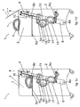
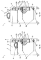
- FIGS. 1a to 1d, 2a to 2d and 3a to 3f attached representing schematic views in vertical section of a device according to said invention.
- FIGS. 1a to 1d and 2a to 2d and 3a to 3f show a device 1 for automated cutting of a sliced bread 6 comprising a frame 2, a compartment 3 for loading bread into the device, which compartment 3 comprises a first element 3a bread support 6 as well as in the case of Figures 1a to 1d and 2a to 2d a second element 3b retaining bread 6 in the compartment 3 disposed on one side of the latter and in the case of figures 3a to 3f, two such second elements 3b disposed on either side of the compartment 3.
- the device 1 further comprises an assembly 4 of bread cutting blades 6 arranged substantially parallel to each other and arranged to be driven by reciprocating back and forth.
- the assembly 4 of blades is mounted in a frame 5 movable relative to the frame 2 and arranged to be moved between a first position A shown in Figures 1a, 1b, 2a, 2b, 3a and 3e in which the bread 6 to be cut can to be loaded in the compartment 3 when a valve 7 giving access to this compartment is raised and a second position B shown in FIGS. 1c, 1d, 2c, 2d, 3c, 3d and 3f wherein the bread 6 once cut by said set of blades 4 can be removed from the compartment 3, the valve 7 then being raised again, the latter remaining for security reasons lowered during the bread cutting operation 6 to isolate the compartment 3 of the user of the device during this operation.
- valve 7 could be arranged not on the top of the device as shown in the figures but, in the case of the embodiments of the invention illustrated in FIGS. 1a to 1d and 2a to 2d, of FIG. side of the device opposite the bread retaining member 6 3b.
- the support elements 3a and retaining 3b of the bread 6 consist of a plate of a rigid material in which are formed slots in which the blades of the blade assembly 4 can be moved during the cutting operation bread 6.
- the device 1 illustrated further comprises a push-rod element 10 pivotally mounted on the frame 5, arranged in the form of a comb between the teeth of which the blades of the blade assembly 4 pass and provided with a resilient means such that a spring (not illustrated) arranged so that this element pushes bread 10 exerts pressure on the bread 6 during its cutting by the set of blades 4, so as to avoid jolts of said bread 6 in the compartment 3 during said cut.
- a push-rod element 10 pivotally mounted on the frame 5, arranged in the form of a comb between the teeth of which the blades of the blade assembly 4 pass and provided with a resilient means such that a spring (not illustrated) arranged so that this element pushes bread 10 exerts pressure on the bread 6 during its cutting by the set of blades 4, so as to avoid jolts of said bread 6 in the compartment 3 during said cut.
- FIGS. 1a to 1d illustrate an embodiment of the invention according to which the frame 5 is pivotally mounted on a first fixed axis 8a relative to the frame 2, to be moved between its first A and its second B positions according to a rotational movement and according to which embodiment, the frame of the displacement means 5 consists of a hydraulic or pneumatic cylinder 9a fixed to the frame 2.
- the frame 5 When the frame 5 has reached its second B position and the bread 6 cut in slices was extracted from the device 1, said frame 5 is returned to its first A position before another bread 6 to be cut can be introduced into the compartment 3 of the device 1.
- Figures 2a to 2d illustrate another embodiment of the invention according to which the frame 5 is arranged to slide on two rails 8b fixed relative to the frame 2, for example by means of rollers (not shown) circulating on the rails 8b, to be moved between its first A and its second B positions in a translational movement.
- the means for moving the frame 5 consists of a first motor 9b.
- This first motor 9b can, as shown in Figures 2a to 2d be secured to the frame 5 or on the contrary could also be attached to the frame 2 and cause the displacement of the frame 5 for example by means of a rack or a toothed belt connecting the first motor 9b in the frame 5 by any known system, such as gears or pulleys.
- FIGS. 3a to 3f show a variant of the embodiment of the invention shown in FIGS. 1a to 1d, in which a roll 6 can be introduced into the compartment 3 of the device 1 once the frame 5 has reached its second B position, without it being necessary to bring back said frame 5 in a first A position different from said second B position reached at the end of cutting the previous bread, as shown in Figures 3e and 3f.
- a roll 6 can be introduced into the compartment 3 of the device 1 once the frame 5 has reached its second B position, without it being necessary to bring back said frame 5 in a first A position different from said second B position reached at the end of cutting the previous bread, as shown in Figures 3e and 3f.
- a second motor 11 having a rotary axis is mounted on the frame 5 and is arranged to print a reciprocating motion to the blade assembly 4 by means of a belt 17 which can, via a first pulley (not shown) mounted on the rotary shaft of the second motor 11, drive a second pulley 12 in a rotational movement about a second axis 13 integral with the frame 5, on which pulley 12 is pivotally mounted about a third axis 14 fixed to said pulley 12 and eccentrically relative thereto, a connecting rod 15 pivotally connected to the blade assembly 4 by a fourth axis 16 integral with said blade assembly 4.
- the frame 5 When operating a device according to the invention, the frame 5 is first disposed in its position A illustrated in Figures 1a, 1b, 2a, 2b, 3a, 3e. A bread slice 6 is introduced into the device once the valve 7 raised as illustrated in Figures 1a, 2a, 3a and 3e. the valve 7 is then closed again and the operation of cutting the bread is engaged by pressing a button (not shown) controlling the energy supply of the moving means of the frame 5 and the set of blades 4. The frame 5 is then moved in the direction of the horizontal arrow shown in Figures 1b, 2b, 3b and 3f so that the set of 4 blades cut the bread 6, which is achieved when the frame 5 arrives in its position B illustrated in Figures 1c, 2c and 3c. The valve 7 can then be raised and the cut 6 bread extracted compartment 3 as shown in Figures 1d, 2d and 3d.
- the invention by eliminating the need for the presence of a drive element of a bread through the blade assembly of a device according to the state of the art offers the dual advantage of both eliminating the nuisance in terms of vibration inherent in such a drive element during its operation as described above and to allow the realization of a device for automatically cutting slices of bread a much smaller footprint than that of a device according to the state of the art which must include a compartment for unloading a cut bread separate from that of loading said bread to be cut, unlike the device according to the invention.
Landscapes
- Life Sciences & Earth Sciences (AREA)
- Forests & Forestry (AREA)
- Engineering & Computer Science (AREA)
- Mechanical Engineering (AREA)
- Food-Manufacturing Devices (AREA)
Priority Applications (1)
| Application Number | Priority Date | Filing Date | Title |
|---|---|---|---|
| EP04077179A EP1621301A1 (de) | 2004-07-29 | 2004-07-29 | Vorrichtung zum automatischen Schneiden von Brot in Scheiben |
Applications Claiming Priority (1)
| Application Number | Priority Date | Filing Date | Title |
|---|---|---|---|
| EP04077179A EP1621301A1 (de) | 2004-07-29 | 2004-07-29 | Vorrichtung zum automatischen Schneiden von Brot in Scheiben |
Publications (1)
| Publication Number | Publication Date |
|---|---|
| EP1621301A1 true EP1621301A1 (de) | 2006-02-01 |
Family
ID=34928415
Family Applications (1)
| Application Number | Title | Priority Date | Filing Date |
|---|---|---|---|
| EP04077179A Withdrawn EP1621301A1 (de) | 2004-07-29 | 2004-07-29 | Vorrichtung zum automatischen Schneiden von Brot in Scheiben |
Country Status (1)
| Country | Link |
|---|---|
| EP (1) | EP1621301A1 (de) |
Cited By (2)
| Publication number | Priority date | Publication date | Assignee | Title |
|---|---|---|---|---|
| CN107718086A (zh) * | 2016-06-24 | 2018-02-23 | 惠安县灿鑫新材料科技有限公司 | 一种自动切片装置 |
| US11224985B2 (en) | 2018-09-11 | 2022-01-18 | Marmon Foodservice Technologies, Inc. | Slicer |
Citations (5)
| Publication number | Priority date | Publication date | Assignee | Title |
|---|---|---|---|---|
| GB527741A (en) * | 1939-04-19 | 1940-10-15 | Berkel & Parnall Mach Mfg Co | Improvements relating to slicing machines |
| GB536278A (en) * | 1939-12-28 | 1941-05-08 | Berkel Patent Nv | Improvements relating to slicing machines |
| US2290169A (en) * | 1936-06-20 | 1942-07-21 | Us Slicing Machine Co | Bread slicing machine |
| US2789606A (en) * | 1954-10-15 | 1957-04-23 | Oliver Machinery Co | Bread slicing machine |
| FR2176320A5 (en) * | 1972-03-17 | 1973-10-26 | Devianne Sarl Ets | Bread slicing machine - smaller and faster than prior apt |
-
2004
- 2004-07-29 EP EP04077179A patent/EP1621301A1/de not_active Withdrawn
Patent Citations (5)
| Publication number | Priority date | Publication date | Assignee | Title |
|---|---|---|---|---|
| US2290169A (en) * | 1936-06-20 | 1942-07-21 | Us Slicing Machine Co | Bread slicing machine |
| GB527741A (en) * | 1939-04-19 | 1940-10-15 | Berkel & Parnall Mach Mfg Co | Improvements relating to slicing machines |
| GB536278A (en) * | 1939-12-28 | 1941-05-08 | Berkel Patent Nv | Improvements relating to slicing machines |
| US2789606A (en) * | 1954-10-15 | 1957-04-23 | Oliver Machinery Co | Bread slicing machine |
| FR2176320A5 (en) * | 1972-03-17 | 1973-10-26 | Devianne Sarl Ets | Bread slicing machine - smaller and faster than prior apt |
Cited By (2)
| Publication number | Priority date | Publication date | Assignee | Title |
|---|---|---|---|---|
| CN107718086A (zh) * | 2016-06-24 | 2018-02-23 | 惠安县灿鑫新材料科技有限公司 | 一种自动切片装置 |
| US11224985B2 (en) | 2018-09-11 | 2022-01-18 | Marmon Foodservice Technologies, Inc. | Slicer |
Similar Documents
| Publication | Publication Date | Title |
|---|---|---|
| EP2746003B1 (de) | Gerät zum Schneiden von Lebensmitteln in Scheiben, Stifte, Würfel oder Fäden | |
| EP2934833A1 (de) | Lebensmittelzerkleinerungseinrichtung mit einer oszillierenden bewegung und einem sicherheitssteuerungsmittel | |
| EP1621301A1 (de) | Vorrichtung zum automatischen Schneiden von Brot in Scheiben | |
| BE1028272B1 (fr) | Trancheuse de pain oblique | |
| EP2941334A1 (de) | Vorrichtung zum schneiden von lebensmitteln mit einem kompakten übertragungssystem | |
| BE1024083B1 (fr) | Trancheuse de pain avec un moyen de pression et un organe de poussée | |
| EP2941161B1 (de) | Lebensmittelzubereitungsvorrichtung mit einer halterung zur anbringung eines abnehmbaren reinigungszubehörs | |
| EP3967465B1 (de) | Brotschneidemaschine mit einer halterung für die brotscheiben | |
| BE1028600B1 (fr) | Trancheuse de pain avec un couvercle mobile | |
| EP0030061B1 (de) | Brotschneidemaschine | |
| BE1029561B1 (fr) | Trancheuse à pain avec une surface d’appui mobile pour le pain coupé | |
| BE1027928B1 (fr) | Machine pour découper automatiquement un pain avec un capteur de blocage | |
| BE1031571B1 (fr) | Trancheuse de pain | |
| EP3950243B1 (de) | Brotschneidemaschine und schieber für brotschneidemaschine | |
| BE1025568B1 (fr) | Machine et procédé pour couper et ensacher un pain | |
| BE1024338B1 (fr) | Machine verticale à couper un pain avec une lame circulaire entraînée par un moteur indépendant | |
| BE1022515B1 (fr) | Machine pour couper automatiquement un pain en tranches avec support frontal | |
| EP3331673B1 (de) | Vorrichtung für das schneiden von brot mit einer stützfläche für das brot, die einen schlitz für das messer aufweist | |
| FR2536960A1 (fr) | Dispositif de detourage automatique des bords de tranches de pain et produits similaires | |
| WO2010037404A1 (fr) | Dispositif de découpe automatisée de pains | |
| EP1757414A1 (de) | Automatische Brotschneidemaschine | |
| WO2002100613A1 (fr) | Dispositif ainsi que procede d'ejection dynamique de dechets pour machine de decoupe de materiaux en feuilles |
Legal Events
| Date | Code | Title | Description |
|---|---|---|---|
| PUAI | Public reference made under article 153(3) epc to a published international application that has entered the european phase |
Free format text: ORIGINAL CODE: 0009012 |
|
| AK | Designated contracting states |
Kind code of ref document: A1 Designated state(s): AT BE BG CH CY CZ DE DK EE ES FI FR GB GR HU IE IT LI LU MC NL PL PT RO SE SI SK TR |
|
| AX | Request for extension of the european patent |
Extension state: AL HR LT LV MK |
|
| AKX | Designation fees paid | ||
| REG | Reference to a national code |
Ref country code: DE Ref legal event code: 8566 |
|
| STAA | Information on the status of an ep patent application or granted ep patent |
Free format text: STATUS: THE APPLICATION IS DEEMED TO BE WITHDRAWN |
|
| 18D | Application deemed to be withdrawn |
Effective date: 20060802 |