EP1621325B1 - Vorrichtung zum Abdichten von Reifen - Google Patents
Vorrichtung zum Abdichten von Reifen Download PDFInfo
- Publication number
- EP1621325B1 EP1621325B1 EP05105032A EP05105032A EP1621325B1 EP 1621325 B1 EP1621325 B1 EP 1621325B1 EP 05105032 A EP05105032 A EP 05105032A EP 05105032 A EP05105032 A EP 05105032A EP 1621325 B1 EP1621325 B1 EP 1621325B1
- Authority
- EP
- European Patent Office
- Prior art keywords
- compressed air
- air line
- container
- filter element
- gas outlet
- Prior art date
- Legal status (The legal status is an assumption and is not a legal conclusion. Google has not performed a legal analysis and makes no representation as to the accuracy of the status listed.)
- Expired - Lifetime
Links
Images

Classifications
-
- B—PERFORMING OPERATIONS; TRANSPORTING
- B29—WORKING OF PLASTICS; WORKING OF SUBSTANCES IN A PLASTIC STATE IN GENERAL
- B29C—SHAPING OR JOINING OF PLASTICS; SHAPING OF MATERIAL IN A PLASTIC STATE, NOT OTHERWISE PROVIDED FOR; AFTER-TREATMENT OF THE SHAPED PRODUCTS, e.g. REPAIRING
- B29C73/00—Repairing of articles made from plastics or substances in a plastic state, e.g. of articles shaped or produced by using techniques covered by this subclass or subclass B29D
- B29C73/16—Auto-repairing or self-sealing arrangements or agents
- B29C73/166—Devices or methods for introducing sealing compositions into articles
-
- B—PERFORMING OPERATIONS; TRANSPORTING
- B29—WORKING OF PLASTICS; WORKING OF SUBSTANCES IN A PLASTIC STATE IN GENERAL
- B29L—INDEXING SCHEME ASSOCIATED WITH SUBCLASS B29C, RELATING TO PARTICULAR ARTICLES
- B29L2030/00—Pneumatic or solid tyres or parts thereof
Definitions
- the invention relates to a device for sealing inflatable objects, in particular tires, with a container containing a sealant, which is connectable via a first compressed air line with a gas pressure source and one end of a second compressed air line to a sealed object, wherein the first compressed air line and the second compressed air line communicate with each other via the container interior.
- Such devices for sealing tires have long been z. B. from the DE 195 45 935 A1 , of the DE 198 46 451 A1 and the WO 02/066236 A1 known.
- the sealant used in such a tire sealing device is generally based on natural rubber latex blends.
- the sealant is produced in a time-consuming process to minimize contaminants in the sealant.
- the sealing means which is transferred by means of the device via the second compressed air line and the tire valve in the tire, the tire valve is not clogged early and thus further overfinging of sealant and inflation of the tire is impossible.
- the complex manufacturing process of the sealant requires a great deal of time and expense.
- the invention has for its object to provide a device for sealing inflatable objects, in particular tires, in which a sealant is used, which is to produce with little effort.
- the object is achieved in that the device includes a filter element through which the sealant flows before it emerges from the end of the second compressed air line.
- the advantage achieved with the invention is to be seen in particular in that the device can be operated with a sealant that can be produced in a simple manner. This is due to the fact that in the manufacture of the sealant impurities in the sealant needs to be respected only to a much lesser extent than before, since impurities in the sealant are either retained or crushed by the filter element in an application of the device. Thus, the danger is effectively prevented that the impurities contained in the sealant clog the tire valve early.
- a further advantage of the invention is that the remaining components of the device do not need to be changed (for example, no gas pressure source in the form of a compressor having a higher capacity is required to remove the impurities in the sealant) Filter element to press). This makes it possible to retrofit devices already in use with a filter element and convert in the future to cost-effective sealant.
- the filter element can be arranged at any point between the outlet of the container interior and the end of the second compressed air line (or the transition into the tire interior), for example in the bottleneck of the container. Further, it is possible to introduce the filter element in an adapter, through which the second compressed air line is extended and which is then part of the second compressed air line. It is also possible to introduce the filter element in the tire valve, which is then part of the second compressed air line in the context of the invention. According to a preferred embodiment of the invention according to claim 2, however, the filter element covers at least the flow cross section of the second compressed air line. The advantage of this development is the fact that the filter element in the second compressed air line can be attached easily and simultaneously effective.
- the first compressed air line includes a gas inlet element and the second compressed air line, a gas outlet to which a compressed air hose is connectable, wherein the elements are in communication via the container interior.
- the gas inlet element and the gas outlet element are components of a removal unit, which is releasably connectable to the sealant container.
- At least part of the filter element covers the flow cross-section of the gas outlet element.
- the gas inlet element and the gas outlet element extend coaxially at their ends facing the sealant container.
- the filter element in the area of o.g. Ends of the gas inlet element and gas outlet arranged and formed as an annular disc, which is pushed onto the end of the gas inlet element and covers the flow cross-section of the end of the gas outlet.
- the filter element is arranged in the region of the ends of the gas inlet element and the gas outlet element and designed as a cup which is pushed onto the end of the gas inlet element and covers the flow cross-section of the ends of gas inlet element and gas outlet element.
- the development according to claim 8 has the same advantages as the development according to claim 7.
- the development is achieved by the development according to claim 8, that the filter element in the region of the end of the gas outlet by appropriate training of the cup has a large cross-section, so that with the help of the filter element particularly effective impurities can be retained.
- a cup it is also possible to use a tube with which the flow cross-section of the end of the gas outlet element is covered.
- the filter element is designed as a sieve.
- a sieve is simple, e.g. made of plastic by injection molding, can be produced.
- the sieve has a mesh size between 50 .mu.m and 1.5 mm, preferably between 150 .mu.m and 1 mm.
- the filter element made of corrosion-resistant material.
- it is made of corrosion-resistant metal or plastic.
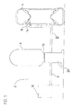
- FIG. 1 shows a device 2 for sealing tires 4.
- the device comprises a sealing means containing container 6, which is connected via a first compressed air line 8 to a gas pressure source in the form of a compressor 10. Furthermore, the device has a second compressed air line 12, one end of which is connected to the container 6 and whose other end 14 can be connected to the tire valve 16.
- the first compressed air line 8 and the second compressed air line 12 terminate in a removal unit 20, which is connected to the container 6, and communicate with each other via the interior of the container 6.
- Such a device 2 is used in a manner known per se as follows: With the aid of the compressor 10, compressed air is transferred via the first compressed air line 8 into the interior of the container 6. Starting from the interior of the container 6, a mixture of compressed air and sealing means via the second compressed air line 12 and the tire valve 16 is transferred into the interior of the tire 4. In this way, a damaged tire 4 can be sealed with the sealant and inflated at the same time.
- the device 2 contains over the components mentioned so far addition (in the FIG. 1 not shown) filter element through which the sealant located in the container 6 flows before it exits from the end 14 of the second compressed air line in the tire valve 16 and from there into the tire 4.
- the filter element can be introduced into the flow of sealant at any point (for example into the bottle neck 18 of the container 6).
- the filter element is preferably introduced into the device 2 in such a way that it covers at least the flow cross-section of the second compressed-air line 12 as far as possible (for more details see FIG. Figures 2 and 3 ).
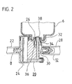
- FIG. 2 shows a removal unit 20 in cross section.
- the first compressed air line 8, which is guided on the compressor 10 (s. FIG. 1 ) consists of a first compressed air hose 22 and a gas inlet element 24, which is part of the extraction unit 20. At one end of the gas inlet element 24, the first compressed air hose 22 is attached. The other end 26 of the gas inlet element 24 faces the interior of the container 6.
- the second compressed air line 12 consists of a second compressed air hose 28, and a gas outlet element 30, which is also part of the extraction unit 20.
- the second compressed air hose 28 is connected at one end to the gas outlet member 30 and the other end is guided on the tire valve 16 (s. FIG. 1 ).
- the end 32 of the gas outlet element 30 faces the interior of the container 6.
- the ends 26 and 32 which face the interior of the container 6 are arranged coaxially with one another, the end 26 of the gas inlet element being coaxially surrounded by the end 32 of the gas outlet element.
- the compressed air supplied by the compressor 10 is guided via the gas inlet element 24 into the interior of the container 6, and a mixture of sealing agent and compressed air via the gas outlet 30 and the second compressed air hose 28 in the tire 4 transferred.
- the mixture of compressed air and sealing means which is guided through the second compressed air line 12 in the tire 4, is guided by a filter element 34, the Flow cross section of the second compressed air line 12 at least largely covers.
- the filter element 34 in which in the FIG. 2 shown embodiment designed as a cup 34.
- This cup 34 is placed with its opening 36 down on the end 26 of the gas inlet element 24 such that the bottom 38 of the cup 34 covers the outlet opening at the end 26 of the gas inlet element 24.
- the clear opening 36 of the cup 34 corresponds in size approximately to the flow cross-section at the end 32 of the gas outlet element 30, which faces the interior of the container 6. This ensures that in the region of the opening 36, the side wall of the cup 34 rests against the inner wall of the end 32 of the gas outlet element, so that the side wall of the cup 34 effectively covers the flow cross section of the gas outlet element 30.
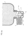
- FIG. 3 shows that in the FIG. 2 shown in cross-section filter element 34 in the form of a cup 34 in detail.
- the cup 34 is made of corrosion-resistant material and can, for. B. made of plastic in injection molding.
- the cup 34 contains in its side wall (s. FIG. 3a ) and in its bottom 38 (s. FIG. 3b ) Openings 40, so that the cup 34 is formed as a sieve 34.
- the clear width of the openings 40 is located both in the X and in the Y direction (see FIGS. 3a and 3b ) between 50 ⁇ m and 1.5 mm, preferably between 150 ⁇ m and 500 ⁇ m.
- filter element 34 it is also possible, in which in the FIG. 3 shown filter element 34 to dispense with the bottom 38, so that the filter element 34 has the shape of a tube with a conically extending side wall.
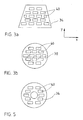
- FIG. 4 shows a removal unit 20, already from the WO 02/066 236 A1 is known there is described in detail. With respect to the operation of this extraction unit 20 per se, reference is therefore made to this document.
- the extraction unit 20 with its gas inlet element 24 and its gas outlet element 30 has a piston 42.
- the container 6 facing the end 26 of the gas inlet element 24 is integrated.
- the piston 42 includes at the end 26 an annular collar 44 on which an annular filter element in the form of a screen 34 is supported, which is pushed onto the end 26 of the gas inlet element 24
- the operation of the extraction unit 20 is as follows: With the aid of a (in the FIG. 4a Compressor is not shown by the gas inlet element 24 compressed air under the piston 42, which then moves upward, as shown in the FIG. 4b is shown. In this movement, the screen 34 is taken up, since it is supported on the annular collar 44 of the piston 42. As a result of the upward movement of the upper end of the piston 42 pierces the seal 46 of the container 6. Further, the compressed air supplied by the compressor passes through the upper end 26 of the gas inlet element 24 into the interior of the container 6, as well as through the line in of the FIG. 4b is indicated.
- the container 6 From the container 6 flows a mixture of sealing agent and compressed air via the annular channel 32, which forms the upper end 32 of the gas outlet 30, in the Gasauslasselement 30 and from there (via a compressed air hose, not shown) in a tire to be sealed 4 (s. FIG. 1 ).
- the upper end 32 of the gas outlet member 30 coaxially surrounds the upper end 26 of the gas inlet member 24.
- the screen 34 is in the position of the piston 42, which in the FIG. 4b is shown, in the upper end 32 of the gas outlet element 30, that it at least largely covers its flow cross-section.
- the mixture of sealing agent and compressed air from the interior of the container 6 thus first flows through the sieve 34 before it is transferred into the tire to be sealed.
- FIG. 5 shows that in the FIGS. 4a and 4b shown sieve 34 in plan view.
- the screen 34 has the shape of an annular disc, which may consist of corrosion-resistant metal or plastic.
- the screen 34 contains openings 40, which have the same size, as already in connection with the FIG. 3 has been explained.
Landscapes
- Engineering & Computer Science (AREA)
- Mechanical Engineering (AREA)
- Filtering Of Dispersed Particles In Gases (AREA)
- Mechanical Sealing (AREA)
- Arrangements For Transmission Of Measured Signals (AREA)
- Gasket Seals (AREA)
- Tires In General (AREA)
Description
- Die Erfindung betrifft eine Vorrichtung zum Abdichten aufblasbarer Gegenstände, insbesondere Reifen, mit einem ein Abdichtmittel enthaltenden Behälter, der über eine erste Druckluftleitung mit einer Gasdruckquelle und über ein Ende einer zweiten Druckluftleitung an einen abzudichtenden Gegenstand anschließbar ist, wobei die erste Druckluftleitung und die zweite Druckluftleitung über den Behälterinnenraum miteinander in Verbindung stehen.
- Derartige Vorrichtungen zum Abdichten von Reifen sind seit langem z. B. aus der
DE 195 45 935 A1 , derDE 198 46 451 A1 und derWO 02/066236 A1 - Der Erfindung liegt die Aufgabe zugrunde, eine Vorrichtung zum Abdichten von aufblasbaren Gegenständen, insbesondere Reifen zu schaffen, bei der ein Dichtmittel verwendbar ist, das mit geringem Aufwand herzustellen ist.
- Gemäß dem kennzeichnenden Merkmal des Anspruchs 1 wird die Aufgabe dadurch gelöst, dass die Vorrichtung ein Filterelement enthält, durch das das Dichtmittel fließt, bevor es aus dem Ende der zweiten Druckluftleitung austritt.
- Der mit der Erfindung erzielte Vorteil ist insbesondere darin zu sehen, dass die Vorrichtung mit einem Dichtmittel betrieben werden kann, das auf einfache Art und Weise herstellbar ist. Dies ist darauf zurückzuführen, dass bei der Herstellung des Dichtmittels auf Verunreinigungen im Dichtmittel nur noch in einem erheblich geringeren Umfang als früher geachtet zu werden braucht, da Verunreinigungen in dem Dichtmittel bei einer Anwendung der Vorrichtung durch das Filterelement entweder zurückgehalten oder zerkleinert werden. Somit ist der Gefahr wirksam vorgebeugt, dass die in dem Dichtmittel enthaltenen Verunreinigungen das Reifenventil frühzeitig verstopfen. Ein weiterer Vorteil der Erfindung ist darin zu sehen, dass die übrigen Bestandteile der Vorrichtung nicht verändert zu werden brauchen (es ist z. B. keine Gasdruckquelle in Form eines Kompressors notwendig, der eine höhere Leistung aufweist, um die Verunreinigungen in dem Dichtmittel durch das Filterelement zu drücken). Hierdurch wird es möglich, bereits im Einsatz befindliche Vorrichtungen mit einem Filterelement nachzurüsten und in Zukunft auf kostengünstige Dichtmittel umzustellen.
- Das Filterelement kann an sich an beliebiger Stelle zwischen dem Ausgang des Behälterinnenraums und dem Ende der zweiten Druckluftleitung (bzw. dem Übergang in den Reifeninnenraum) angeordnet sein, z.B. im Flaschenhals des Behälters. Ferner ist es möglich, das Filterelement in einen Adapter einzubringen, durch den die zweite Druckluftleitung verlängert wird und der dann Bestandteil der zweiten Druckluftleitung ist. Es ist ebenfalls möglich, das Filterelement in das Reifenventil einzubringen, das dann im Sinne der Erfindung zum Bestandteil der zweiten Druckluftleitung wird. Gemäß einer bevorzugten Weiterbildung der Erfindung nach Anspruch 2 deckt das Filterelement jedoch zumindest den Fließquerschnitt der zweiten Druckluftleitung ab. Der Vorteil dieser Weiterbildung ist darin zu sehen, dass das Filterelement in der zweiten Druckluftleitung einfach und gleichzeitig wirkungsvoll angebracht werden kann.
- Gemäß einer Weiterbildung der Erfindung nach Anspruch 3 enthält die erste Druckluftleitung ein Gaseinlasselement und die zweite Druckluftleitung ein Gasauslasselement, an das ein Druckluftschlauch anschließbar ist, wobei die Elemente über den Behälterinnenraum miteinander in Verbindung stehen. Der Vorteil dieser Weiterbildung ist darin zu sehen, dass das Gaseinlasselement und das Gasauslasselement an ihrem einen Ende auf besonders einfache Art und Weise mit Druckluftschläuchen verbindbar sind und an ihrem jeweiligen anderen Ende auf besonders einfache Art und Weise über den Behälterinnenraum miteinander in Verbindung gebracht werden können.
- Gemäß einer Weiterbildung nach Anspruch 4 sind das Gaseinlasselement und das Gasauslasselement Bestandteile einer Entnahmeeinheit, die mit dem Dichtmittelbehälter lösbar verbindbar ist. EinVorteil dieser Weiterbildung ist darin zu sehen, dass der Dichtmittelbehälter getrennt von der Entnahmeeinheit gelagert werden kann. Ein weiterer Vorteil dieser Weiterbildung ist darin zu sehen, dass nach einer Entleerung eines alten Dichtmittelbehälters dieser von der Entnahmeeinheit gelöst und ein neuer Dichtmittelbehälter mit der Entnahmeeinheit verbunden werden kann. Vorzugsweise werden die Dichtmittelbehälter an der Entnahmeeinheit verschraubt.
- Gemäß einer Weiterbildung der Erfindung nach Anspruch 5 deckt zumindest ein Teil des Filterelementes den Fließquerschnitt des Gasauslasselementes ab. Der Vorteil dieser Weiterbildung ist darin zu sehen, dass das Fileterelement auf besonders einfache Art und Weise in dem Fließquerschnitt des Gasauslasselementes eingebracht werden kann.
- Gemäß einer Weiterbildung der Erfindung nach Anspruch 6 verlaufen des Gaseinlasselement und das Gasauslasselement an ihren dem Dichtmittelbehälter zugewandeten Enden koaxial. Ein Vorteil dieser Weiterbildung ist darin zu sehen, dass das Gaseinlasselement und das Gasauslasselement besonders raumsparend in einer kleinen Entnahmeeinheit angeordnet werden können. Weitere Vorteile dieser Weiterbildung werden im Zusammenhang mit den Weiterbildungen gemäß den Ansprüchen 7 und 8 deutlich.
- Gemäß einer Weiterbildung der Erfindung nach Anspruch 7 ist das Filterelement im Bereich der o.g. Enden von Gaseinlasselement und Gasauslasselement angeordnet und als Ringscheibe ausgebildet, die auf das Ende des Gaseinlasselementes geschoben ist und den Fließquerschnitt des Endes des Gasauslasselementes abdeckt. Ein Vorteil dieser Weiterbildung ist darin zu sehen, dass das Filterelement auf besonders einfache Art und Weise in den Fließquerschnitt des Endes des Gasauslasselementes eingebracht werden kann.
- Gemäß einer Weiterbildung der Erfindung nach Anspruch 8 ist das Filterelement im Bereich der Enden des Gaseinlasselementes und des Gasauslasselementes angeordnet und als Becher ausgebildet, der auf das Ende des Gaseinlasselementes geschoben ist und den Fließquerschnitt der Enden von Gaseinlasselement und Gasauslasselement abdeckt. Die Weiterbildung gemäß Anspruch 8 weist die gleichen Vorteile auf wie die Weiterbildung gemäß Anspruch 7. Darüber hinaus wird durch die Weiterbildung gemäß Anspruch 8 der Vorteil erreicht, dass das Filterelement im Bereich des Endes des Gasauslasselementes durch entsprechende Ausbildung des Bechers einen großen Wirkungsquerschnitt aufweist, so dass mit Hilfe des Filterelementes besonders wirkungsvoll Verunreinigungen zurückgehalten werden können. Anstelle eines Bechers kann auch eine Röhre verwendet werden, mit der der Fließquerschnitt des Endes des Gasauslasselement abgedeckt wird.
- Gemäß einer Weiterbildung der Erfindung nach Anspruch 9 ist das Filterelement als Sieb ausgebildet. Der Vorteil dieser Weiterbildung ist darin zu sehen, dass ein Sieb einfach, z.B. aus Kunststoff in Spritzgußtechnik, hergestellt werden kann.
- Gemäß einer Weiterbildung der Erfindung nach Anspruch 10 weist das Sieb eine Maschenweite zwischen 50µm und 1,5 mm, vorzugsweise zwischen 150 µm und 1 mm, auf. Der Vorteil dieser Weiterbildung ist darin zu sehen, dass mit einem derartigen Sieb einerseits große Verunreinigungen wirkungsvoll zurückgehalten werden können und andererseits kleinere Verunreinigungen durch das Sieb wirkungsvoll zerkleinert werden können. Somit ist sichergestellt, dass die zerkleinerten Verunreinigungen das Reifenventil im Anwendungsfall der Vorrichtung nicht verstopfen.
- Gemäß einer Weiterbildung der Erfindung nach Anspruch 11 besteht das Filterelement aus korrosionsbeständigem Material. Vorzugsweise besteht es aus korrosionsbeständigem Metall oder aus Kunststoff. Der Vorteil dieser Weiterbildung ist darin zu sehen, dass das Filterelement durch Korrosion nicht beschädigt werden kann und somit über einen langen Zeitraum seine Funktion aufrechterhalten bleibt.
- Ein Ausführungsbeispiel und weitere Vorteile der Erfindung werden im Zusammenhang mit den nachstehenden Figuren erläutert, darin zeigt:
- Fig. 1
- eine Vorrichtung zum Abdichten eines Reifens in schematischer Darstellung,
- Fig. 2
- eine Entnahmeeinheit im Querschnitt,
- Fig. 3
- ein Sieb
- Fig. 4
- eine Entnahmeeinheit im Querschnitt
- Fig. 5
- ein Sieb.
-
Figur 1 zeigt eine Vorrichtung 2 zum Abdichten von Reifen 4. Die Vorrichtung enthält einen ein Abdichtmittel enthaltenden Behälter 6, der über eine erste Druckluftleitung 8 mit einer Gasdruckquelle in Form eines Kompressors 10 verbunden ist. Ferner weist die Vorrichtung eine zweite Druckluftleitung 12 auf, deren eines Ende mit dem Behälter 6 verbunden ist und deren anderes Ende 14 an das Reifenventil 16 angeschlossen werden kann. Die erste Druckluftleitung 8 und die zweite Druckluftleitung 12 enden in einer Entnahmeeinheit 20, die mit dem Behälter 6 verbunden ist, und stehen über den Innenraum des Behälters 6 miteinander in Verbindung. Eine derartige Vorrichtung 2 wird in an sich bekannter Art und Weise wie folgt genutzt: Mit Hilfe des Kompressors 10 wird Druckluft über die erste Druckluftleitung 8 in den Innenraum des Behälters 6 überführt. Ausgehend von dem Innenraum des Behälters 6 wird ein Gemisch aus Druckluft und Abdichtmittel über die zweite Druckluftleitung 12 und das Reifenventil 16 in den Innenraum des Reifens 4 überführt. Auf diese Art und Weise kann ein beschädigter Reifen 4 mit dem Dichtmittel abgedichtet und gleichzeitig aufgepumpt werden. - Die Vorrichtung 2 enthält über die bisher genannten Bestandteile hinaus ein (in der
Figur 1 nicht gezeigtes) Filterelement, durch das das in dem Behälter 6 befindliche Dichtmittel fließt, bevor es aus dem Ende 14 der zweiten Druckluftleitung in das Reifenventil 16 und von dort in den Reifen 4 austritt. Das Filterelement kann an beliebiger Stelle in den Dichtmittelfluss eingebracht werden (z. B. in den Flaschenhals 18 des Behälters 6). Bevorzugt wird das Filterelement jedoch derart in die Vorrichtung 2 eingebracht, dass es zumindest den Fließquerschnitt der zweiten Druckluftleitung 12 weitestgehend abdeckt (Näheres s.Figuren 2 und3 ). -
Figur 2 zeigt eine Entnahmeeinheit 20 im Querschnitt. Die erste Druckluftleitung 8, die auf den Kompressor 10 geführt wird (s.Figur 1 ) besteht aus einem ersten Druckluftschlauch 22 und einem Gaseinlasselement 24, das Bestandteil der Entnahmeeinheit 20 ist. An einem Ende des Gaseinlasselementes 24 ist der erste Druckluftschlauch 22 befestigt. Das andere Ende 26 des Gaseinlasselementes 24 ist dem Innenraum des Behälters 6 zugewandt. - Die zweite Druckluftleitung 12 besteht aus einem zweiten Druckluftschlauch 28, und einem Gasauslasselement 30, das ebenfalls Bestandteil der Entnahmeeinheit 20 ist. Der zweite Druckluftschlauch 28 ist an einem Ende an das Gasauslasselement 30 angeschlossen und das andere Ende wird der auf das Reifenventil 16 geführt wird (s.
Figur 1 ). Das Ende 32 des Gasauslasselementes 30 ist dem Innenraum des Behälters 6 zugewandt. Die Enden 26 und 32, die dem Innenraum des Behälters 6 zugewandt sind, sind koaxial zueinander angeordnet, wobei das Ende 26 des Gaseinlasselementes von dem Ende 32 des Gasauslasselementes koaxial umfasst wird. - Bei einer Anwendung der Vorrichtung 2 (s.
Figur 1 ) wird die von dem Kompressor 10 gelieferte Druckluft über das Gaseinlasselement 24 in den Innenraum des Behälters 6 geführt, und ein Gemisch aus Abdichtmittel und Druckluft über das Gasauslasselement 30 und den zweiten Druckluftschlauch 28 in den Reifen 4 überführt. - Das Gemisch aus Druckluft und Abdichtmittel, welches durch die zweite Druckluftleitung 12 in den Reifen 4 geführt wird, wird durch ein Filterelement 34 geführt, das den Fließquerschnitt der zweiten Druckluftleitung 12 zumindest weitgehend abdeckt. Hierzu ist das Filterelement 34 bei dem in der
Figur 2 gezeigten Ausführungsbeispiel als Becher 34 ausgebildet. Dieser Becher 34 wird mit seiner Öffnung 36 nach unten derart auf das Ende 26 des Gaseinlasselementes 24 aufgesetzt, dass der Boden 38 des Bechers 34 die Austrittsöffnung am Ende 26 des Gaseinlasselementes 24 abdeckt. Die lichte Öffnung 36 des Bechers 34 entspricht in ihrer Größe in etwa dem Fließquerschnitt am Ende 32 des Gasauslasselementes 30, das dem Innenraum des Behälters 6 zugewandt ist. Hierdurch wird erreicht, dass im Bereich der Öffnung 36 die Seitenwand des Bechers 34 an der Innenwand des Endes 32 des Gasauslasselementes anliegt, so dass die Seitenwand des Bechers 34 den Fließquerschnitt des Gasauslasselementes 30 wirksam abdeckt. -
Figur 3 zeigt das in derFigur 2 im Querschnitt gezeigte Filterelement 34 in Form eines Bechers 34 im Detail. Der Becher 34 besteht aus korrosionsbeständigem Material und kann z. B. aus Kunststoff in Spritzgusstechnik hergestellt werden. Der Becher 34 enthält in seiner Seitenwand (s.Figur 3a ) und in seinem Boden 38 (s.Figur 3b ) Durchbrechungen 40, so dass der Becher 34 als Sieb 34 ausgebildet. Die lichte Breite der Durchbrechungen 40 liegt sowohl in der X- als auch in der Y-Richtung (s. Koordinatenkreuz neben denFiguren 3a und 3b ) zwischen 50 µm und 1,5 mm, vorzugsweise zwischen 150 µm und 500 µm. - Es ist ebenfalls möglich, bei dem in der
Figur 3 gezeigten Filterelement 34 auf den Boden 38 zu verzichten, so dass das Filterelement 34 die Form einer Röhre mit einer konisch verlaufenden Seitenwand aufweist. -
Figur 4 zeigt eine Entnahmeeinheit 20, die bereits aus derWO 02/066 236 A1 - Die Funktionsweise der Entnahmeeinheit 20 ist wie folgt: Mit Hilfe eines (in der
Figur 4a nicht gezeigten) Kompressors wird durch das Gaseinlasselement 24 Druckluft unter den Kolben 42 geführt, der sich daraufhin nach oben bewegt, wie es in derFigur 4b gezeigt ist. Bei dieser Bewegung wird das Sieb 34 nach oben mitgenommen, da es sich auf dem ringförmigen Kragen 44 des Kolbens 42 abstützt. Infolge der Bewegung nach oben durchsticht das obere Ende des Kolbens 42 das Siegel 46 des Behälters 6. Ferner gelangt die von dem Kompressor gelieferte Druckluft durch das obere Ende 26 des Gaseinlasselementes 24 in den Innenraum des Behälters 6, so wie es auch durch die Zeile in derFigur 4b angedeutet ist. - Aus dem Behälter 6 fließt ein Gemisch aus Abdichtmittel und Druckluft über den Ringkanal 32, der das obere Ende 32 des Gasauslasselementes 30 bildet, in das Gasauslasselement 30 und von dort (über einen nicht gezeigten) Druckluftschlauch in einen abzudichtenden Reifen 4 (s.
Figur 1 ). Das obere Ende 32 des Gasauslasselementes 30 umfasst das obere Ende 26 des Gaseinlasselementes 24 koaxial. Das Sieb 34 liegt in der Position des Kolbens 42, die in derFigur 4b gezeigt ist, derart in dem oberen Ende 32 des Gasauslasselementes 30, dass es dessen Fließquerschnitt zumindest weitestgehend abdeckt. Das Gemisch aus Abdichtmittel und Druckluft aus dem Innenraum des Behälters 6 fließt also zunächst durch das Sieb 34, bevor es in den abzudichtenden Reifen überführt wird. -
Figur 5 zeigt das in denFiguren 4a und4b gezeigte Sieb 34 in Draufsicht. Das Sieb 34 weist die Form einer Ringscheibe auf, die aus korrosionsbeständigem Metall oder Kunststoff bestehen kann. Das Sieb 34 enthält Durchbrechungen 40, die die gleiche Größe aufweisen, wie es bereits im Zusammenhang mit derFigur 3 erläutert worden ist. -
- 2
- Vorrichtung
- 4
- Reifen
- 6
- Behälter
- 8
- erste Druckluftleitung
- 10
- Kompressor
- 12
- zweite Druckluftleitung
- 14
- Ende der zweiten Druckluftleitung
- 16
- Reifenventil
- 18
- Flaschenhals
- 20
- Entnahmeeinheit
- 22
- erster Druckluftschlauch
- 24
- Gaseinlasselement
- 26
- Ende des Gaseinlasselementes
- 28
- zweiter Druckluftschlauch
- 30
- Gasauslasselement
- 32
- Ende des Gasauslasselementes
- 34
- Filterelement
- 36
- Öffnung
- 38
- Boden
- 40
- Durchbrechungen
- 42
- Kolben
- 44
- Kragen
- 46
- Siegel
Claims (11)
- Vorrichtung (2) zum Abdichten aufblasbarer Gegenstände, insbesondere Reifen (4), mit einem ein Abdichtmittel enthaltenden Behälter (6), der über eine erste Druckluftleitung (8) mit einer Gasdruckquelle (10) und über ein Ende (14) einer zweiten Druckluftleitung (12) an einen abzudichtenden Gegenstand anschließbar ist, wobei die erste Druckluftleitung (8) und die zweite Druckluftleitung (12) über den Behälterinnenraum miteinander in Verbindung stehen, dadurch gekennzeichnet, dass die Vorrichtung (2) ein Filterelement (34) enthält, durch das das Dichtmittel fließt, bevor es aus dem Ende (14) der zweiten Druckluftleitung (12) austritt.
- Vorrichtung (2) nach Anspruch 1, dadurch gekennzeichnet, dass das Filterelement (34) zumindest den Fließquerschnitt der zweiten Druckluftleitung (12) zumindest weitestgehend abdeckt.
- Vorrichtung (2) nach einem der Ansprüche 1, dadurch gekennzeichnet, dass die erste Druckluftleitung (8) ein Gaseinlasselement (24) und die zweite Druckluftleitung (12) ein Gasauslasselement (30), an das ein Druckluftschlauch (28) anschließbar ist, enthält, wobei die Elemente (24, 30) über den Behälterinnenraum miteinander in Verbindung stehen.
- Vorrichtung (2) nach Anspruch 3, dadurch gekennzeichnet, dass das Gaseinlasselement (24) und das Gasauslasselement (30) Bestandteile einer Entnahmeeinheit (20) sind, die mit dem Behälter (6) lösbar verbindbar ist.
- Vorrichtung (2) nach einem der Ansprüche 3 bis 4, dadurch gekennzeichnet, dass zumindest ein Teil des Filterelementes (34) den Fließquerschnitt des Gasauslasselementes (30) abdeckt.
- Vorrichtung (2) nach einem der Ansprüche 3 bis 5, dadurch gekennzeichnet, dass das Gaseinlasselement (24) und das Gasauslasselement (30) an ihren dem Behälter (6) zugewandten Enden (26, 32) koaxial verlaufen.
- Vorrichtung (2) nach Anspruch 6, dadurch gekennzeichnet, dass das Filterelement (34) im Bereich der Enden (26, 32) angeordnet ist und als Ringscheibe (34) ausgebildet ist, die auf den das Ende (26) des Gaseinlasselementes (24) geschoben ist und den Fließquerschnitt des Endes (32) des Gasauslasselementes (30) zumindest weitestgehend abdeckt.
- Vorrichtung (2) nach Anspruch 6, dadurch gekennzeichnet, dass das Filterelement (34) im Bereich der Enden (26, 32) angeordnet ist und als Becher (34) ausgebildet ist, der auf das Ende (26) des Gaseinlasselementes (24) geschoben ist und den Fließquerschnitt der Enden (26, 32) abdeckt.
- Vorrichtung (2) nach einem der Ansprüche 1 bis 8, dadurch gekennzeichnet, dass das Filterelement (34) als Sieb (34) ausgebildet ist.
- Vorrichtung (2) nach Anspruch 9, dadurch gekennzeichnet, dass das Sieb (34) eine Maschenweite zwischen 50 um und 1,5 mm aufweist.
- Vorrichtung (2) nach einem der Ansprüche 1 bis 10, dadurch gekennzeichnet, dass das Filterelement (34) aus korrosionsbeständigem Material besteht.
Applications Claiming Priority (1)
| Application Number | Priority Date | Filing Date | Title |
|---|---|---|---|
| DE102004036917A DE102004036917A1 (de) | 2004-07-29 | 2004-07-29 | Vorrichtung zum Abdichten von Reifen |
Publications (2)
| Publication Number | Publication Date |
|---|---|
| EP1621325A1 EP1621325A1 (de) | 2006-02-01 |
| EP1621325B1 true EP1621325B1 (de) | 2008-10-08 |
Family
ID=35058344
Family Applications (1)
| Application Number | Title | Priority Date | Filing Date |
|---|---|---|---|
| EP05105032A Expired - Lifetime EP1621325B1 (de) | 2004-07-29 | 2005-06-09 | Vorrichtung zum Abdichten von Reifen |
Country Status (3)
| Country | Link |
|---|---|
| EP (1) | EP1621325B1 (de) |
| AT (1) | ATE410296T1 (de) |
| DE (2) | DE102004036917A1 (de) |
Families Citing this family (4)
| Publication number | Priority date | Publication date | Assignee | Title |
|---|---|---|---|---|
| DE102006053245A1 (de) * | 2006-11-11 | 2008-05-15 | Continental Aktiengesellschaft | Kompressoreinheit |
| DE102007026776A1 (de) * | 2007-06-09 | 2008-12-11 | Continental Aktiengesellschaft | Reifenabdichtvorrichtung |
| DE102019217775A1 (de) | 2019-11-19 | 2021-05-20 | Continental Reifen Deutschland Gmbh | Vorrichtung zum Transportieren von Druckluft und/oder Dichtmittel in einen Fahrzeugluftreifen und tragbares/transportables System zum Abdichten und Aufpumpen von Fahrzeugluftreifen |
| EP4261023A1 (de) * | 2022-04-06 | 2023-10-18 | Sumitomo Rubber Industries, Ltd. | Mischvorrichtung, flascheneinheit und punktionsreparaturkit |
Family Cites Families (4)
| Publication number | Priority date | Publication date | Assignee | Title |
|---|---|---|---|---|
| DE19846451C5 (de) * | 1998-10-08 | 2018-08-23 | Sumitomo Rubber Industries Ltd. | Vorrichtung zum Abdichten aufblasbarer Gegenstände, insbesondere Reifen |
| JP2002104424A (ja) * | 2000-09-28 | 2002-04-10 | Yoshino Kogyosho Co Ltd | 交換用フィルターを取り付けた液補充用容器 |
| DE60104970T2 (de) * | 2000-12-28 | 2005-08-25 | Col-Ven S.A., Guadalupe Norte | Druckgesteuerte Dreiwegeventilvorrichtung |
| DE10253445A1 (de) * | 2002-11-16 | 2004-06-03 | Adam Opel Ag | Verfahren und Vorrichtung zum Abdichten und Aufpumpen von Reifen bei Pannen sowie Dichtmittelbehälter als auch Adapter hierfür |
-
2004
- 2004-07-29 DE DE102004036917A patent/DE102004036917A1/de not_active Withdrawn
-
2005
- 2005-06-09 DE DE502005005589T patent/DE502005005589D1/de not_active Expired - Lifetime
- 2005-06-09 AT AT05105032T patent/ATE410296T1/de active
- 2005-06-09 EP EP05105032A patent/EP1621325B1/de not_active Expired - Lifetime
Also Published As
| Publication number | Publication date |
|---|---|
| ATE410296T1 (de) | 2008-10-15 |
| DE502005005589D1 (de) | 2008-11-20 |
| EP1621325A1 (de) | 2006-02-01 |
| DE102004036917A1 (de) | 2006-03-23 |
Similar Documents
| Publication | Publication Date | Title |
|---|---|---|
| EP1121324B2 (de) | Abdichtvorrichtung | |
| EP0298227B1 (de) | Verfahren zum Befüllen und anschliessenden Verschweissen eines Behälters sowie Vorrichtung und Behälter zur Durchführung dieses Verfahrens | |
| DE10253445A1 (de) | Verfahren und Vorrichtung zum Abdichten und Aufpumpen von Reifen bei Pannen sowie Dichtmittelbehälter als auch Adapter hierfür | |
| DE10012684A1 (de) | Einrichtung zur Rückgewinnung eines inerten Gases | |
| WO2002066236A1 (de) | Gerät zum abdichten und aufpumpen eines aufblasbaren objekts | |
| EP4061624B1 (de) | Vorrichtung zum transportieren von druckluft und/oder dichtmittel in einen fahrzeugluftreifen und tragbares/transportables system zum abdichten und aufpumpen von fahrzeugluftreifen | |
| DE69911548T2 (de) | Abfüllventil | |
| DE102005024731A1 (de) | Füllgerät zum Abfüllen von Trinkflüssigkeit | |
| DE2138064A1 (de) | Biegsame Folge vorrichtung für Behälter | |
| DE1536884A1 (de) | Filtervorrichtung | |
| EP1621325B1 (de) | Vorrichtung zum Abdichten von Reifen | |
| DE19964584B4 (de) | Vorrichtung zum Abdichten und Aufpumpen von Reifen | |
| DE9101471U1 (de) | Auslaufkonus eines Behälters, z.B. eines Silos | |
| DE2945440C2 (de) | Waschanlage für Scheiben von Kraftfahrzeugen | |
| DE102004002399A1 (de) | Bremszylinder | |
| DE602004010815T2 (de) | Fluidproduktabgabekopf und dessen verwendung | |
| WO2000061257A1 (de) | Kartusche und vorrichtung zum aufbereiten von flüssigkeiten | |
| DE2127651C3 (de) | Zerstäubervorrichtung | |
| EP0088148A2 (de) | Filter | |
| EP0867656B1 (de) | Druckgaskapsel | |
| EP0633190A1 (de) | Verfahren und Vorrichtung zum Befüllen von Aerosolbehältern | |
| DE102022101078A1 (de) | Vorrichtung zum bedarfsweisen aufblasen oder reparieren von aufblasbaren artikeln oder erzeugnissen, insbesondere von reifen, vorzugsweise fahrzeugreifen | |
| EP0593861B1 (de) | Ventilsackfüllmaschine | |
| DE1486090C (de) | Verfahren zum Einfüllen von pulver formigem Gut in oben offene Behalter | |
| DE1456110C (de) | Luftkissenfahrzeug |
Legal Events
| Date | Code | Title | Description |
|---|---|---|---|
| PUAI | Public reference made under article 153(3) epc to a published international application that has entered the european phase |
Free format text: ORIGINAL CODE: 0009012 |
|
| AK | Designated contracting states |
Kind code of ref document: A1 Designated state(s): AT BE BG CH CY CZ DE DK EE ES FI FR GB GR HU IE IS IT LI LT LU MC NL PL PT RO SE SI SK TR |
|
| AX | Request for extension of the european patent |
Extension state: AL BA HR LV MK YU |
|
| 17P | Request for examination filed |
Effective date: 20060801 |
|
| AKX | Designation fees paid |
Designated state(s): AT BE BG CH CY CZ DE DK EE ES FI FR GB GR HU IE IS IT LI LT LU MC NL PL PT RO SE SI SK TR |
|
| AXX | Extension fees paid |
Extension state: BA Payment date: 20060801 Extension state: YU Payment date: 20060801 Extension state: HR Payment date: 20060801 Extension state: MK Payment date: 20060801 Extension state: AL Payment date: 20060801 Extension state: LV Payment date: 20060801 |
|
| 17Q | First examination report despatched |
Effective date: 20071115 |
|
| RIC1 | Information provided on ipc code assigned before grant |
Ipc: B60C 17/02 20060101ALI20080116BHEP Ipc: B29D 30/00 20060101ALI20080116BHEP Ipc: B29C 73/16 20060101AFI20080116BHEP |
|
| GRAP | Despatch of communication of intention to grant a patent |
Free format text: ORIGINAL CODE: EPIDOSNIGR1 |
|
| GRAS | Grant fee paid |
Free format text: ORIGINAL CODE: EPIDOSNIGR3 |
|
| GRAA | (expected) grant |
Free format text: ORIGINAL CODE: 0009210 |
|
| AK | Designated contracting states |
Kind code of ref document: B1 Designated state(s): AT BE BG CH CY CZ DE DK EE ES FI FR GB GR HU IE IS IT LI LT LU MC NL PL PT RO SE SI SK TR |
|
| AX | Request for extension of the european patent |
Extension state: AL BA HR LV MK YU |
|
| REG | Reference to a national code |
Ref country code: GB Ref legal event code: FG4D Free format text: NOT ENGLISH |
|
| REG | Reference to a national code |
Ref country code: CH Ref legal event code: EP |
|
| REG | Reference to a national code |
Ref country code: IE Ref legal event code: FG4D Free format text: LANGUAGE OF EP DOCUMENT: GERMAN |
|
| REF | Corresponds to: |
Ref document number: 502005005589 Country of ref document: DE Date of ref document: 20081120 Kind code of ref document: P |
|
| PG25 | Lapsed in a contracting state [announced via postgrant information from national office to epo] |
Ref country code: SI Free format text: LAPSE BECAUSE OF FAILURE TO SUBMIT A TRANSLATION OF THE DESCRIPTION OR TO PAY THE FEE WITHIN THE PRESCRIBED TIME-LIMIT Effective date: 20081008 |
|
| NLV1 | Nl: lapsed or annulled due to failure to fulfill the requirements of art. 29p and 29m of the patents act | ||
| PG25 | Lapsed in a contracting state [announced via postgrant information from national office to epo] |
Ref country code: ES Free format text: LAPSE BECAUSE OF FAILURE TO SUBMIT A TRANSLATION OF THE DESCRIPTION OR TO PAY THE FEE WITHIN THE PRESCRIBED TIME-LIMIT Effective date: 20090119 Ref country code: BG Free format text: LAPSE BECAUSE OF FAILURE TO SUBMIT A TRANSLATION OF THE DESCRIPTION OR TO PAY THE FEE WITHIN THE PRESCRIBED TIME-LIMIT Effective date: 20090108 Ref country code: LT Free format text: LAPSE BECAUSE OF FAILURE TO SUBMIT A TRANSLATION OF THE DESCRIPTION OR TO PAY THE FEE WITHIN THE PRESCRIBED TIME-LIMIT Effective date: 20081008 |
|
| PG25 | Lapsed in a contracting state [announced via postgrant information from national office to epo] |
Ref country code: PL Free format text: LAPSE BECAUSE OF FAILURE TO SUBMIT A TRANSLATION OF THE DESCRIPTION OR TO PAY THE FEE WITHIN THE PRESCRIBED TIME-LIMIT Effective date: 20081008 Ref country code: IS Free format text: LAPSE BECAUSE OF FAILURE TO SUBMIT A TRANSLATION OF THE DESCRIPTION OR TO PAY THE FEE WITHIN THE PRESCRIBED TIME-LIMIT Effective date: 20090208 Ref country code: PT Free format text: LAPSE BECAUSE OF FAILURE TO SUBMIT A TRANSLATION OF THE DESCRIPTION OR TO PAY THE FEE WITHIN THE PRESCRIBED TIME-LIMIT Effective date: 20090218 Ref country code: NL Free format text: LAPSE BECAUSE OF FAILURE TO SUBMIT A TRANSLATION OF THE DESCRIPTION OR TO PAY THE FEE WITHIN THE PRESCRIBED TIME-LIMIT Effective date: 20081008 Ref country code: FI Free format text: LAPSE BECAUSE OF FAILURE TO SUBMIT A TRANSLATION OF THE DESCRIPTION OR TO PAY THE FEE WITHIN THE PRESCRIBED TIME-LIMIT Effective date: 20081008 |
|
| REG | Reference to a national code |
Ref country code: IE Ref legal event code: FD4D |
|
| PG25 | Lapsed in a contracting state [announced via postgrant information from national office to epo] |
Ref country code: DK Free format text: LAPSE BECAUSE OF FAILURE TO SUBMIT A TRANSLATION OF THE DESCRIPTION OR TO PAY THE FEE WITHIN THE PRESCRIBED TIME-LIMIT Effective date: 20081008 Ref country code: EE Free format text: LAPSE BECAUSE OF FAILURE TO SUBMIT A TRANSLATION OF THE DESCRIPTION OR TO PAY THE FEE WITHIN THE PRESCRIBED TIME-LIMIT Effective date: 20081008 Ref country code: IE Free format text: LAPSE BECAUSE OF FAILURE TO SUBMIT A TRANSLATION OF THE DESCRIPTION OR TO PAY THE FEE WITHIN THE PRESCRIBED TIME-LIMIT Effective date: 20081008 Ref country code: RO Free format text: LAPSE BECAUSE OF FAILURE TO SUBMIT A TRANSLATION OF THE DESCRIPTION OR TO PAY THE FEE WITHIN THE PRESCRIBED TIME-LIMIT Effective date: 20081008 |
|
| PLBE | No opposition filed within time limit |
Free format text: ORIGINAL CODE: 0009261 |
|
| STAA | Information on the status of an ep patent application or granted ep patent |
Free format text: STATUS: NO OPPOSITION FILED WITHIN TIME LIMIT |
|
| PG25 | Lapsed in a contracting state [announced via postgrant information from national office to epo] |
Ref country code: IT Free format text: LAPSE BECAUSE OF FAILURE TO SUBMIT A TRANSLATION OF THE DESCRIPTION OR TO PAY THE FEE WITHIN THE PRESCRIBED TIME-LIMIT Effective date: 20081008 Ref country code: SE Free format text: LAPSE BECAUSE OF FAILURE TO SUBMIT A TRANSLATION OF THE DESCRIPTION OR TO PAY THE FEE WITHIN THE PRESCRIBED TIME-LIMIT Effective date: 20090108 Ref country code: CZ Free format text: LAPSE BECAUSE OF FAILURE TO SUBMIT A TRANSLATION OF THE DESCRIPTION OR TO PAY THE FEE WITHIN THE PRESCRIBED TIME-LIMIT Effective date: 20081008 |
|
| 26N | No opposition filed |
Effective date: 20090709 |
|
| PG25 | Lapsed in a contracting state [announced via postgrant information from national office to epo] |
Ref country code: SK Free format text: LAPSE BECAUSE OF FAILURE TO SUBMIT A TRANSLATION OF THE DESCRIPTION OR TO PAY THE FEE WITHIN THE PRESCRIBED TIME-LIMIT Effective date: 20081008 |
|
| BERE | Be: lapsed |
Owner name: CONTINENTAL A.G. Effective date: 20090630 |
|
| PG25 | Lapsed in a contracting state [announced via postgrant information from national office to epo] |
Ref country code: MC Free format text: LAPSE BECAUSE OF NON-PAYMENT OF DUE FEES Effective date: 20090630 |
|
| REG | Reference to a national code |
Ref country code: CH Ref legal event code: PL |
|
| PG25 | Lapsed in a contracting state [announced via postgrant information from national office to epo] |
Ref country code: CH Free format text: LAPSE BECAUSE OF NON-PAYMENT OF DUE FEES Effective date: 20090630 Ref country code: LI Free format text: LAPSE BECAUSE OF NON-PAYMENT OF DUE FEES Effective date: 20090630 |
|
| PG25 | Lapsed in a contracting state [announced via postgrant information from national office to epo] |
Ref country code: BE Free format text: LAPSE BECAUSE OF NON-PAYMENT OF DUE FEES Effective date: 20090630 |
|
| PG25 | Lapsed in a contracting state [announced via postgrant information from national office to epo] |
Ref country code: GR Free format text: LAPSE BECAUSE OF FAILURE TO SUBMIT A TRANSLATION OF THE DESCRIPTION OR TO PAY THE FEE WITHIN THE PRESCRIBED TIME-LIMIT Effective date: 20090109 |
|
| REG | Reference to a national code |
Ref country code: GB Ref legal event code: 732E Free format text: REGISTERED BETWEEN 20110310 AND 20110316 |
|
| PG25 | Lapsed in a contracting state [announced via postgrant information from national office to epo] |
Ref country code: LU Free format text: LAPSE BECAUSE OF NON-PAYMENT OF DUE FEES Effective date: 20090609 |
|
| PG25 | Lapsed in a contracting state [announced via postgrant information from national office to epo] |
Ref country code: HU Free format text: LAPSE BECAUSE OF FAILURE TO SUBMIT A TRANSLATION OF THE DESCRIPTION OR TO PAY THE FEE WITHIN THE PRESCRIBED TIME-LIMIT Effective date: 20090409 |
|
| PG25 | Lapsed in a contracting state [announced via postgrant information from national office to epo] |
Ref country code: CY Free format text: LAPSE BECAUSE OF FAILURE TO SUBMIT A TRANSLATION OF THE DESCRIPTION OR TO PAY THE FEE WITHIN THE PRESCRIBED TIME-LIMIT Effective date: 20081008 |
|
| REG | Reference to a national code |
Ref country code: FR Ref legal event code: PLFP Year of fee payment: 11 |
|
| PGFP | Annual fee paid to national office [announced via postgrant information from national office to epo] |
Ref country code: GB Payment date: 20150618 Year of fee payment: 11 Ref country code: TR Payment date: 20150526 Year of fee payment: 11 |
|
| PGFP | Annual fee paid to national office [announced via postgrant information from national office to epo] |
Ref country code: AT Payment date: 20150619 Year of fee payment: 11 Ref country code: FR Payment date: 20150619 Year of fee payment: 11 |
|
| REG | Reference to a national code |
Ref country code: AT Ref legal event code: MM01 Ref document number: 410296 Country of ref document: AT Kind code of ref document: T Effective date: 20160609 |
|
| GBPC | Gb: european patent ceased through non-payment of renewal fee |
Effective date: 20160609 |
|
| REG | Reference to a national code |
Ref country code: FR Ref legal event code: ST Effective date: 20170228 |
|
| PG25 | Lapsed in a contracting state [announced via postgrant information from national office to epo] |
Ref country code: FR Free format text: LAPSE BECAUSE OF NON-PAYMENT OF DUE FEES Effective date: 20160630 |
|
| PG25 | Lapsed in a contracting state [announced via postgrant information from national office to epo] |
Ref country code: AT Free format text: LAPSE BECAUSE OF NON-PAYMENT OF DUE FEES Effective date: 20160609 Ref country code: GB Free format text: LAPSE BECAUSE OF NON-PAYMENT OF DUE FEES Effective date: 20160609 |
|
| PGFP | Annual fee paid to national office [announced via postgrant information from national office to epo] |
Ref country code: DE Payment date: 20210630 Year of fee payment: 17 |
|
| PG25 | Lapsed in a contracting state [announced via postgrant information from national office to epo] |
Ref country code: TR Free format text: LAPSE BECAUSE OF NON-PAYMENT OF DUE FEES Effective date: 20160609 |
|
| REG | Reference to a national code |
Ref country code: DE Ref legal event code: R119 Ref document number: 502005005589 Country of ref document: DE |
|
| PG25 | Lapsed in a contracting state [announced via postgrant information from national office to epo] |
Ref country code: DE Free format text: LAPSE BECAUSE OF NON-PAYMENT OF DUE FEES Effective date: 20230103 |