EP1621376A2 - Dispositif de décharge de frigorigène - Google Patents
Dispositif de décharge de frigorigène Download PDFInfo
- Publication number
- EP1621376A2 EP1621376A2 EP20050015090 EP05015090A EP1621376A2 EP 1621376 A2 EP1621376 A2 EP 1621376A2 EP 20050015090 EP20050015090 EP 20050015090 EP 05015090 A EP05015090 A EP 05015090A EP 1621376 A2 EP1621376 A2 EP 1621376A2
- Authority
- EP
- European Patent Office
- Prior art keywords
- thin film
- refrigerant
- relief device
- pressure
- piercing rod
- Prior art date
- Legal status (The legal status is an assumption and is not a legal conclusion. Google has not performed a legal analysis and makes no representation as to the accuracy of the status listed.)
- Granted
Links
Images






Classifications
-
- F—MECHANICAL ENGINEERING; LIGHTING; HEATING; WEAPONS; BLASTING
- F25—REFRIGERATION OR COOLING; COMBINED HEATING AND REFRIGERATION SYSTEMS; HEAT PUMP SYSTEMS; MANUFACTURE OR STORAGE OF ICE; LIQUEFACTION SOLIDIFICATION OF GASES
- F25B—REFRIGERATION MACHINES, PLANTS OR SYSTEMS; COMBINED HEATING AND REFRIGERATION SYSTEMS; HEAT PUMP SYSTEMS
- F25B49/00—Arrangement or mounting of control or safety devices
- F25B49/005—Arrangement or mounting of control or safety devices of safety devices
-
- B—PERFORMING OPERATIONS; TRANSPORTING
- B60—VEHICLES IN GENERAL
- B60H—ARRANGEMENTS OF HEATING, COOLING, VENTILATING OR OTHER AIR-TREATING DEVICES SPECIALLY ADAPTED FOR PASSENGER OR GOODS SPACES OF VEHICLES
- B60H1/00—Heating, cooling or ventilating devices
- B60H1/00642—Control systems or circuits; Control members or indication devices for heating, cooling or ventilating devices
- B60H1/00978—Control systems or circuits characterised by failure of detection or safety means; Diagnostic methods
-
- F—MECHANICAL ENGINEERING; LIGHTING; HEATING; WEAPONS; BLASTING
- F16—ENGINEERING ELEMENTS AND UNITS; GENERAL MEASURES FOR PRODUCING AND MAINTAINING EFFECTIVE FUNCTIONING OF MACHINES OR INSTALLATIONS; THERMAL INSULATION IN GENERAL
- F16K—VALVES; TAPS; COCKS; ACTUATING-FLOATS; DEVICES FOR VENTING OR AERATING
- F16K13/00—Other constructional types of cut-off apparatus; Arrangements for cutting-off
- F16K13/04—Other constructional types of cut-off apparatus; Arrangements for cutting-off with a breakable closure member
-
- F—MECHANICAL ENGINEERING; LIGHTING; HEATING; WEAPONS; BLASTING
- F16—ENGINEERING ELEMENTS AND UNITS; GENERAL MEASURES FOR PRODUCING AND MAINTAINING EFFECTIVE FUNCTIONING OF MACHINES OR INSTALLATIONS; THERMAL INSULATION IN GENERAL
- F16K—VALVES; TAPS; COCKS; ACTUATING-FLOATS; DEVICES FOR VENTING OR AERATING
- F16K17/00—Safety valves; Equalising valves, e.g. pressure relief valves
- F16K17/02—Safety valves; Equalising valves, e.g. pressure relief valves opening on surplus pressure on one side; closing on insufficient pressure on one side
- F16K17/14—Safety valves; Equalising valves, e.g. pressure relief valves opening on surplus pressure on one side; closing on insufficient pressure on one side with fracturing member
- F16K17/16—Safety valves; Equalising valves, e.g. pressure relief valves opening on surplus pressure on one side; closing on insufficient pressure on one side with fracturing member with fracturing diaphragm ; Rupture discs
- F16K17/1606—Safety valves; Equalising valves, e.g. pressure relief valves opening on surplus pressure on one side; closing on insufficient pressure on one side with fracturing member with fracturing diaphragm ; Rupture discs of the reverse-buckling-type
- F16K17/1613—Safety valves; Equalising valves, e.g. pressure relief valves opening on surplus pressure on one side; closing on insufficient pressure on one side with fracturing member with fracturing diaphragm ; Rupture discs of the reverse-buckling-type with additional cutting means
-
- F—MECHANICAL ENGINEERING; LIGHTING; HEATING; WEAPONS; BLASTING
- F25—REFRIGERATION OR COOLING; COMBINED HEATING AND REFRIGERATION SYSTEMS; HEAT PUMP SYSTEMS; MANUFACTURE OR STORAGE OF ICE; LIQUEFACTION SOLIDIFICATION OF GASES
- F25B—REFRIGERATION MACHINES, PLANTS OR SYSTEMS; COMBINED HEATING AND REFRIGERATION SYSTEMS; HEAT PUMP SYSTEMS
- F25B45/00—Arrangements for charging or discharging refrigerant
-
- F—MECHANICAL ENGINEERING; LIGHTING; HEATING; WEAPONS; BLASTING
- F25—REFRIGERATION OR COOLING; COMBINED HEATING AND REFRIGERATION SYSTEMS; HEAT PUMP SYSTEMS; MANUFACTURE OR STORAGE OF ICE; LIQUEFACTION SOLIDIFICATION OF GASES
- F25B—REFRIGERATION MACHINES, PLANTS OR SYSTEMS; COMBINED HEATING AND REFRIGERATION SYSTEMS; HEAT PUMP SYSTEMS
- F25B9/00—Compression machines, plants or systems, in which the refrigerant is air or other gas of low boiling point
- F25B9/002—Compression machines, plants or systems, in which the refrigerant is air or other gas of low boiling point characterised by the refrigerant
- F25B9/008—Compression machines, plants or systems, in which the refrigerant is air or other gas of low boiling point characterised by the refrigerant the refrigerant being carbon dioxide
-
- F—MECHANICAL ENGINEERING; LIGHTING; HEATING; WEAPONS; BLASTING
- F25—REFRIGERATION OR COOLING; COMBINED HEATING AND REFRIGERATION SYSTEMS; HEAT PUMP SYSTEMS; MANUFACTURE OR STORAGE OF ICE; LIQUEFACTION SOLIDIFICATION OF GASES
- F25B—REFRIGERATION MACHINES, PLANTS OR SYSTEMS; COMBINED HEATING AND REFRIGERATION SYSTEMS; HEAT PUMP SYSTEMS
- F25B2309/00—Gas cycle refrigeration machines
- F25B2309/06—Compression machines, plants or systems characterised by the refrigerant being carbon dioxide
-
- F—MECHANICAL ENGINEERING; LIGHTING; HEATING; WEAPONS; BLASTING
- F25—REFRIGERATION OR COOLING; COMBINED HEATING AND REFRIGERATION SYSTEMS; HEAT PUMP SYSTEMS; MANUFACTURE OR STORAGE OF ICE; LIQUEFACTION SOLIDIFICATION OF GASES
- F25B—REFRIGERATION MACHINES, PLANTS OR SYSTEMS; COMBINED HEATING AND REFRIGERATION SYSTEMS; HEAT PUMP SYSTEMS
- F25B2345/00—Details for charging or discharging refrigerants; Service stations therefor
- F25B2345/002—Collecting refrigerant from a cycle
-
- Y—GENERAL TAGGING OF NEW TECHNOLOGICAL DEVELOPMENTS; GENERAL TAGGING OF CROSS-SECTIONAL TECHNOLOGIES SPANNING OVER SEVERAL SECTIONS OF THE IPC; TECHNICAL SUBJECTS COVERED BY FORMER USPC CROSS-REFERENCE ART COLLECTIONS [XRACs] AND DIGESTS
- Y10—TECHNICAL SUBJECTS COVERED BY FORMER USPC
- Y10T—TECHNICAL SUBJECTS COVERED BY FORMER US CLASSIFICATION
- Y10T137/00—Fluid handling
- Y10T137/1624—Destructible or deformable element controlled
- Y10T137/1632—Destructible element
- Y10T137/1692—Rupture disc
- Y10T137/1759—Knife or cutter causes disc to break
Definitions
- the invention relates to a refrigerant relief device according to the preamble of claim 1.
- the compressor of a typical automotive air conditioner compresses refrigerant and discharges the compressed refrigerant into a high pressure line between a discharge chamber and e.g. the expansion device.
- Pressure in this high pressure line sometimes becomes abnormally high e.g. when the amount of charged refrigerant is large, or when the compressor is operating with the maximum capacity due to high cooling load.
- the abnormally high pressure can cause a rupture of the condenser or the receiver/dryer.
- a pressure sensor on the discharge side of the compressor detects abnormally high pressure, and initiates a control operation, such as stoppage of the operation of the compressor, to prevent rupture of components in the high pressure line.
- a refrigerant relief device is known (JP 2002-257047 A) which is mounted in the compressor to prevent discharge pressure from becoming equal to or higher than a predetermined value.
- a valve element is urged in valve-closing direction by a spring while the valve element is urged in valve-opening direction by pressure from the discharge chamber. When the discharge pressure exceeds the urging force of the spring the discharge pressure escapes to the atmosphere. When the discharge pressure then drops below the predetermined value, the relief device again closes.
- a refrigerant relief device is known from Mahmoud Ghodbane, Ph.D., James A. Baker, William R. Hill, and Stephen O. Andersen, Ph.D., 'R-152a Mobile A/C with Directed Relief Safety System', pages 4 and 13, SAE 2003 Alternate Refrigerants Systems Symposium presentations 08/01/2003, retrieved on 2004-03-12 in the Internet: ⁇ URL:http://www.sae.org/altrefrigerant/presentations/presw-hill.pdf>).
- the relief device is provided in a refrigeration cycle for an automotive air conditioner using e.g. carbon dioxide or HFC-152a, which substance can have as serious adverse influence on occupants as refrigerant.
- the relief device releases refrigerant to the outside of the vehicle compartment.
- the relief device is thus configured to eliminate the risk that occupants are suffocated by carbon dioxide emitted into the vehicle compartment, or the risk of occurrence of a fire by inflammable HFC-152a catching fire.
- the relief device of JP 2002257047 A suffers from the problem that refrigerant may internally leak through the valve portion in normal use.
- the relief device s proposed by Ghodbane et al suffers from the problem that it does not operate when the electric system is faulty under abnormally high refrigerant pressure since the relief device operates in a manner interlocked with the detection e.g. a collision sensor.
- the refrigerant in the refrigeration cycle normally is reliably isolated from the atmosphere by the thin film.
- the thin film-holder can no longer hold the thin film, but the thin film is displaced toward the second chamber and then is broken by the thin film-breaking section. Refrigerant then is released into the atmosphere to sharply reduce the pressure in the refrigeration cycle allowing to prevent components connected to the high pressure line from being ruptured.
- the thin film almost ideally seals between the first and second chambers, to completely prevent refrigerant leakages. Furthermore, the thin film only receives the pressure of the refrigerant in the refrigeration cycle and will be broken by the refrigerant pressure in a true emergency case and without the help of an externally generated, possible defect signal.
- the refrigerant release device is reliable in operation, and simple in construction.
- the refrigerant relief device operates with high reliability and can be manufactured at low costs.
- the thin film can be broken selectively by an externally generated triggering signal.
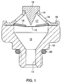
- the refrigerant relief device in Figs 1-4 includes a body 10 forming an axial refrigerant-introducing passage 11 (a hollow cylindrical portion of the body 10) and an axial refrigerant-introducing chamber 12.
- the refrigerant-introducing passage 11 forms a joint for connection to piping of a refrigeration cycle.
- a part of the outer periphery of the hollow cylindrical portion has an external thread.
- a metallic thin film 13 is disposed on an upper surface of the body 10.
- the thin film is brought into intimate contact with the upper surface such that the metal thin film 13 tightly closes the refrigerant-introducing chamber 12.
- the metal thin film 13 is welded to the upper surface of the body 10 outside the refrigerant-introducing chamber 12 e.g. to gastightly seal at the entire circumference of the upper opening.
- a housing 14 is disposed above the body 10 sandwiching the metal thin film 13.
- An outer periphery of the housing 14 is rigidly fixed to the body 10 by inwardly swaging a hollow cylindrical portion 15 of the body 10.
- the housing 14 has a plurality of openings 16 and defines an open-to-atmosphere chamber 17above the metal thin film 13.
- a piercing rod 18 is rigidly fixed serving to selectively break the metal thin film 13.
- the piercing rod 18 has a thin film-breaking section with a pointed tip opposed to the metal thin film 13.
- a Belleville spring 19 serving as a thin film-holder is disposed in the open-to-atmosphere chamber 17, for holding and supporting the metal thin film 13 so as to define a certain amount of axial displacement of the film 13 by the refrigerant pressure before the refrigerant pressure reaches a set pressure.
- the Belleville spring 19 is an annular disc spring having a frustoconical shape with a central hole. A central portion of the Belleville spring 19, i.e.
- the edge of the central hole slightly protrudes relative to the plane of the outer spring edge towards the refrigerant-introducing chamber 12.
- the outer spring periphery is retained by the housing 14.
- the Belleville spring 19 maintains its conical shape even when the metal thin film 13 intimately contacts the spring by the refrigerant pressure in the refrigerant-introducing passage 11 remaining below the set pressure.
- the axial positional conical relationship between the central portion of the spring receiving the metal thin film 13 and the outer periphery retained by the housing 14 is inverted such that the conical Bellville spring 19 snaps to the other side.
- An 0-ring 20 is fitted on a root portion of the hollow cylindrical portion so as to prevent refrigerant leakage when the refrigerant relief device is screwed to the piping of the refrigeration cycle.
- the Belleville spring 19 remains in the state shown in Fig. 1 and holds the metal thin film 13 against the acting pressure away from the tip of the piercing rod 18.
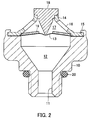
- the Belleville spring 19 is inverted in shape (Fig. 2). The central portion of the metal thin film 13 is displaced upward with the central portion of the spring to a location higher than the position of the tip of the piercing rod 18. Then, the metal thin film 13 is pierced and broken by the tip of the piercing rod 18.
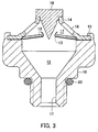
- the size of the hole broken into the metal thin film 13 then is increased by the flowing refrigerant.
- Refrigerant from the refrigeration cycle is released into the atmosphere through the then large hole and through the openings 16 of the housing 14.
- the refrigerant pressure in the refrigeration cycle suddenly decreases, preventing that components connected to in a highpressure line will break.
- the set pressure can be accurately measured by attaching the refrigerant relief device without the piercing rod 18 to a pressure-measuring jig, and increasing the pressure in the refrigerant-introducing chamber 12 until the Belleville spring 19 inverts the shape. Then the respective pressure is read. The Belleville spring 19 then can be restored to its original state without damaging the metal thin film 13 by applying an external force to the spring through the hole into which the piercing rod 18 will be mounted later. After the accurate determination of the set pressure, the piercing rod 18 is mounted in the housing 14.
- the piercing rod tip opposed to the metal thin film 13 is pointed so as to easily break the metal thin film 13 when the film 13 has been displaced far enough.
- the rod tip can have a conical shape, as shown in Figs. 5A and 5B.
- the contour of the tip can be a quadrangular pyramid (Fig. 5C), a star shape (Fig. 5D), and a spear tip-like shape (Fig. 5E).
- Figs. 5B and 5E a quadrangular pyramid
- Fig. 5D a star shape
- Fig. 5E spear tip-like shape
- the tip of the piercing rod 18 has portions (Figs. 5B and 5E) formed such that they have an acute angle in circumferential direction, the piercing rod 18 can easily pierce a hole through the thin metal film.
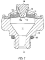
- the refrigerant relief device of Figs 6-9 (second embodiment) is distinguished from the first embodiment in that the thin film-holder is formed by three e.g. equally dimensioned Belleville springs 19a, 19b, and 19c overlaid upon each other in a stack.
- a plurality of types of refrigerant relief devices operating at different set pressures can be made by accordingly combining Belleville springs 19a, 19b, and 19c which need different loads for inverting the shape.
- Three Belleville springs 19a, 19b, and 19c are not limitative, but a combination of two or more than three disc Belleville springs as well is possible.
- the actual set pressure can be accurately measured in advance by a test as mentioned above.
- the Belleville springs 19a, 19b, and 19c are in a state shown in Fig. 6.
- the Belleville springs 19a, 19b, and 19c are inverted in shape (Fig. 7), and the thin film 13 is pierced and broken.
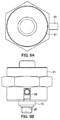
- the refrigerant relief device of Figs 9A, 9B, 10-12 (third embodiment) is distinguished from the first and second embodiments in that the structure of the thin film-breaking section is modified.
- the thin film-breaking section is automatically operated by the refrigerant pressure. Even when the refrigerant pressure is not higher than the set pressure but at the set pressure, the thin film-breaking positively is operated at a desired time point to then release the refrigerant into the atmosphere.
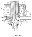
- the refrigerant relief device comprises the body 10 forming a joint for connection to piping of the refrigeration cycle.
- a solenoid 21 is disposed above the body 10 and forms part of the thin film-breaking section.
- the solenoid 21 is provided with a conduit 22 configured to extend from a side thereof, for releasing refrigerant into the atmosphere.
- the outer periphery of solenoid 21 has the shape of nut, to facilitate joining the refrigerant relief device to the piping of the refrigeration cycle by screwing.
- the piercing rod 18 is movable forward and backward in directions perpendicular to the plane of the metal thin film 13.
- the piercing rod 18 is rigidly fixed to a movable core 23 of the solenoid 21.
- the movable core 23 has an axial hole, and is urged by a spring 24 in a direction away from a fixed core 25.
- the fixed core 25 is disposed on the upper surface of the body 10 where the metal thin film 13 is welded.
- the piercing rod 18 and the spring 24 are received in a hole of the fixed core 25.
- the fixed core 25 has a lower end integrally formed with a flange portion protruding radially outward for forming a magnetic circuit.
- a horizontal hole communicates the open-to-atmosphere chamber 17 with the atmosphere.
- the Belleville spring 19 is disposed between the fixed core 25 and the metal thin film 13 for holding the metal thin film 13.
- a coil 26 is disposed around the outer peripheries of the movable core 23 and the fixed core 25.
- a bobbin for the coil 26 has a container containing the movable core 23 and the fixed core 25, and the conduit 22 for releasing refrigerant into the atmosphere.
- the container and the conduit 22 being integrally formed with the bobbin e.g. by a resin.
- the refrigerant relief device is disposed e.g. in refrigerant piping in an engine room. If the location where the refrigerant relief device is disposed is not suitable for releasing refrigerant, a hose may be connected to the conduit 22, to thereby guide refrigerant to a suitable location.
- a yoke 27 closing the magnetic circuit is disposed outside the coil 26, a yoke 27 closing the magnetic circuit is disposed. A lower end of the yoke 27 is rigidly fixed to the body 10 by inwardly swaging.
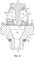
- the Belleville spring 19 has the state shown in Fig. 10.
- the metal thin film 13 is held against the refrigerant pressure away from the tip of the piercing rod 18.
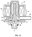
- the Belleville spring 19 When the refrigerant pressure has reached or has become higher than the set pressure, the Belleville spring 19 is inverted in shape (Fig 11). The central portion of the metal thin film 13 is displaced upward to a location higher than the position of the tip of the piercing rod 18. Thereby, the metal thin film 13 is pierced and broken. The size of the hole formed in the film 13 is instantly increased by flowing refrigerant (Fig. 12), and refrigerant is released into the atmosphere via the hole increased in size, the open-to-atmosphere chamber 17, and the conduit 22.
- the movable core 23 When the pulse current ceases, the movable core 23 is moved away from the fixed core 25 by the urging force of the spring 24.
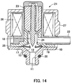
- the piercing rod 18 is pushed back by refrigerant blowing through the broken metal thin film 13. After that, as shown in FIG. 14, the metal thin film 13 is further ruptured by the force of the refrigerant blow to increase the size of the hole. Refrigerant is instantly released into the atmosphere via the conduit 22. This prevents that a dangerously large amount of refrigerant will enter the vehicle compartment, and prevents occupants from being exposed to peril by emitted refrigerant.
- the refrigerant relief device in Fig. 15 is distinguished from the third embodiment in that the thin film-holder is formed by a stack of e.g. three e.g. equally dimensioned Belleville springs 19a, 19b, and 19c which are overlaid upon each other. This allows to combine Belleville springs 19a, 19b, and 19c which have different loads for inverting the shape. It is possible to make a plurality of types of refrigerant relief devices operating at different set pressures.
- the refrigerant relief device of Fig. 16 (fifth embodiment) is distinguished from the first embodiment by a differently configured thin film-holder.
- the open-to-atmosphere chamber 17 in Fig. 16 contains a flat disc 28, which cannot be deformed axially, and which is in contact with the metal thin film 13.
- a spring 29 is disposed between the disc 28 and a root portion of the piercing rod 18.
- the thin film-holder is formed by the disc 28 and the spring 29.
- the disc 28 has an outer diameter large enough to be placed on an upper surface of the body 10, with the metal thin film 13, in-between.
- the disc 28 can axially move along the inner wall of the housing 14 when the metal thin film 13 is displaced axially.
- the spring 29 has a spring force large enough to withstand normal refrigerant pressure.
- the disc 28 has a central through hole in which the pointed tip of the piercing rod 18 is located.
- the axial position of the piercing rod 18 is adjusted such that the tip is located at a position to which the metal thin film 13 will become displaced e.g. when the refrigerant pressure becomes equal to the set pressure at which the refrigerant relief device should operate.
- the metal thin film 13 is displaced upward against the urging force of the spring 29.
- the refrigerant pressure reaches or exceeds the set pressure which should be detected as an abnormally high pressure
- the metal thin film 13 is brought into contact with the tip of the piercing rod 18.
- the thin film 13 will be damaged by the piercing rod 18.
- refrigerant flows through the broken portion into the atmosphere via the open-to-atmosphere chamber 17 and the openings 16.
Landscapes
- Engineering & Computer Science (AREA)
- General Engineering & Computer Science (AREA)
- Mechanical Engineering (AREA)
- Physics & Mathematics (AREA)
- Thermal Sciences (AREA)
- Chemical & Material Sciences (AREA)
- Chemical Kinetics & Catalysis (AREA)
- Air-Conditioning For Vehicles (AREA)
- Safety Valves (AREA)
Applications Claiming Priority (1)
| Application Number | Priority Date | Filing Date | Title |
|---|---|---|---|
| JP2004216757A JP2006038309A (ja) | 2004-07-26 | 2004-07-26 | 冷媒リリーフ装置 |
Publications (3)
| Publication Number | Publication Date |
|---|---|
| EP1621376A2 true EP1621376A2 (fr) | 2006-02-01 |
| EP1621376A3 EP1621376A3 (fr) | 2006-10-18 |
| EP1621376B1 EP1621376B1 (fr) | 2008-05-28 |
Family
ID=35207362
Family Applications (1)
| Application Number | Title | Priority Date | Filing Date |
|---|---|---|---|
| EP20050015090 Expired - Fee Related EP1621376B1 (fr) | 2004-07-26 | 2005-07-12 | Dispositif de décharge de frigorigène |
Country Status (5)
| Country | Link |
|---|---|
| US (1) | US20060016475A1 (fr) |
| EP (1) | EP1621376B1 (fr) |
| JP (1) | JP2006038309A (fr) |
| KR (1) | KR20060046725A (fr) |
| DE (1) | DE602005007112D1 (fr) |
Cited By (1)
| Publication number | Priority date | Publication date | Assignee | Title |
|---|---|---|---|---|
| DE102006004781A1 (de) * | 2006-02-02 | 2007-08-09 | Thomas Magnete Gmbh | Expansionsventil für eine Klimaanlage |
Families Citing this family (13)
| Publication number | Priority date | Publication date | Assignee | Title |
|---|---|---|---|---|
| WO2008054383A1 (fr) * | 2006-10-31 | 2008-05-08 | Carrier Corporation | Détection de libération de fluide frigorigène dans des systèmes frigorifiques utilisant du co2 |
| US20100269523A1 (en) * | 2008-01-17 | 2010-10-28 | Carrier Corporation | Mounting of pressure relief devices in a high pressure refrigeration system |
| US8671967B2 (en) * | 2009-08-07 | 2014-03-18 | Autoliv Asp, Inc. | Relief valve |
| SG178553A1 (en) * | 2009-08-25 | 2012-03-29 | Carrier Corp | Method and apparatus to indicate activation of pressure relief device |
| US8714175B2 (en) * | 2010-02-24 | 2014-05-06 | Applied Separations, Inc. | Pressure relief system for pressure vessels |
| FR2978536B1 (fr) * | 2011-07-25 | 2013-08-23 | Valeo Systemes Thermiques | Bouteille reservoir de fluide refrigerant et echangeur de chaleur comprenant une telle bouteille |
| US9289856B2 (en) * | 2013-07-29 | 2016-03-22 | Fike Corporation | Creation of laser-defined structures on pressure relief devices via tiling method |
| WO2017126836A1 (fr) * | 2016-01-18 | 2017-07-27 | 한온시스템 주식회사 | Système de climatisation de véhicule |
| CN107848372B (zh) * | 2016-01-18 | 2020-08-07 | 翰昂汽车零部件有限公司 | 车辆用空调系统 |
| US10494164B2 (en) | 2016-03-09 | 2019-12-03 | Fifth Third Bank, an Ohio Banking | Dispensable containment vessel and dispensing system |
| JP7000837B2 (ja) | 2017-12-18 | 2022-01-19 | 株式会社デンソー | 車両用空調装置 |
| CN114148459B (zh) * | 2022-01-07 | 2023-02-17 | 江南造船(集团)有限责任公司 | 一种适用于低温液货舱的泄漏液货收集装置 |
| US20250129894A1 (en) * | 2023-10-18 | 2025-04-24 | Lockheed Martin Corporation | Pressure relief shipping adapter |
Citations (1)
| Publication number | Priority date | Publication date | Assignee | Title |
|---|---|---|---|---|
| JP2002257047A (ja) | 2001-03-02 | 2002-09-11 | Toyota Industries Corp | 圧縮機用リリーフバルブ |
Family Cites Families (13)
| Publication number | Priority date | Publication date | Assignee | Title |
|---|---|---|---|---|
| US1671368A (en) * | 1926-01-18 | 1928-05-29 | Co Fire Equipment Co | Electromagnetic control for fluid containers |
| US2019421A (en) * | 1934-09-13 | 1935-10-29 | Edgar T Link | Attachment for refrigerating systems |
| US3155271A (en) * | 1963-07-05 | 1964-11-03 | Calmec Mfg Corp | Rupture disc mounting |
| US4083187A (en) * | 1975-12-09 | 1978-04-11 | Tokico Ltd. | Actuator for emergency operation |
| US4064003A (en) * | 1976-03-29 | 1977-12-20 | The United States Of America As Represented By The United States Energy Research And Development Administration | Rupture disc |
| US4948931A (en) * | 1989-04-17 | 1990-08-14 | Therm-O-Disc, Incorporated | Combined pressure cutoff and pressure relief valve |
| US5010911A (en) * | 1989-12-15 | 1991-04-30 | Wormald U.S., Inc. | Electromagnetic valve operator |
| US5076312A (en) * | 1990-01-25 | 1991-12-31 | Tip Engineering Group, Inc. | Pressure relief device |
| US5153396A (en) * | 1991-03-18 | 1992-10-06 | General Motors Corporation | Combination high pressure switch and valve device |
| US5644930A (en) * | 1994-08-11 | 1997-07-08 | Albertson; Luther D. | Mechanical pressure relief valve having a variable position outlet |
| US7093451B2 (en) * | 2003-09-18 | 2006-08-22 | Delphi Technologies, Inc. | Blowoff valve assembly with integrated pressure switch |
| JP2005273930A (ja) * | 2004-03-23 | 2005-10-06 | Tgk Co Ltd | 冷媒リリーフ装置 |
| JP4243211B2 (ja) * | 2004-04-06 | 2009-03-25 | 株式会社テージーケー | 冷凍システム |
-
2004
- 2004-07-26 JP JP2004216757A patent/JP2006038309A/ja active Pending
-
2005
- 2005-07-12 EP EP20050015090 patent/EP1621376B1/fr not_active Expired - Fee Related
- 2005-07-12 DE DE200560007112 patent/DE602005007112D1/de not_active Expired - Lifetime
- 2005-07-22 US US11/186,809 patent/US20060016475A1/en not_active Abandoned
- 2005-07-25 KR KR1020050067105A patent/KR20060046725A/ko not_active Withdrawn
Patent Citations (1)
| Publication number | Priority date | Publication date | Assignee | Title |
|---|---|---|---|---|
| JP2002257047A (ja) | 2001-03-02 | 2002-09-11 | Toyota Industries Corp | 圧縮機用リリーフバルブ |
Non-Patent Citations (1)
| Title |
|---|
| MAHMOUD GHODBANE ET AL.: "R- 152a Mobile A/C with Directed Relief Safety System", SAE 2003 ALTERNATE REFRIGERANTS SYSTEMS SYMPOSIUM, 8 January 2003 (2003-01-08), pages 4, Retrieved from the Internet <URL:URL:http://www.sae.org/altrefrigerant/presentations/presw-hill.pdf> |
Cited By (2)
| Publication number | Priority date | Publication date | Assignee | Title |
|---|---|---|---|---|
| DE102006004781A1 (de) * | 2006-02-02 | 2007-08-09 | Thomas Magnete Gmbh | Expansionsventil für eine Klimaanlage |
| DE102006004781B4 (de) * | 2006-02-02 | 2007-11-15 | Thomas Magnete Gmbh | Expansionsventil für eine Klimaanlage |
Also Published As
| Publication number | Publication date |
|---|---|
| JP2006038309A (ja) | 2006-02-09 |
| DE602005007112D1 (de) | 2008-07-10 |
| EP1621376B1 (fr) | 2008-05-28 |
| US20060016475A1 (en) | 2006-01-26 |
| KR20060046725A (ko) | 2006-05-17 |
| EP1621376A3 (fr) | 2006-10-18 |
Similar Documents
| Publication | Publication Date | Title |
|---|---|---|
| EP1621376B1 (fr) | Dispositif de décharge de frigorigène | |
| JP4243211B2 (ja) | 冷凍システム | |
| US7386987B2 (en) | Refrigerant relief device | |
| JP4255807B2 (ja) | 電磁リリーフ弁付膨張弁 | |
| US9746092B2 (en) | Valve assembly, in particular for space travel drive systems, which is closed when not actuated | |
| JP4511937B2 (ja) | コンプレッサー | |
| US6431196B1 (en) | Combination pressure relief device | |
| EP2020548A1 (fr) | Soupape de décharge de sécurité | |
| US7093451B2 (en) | Blowoff valve assembly with integrated pressure switch | |
| US9901762B2 (en) | Method and mechanism for fast evacuation of a pressurized vessel | |
| US20090235673A1 (en) | Detection of refrigerant release in co2 refrigerant systems | |
| US7322210B2 (en) | Receiver drier with relief valve | |
| US5577389A (en) | Rupture disk fragment collection trap for refrigeration systems | |
| JP3355548B2 (ja) | 車両用冷凍装置 | |
| KR20170114899A (ko) | 자동차의 안전 장치 | |
| JP2006199183A (ja) | 膨張装置 | |
| WO1997048954A1 (fr) | Systeme de securite pour unites d'air conditionne et de refrigeration | |
| EP4349422B1 (fr) | Système d'extinction d'incendie comprenant un dispositif d'indication de tension de cable | |
| JP7664742B2 (ja) | 空気調和機および圧力解放弁 | |
| JPH04225768A (ja) | 溶栓付圧力スイッチ | |
| HK1135170B (en) | Detection of refrigerant release in co2 refrigerant systems | |
| HK1170792A (en) | Method and apparatus to indicate activation of pressure relief device | |
| JPS6115347B2 (fr) | ||
| JPH07220939A (ja) | 油入電機の放圧装置 | |
| JP2005238871A (ja) | フェール制御装置 |
Legal Events
| Date | Code | Title | Description |
|---|---|---|---|
| PUAI | Public reference made under article 153(3) epc to a published international application that has entered the european phase |
Free format text: ORIGINAL CODE: 0009012 |
|
| AK | Designated contracting states |
Kind code of ref document: A2 Designated state(s): AT BE BG CH CY CZ DE DK EE ES FI FR GB GR HU IE IS IT LI LT LU LV MC NL PL PT RO SE SI SK TR |
|
| AX | Request for extension of the european patent |
Extension state: AL BA HR MK YU |
|
| PUAL | Search report despatched |
Free format text: ORIGINAL CODE: 0009013 |
|
| AK | Designated contracting states |
Kind code of ref document: A3 Designated state(s): AT BE BG CH CY CZ DE DK EE ES FI FR GB GR HU IE IS IT LI LT LU LV MC NL PL PT RO SE SI SK TR |
|
| AX | Request for extension of the european patent |
Extension state: AL BA HR MK YU |
|
| 17P | Request for examination filed |
Effective date: 20070227 |
|
| AKX | Designation fees paid |
Designated state(s): DE FR |
|
| GRAP | Despatch of communication of intention to grant a patent |
Free format text: ORIGINAL CODE: EPIDOSNIGR1 |
|
| GRAS | Grant fee paid |
Free format text: ORIGINAL CODE: EPIDOSNIGR3 |
|
| GRAA | (expected) grant |
Free format text: ORIGINAL CODE: 0009210 |
|
| AK | Designated contracting states |
Kind code of ref document: B1 Designated state(s): DE FR |
|
| REF | Corresponds to: |
Ref document number: 602005007112 Country of ref document: DE Date of ref document: 20080710 Kind code of ref document: P |
|
| PLBE | No opposition filed within time limit |
Free format text: ORIGINAL CODE: 0009261 |
|
| STAA | Information on the status of an ep patent application or granted ep patent |
Free format text: STATUS: NO OPPOSITION FILED WITHIN TIME LIMIT |
|
| 26N | No opposition filed |
Effective date: 20090303 |
|
| PGFP | Annual fee paid to national office [announced via postgrant information from national office to epo] |
Ref country code: DE Payment date: 20130730 Year of fee payment: 9 |
|
| PGFP | Annual fee paid to national office [announced via postgrant information from national office to epo] |
Ref country code: FR Payment date: 20130719 Year of fee payment: 9 |
|
| REG | Reference to a national code |
Ref country code: DE Ref legal event code: R119 Ref document number: 602005007112 Country of ref document: DE |
|
| REG | Reference to a national code |
Ref country code: FR Ref legal event code: ST Effective date: 20150331 |
|
| PG25 | Lapsed in a contracting state [announced via postgrant information from national office to epo] |
Ref country code: DE Free format text: LAPSE BECAUSE OF NON-PAYMENT OF DUE FEES Effective date: 20150203 |
|
| REG | Reference to a national code |
Ref country code: DE Ref legal event code: R119 Ref document number: 602005007112 Country of ref document: DE Effective date: 20150203 |
|
| PG25 | Lapsed in a contracting state [announced via postgrant information from national office to epo] |
Ref country code: FR Free format text: LAPSE BECAUSE OF NON-PAYMENT OF DUE FEES Effective date: 20140731 |