EP1621443A2 - Zur Energieaufnahme benutzte Teleskopiereigenschaft - Google Patents
Zur Energieaufnahme benutzte Teleskopiereigenschaft Download PDFInfo
- Publication number
- EP1621443A2 EP1621443A2 EP05076554A EP05076554A EP1621443A2 EP 1621443 A2 EP1621443 A2 EP 1621443A2 EP 05076554 A EP05076554 A EP 05076554A EP 05076554 A EP05076554 A EP 05076554A EP 1621443 A2 EP1621443 A2 EP 1621443A2
- Authority
- EP
- European Patent Office
- Prior art keywords
- steering column
- connecting device
- locking member
- column assembly
- response
- Prior art date
- Legal status (The legal status is an assumption and is not a legal conclusion. Google has not performed a legal analysis and makes no representation as to the accuracy of the status listed.)
- Granted
Links
- 238000010521 absorption reaction Methods 0.000 title 1
- 239000006096 absorbing agent Substances 0.000 claims abstract description 45
- 239000002775 capsule Substances 0.000 claims description 9
- 238000000926 separation method Methods 0.000 description 2
- 208000027418 Wounds and injury Diseases 0.000 description 1
- 230000006378 damage Effects 0.000 description 1
- 230000003116 impacting effect Effects 0.000 description 1
- 208000014674 injury Diseases 0.000 description 1
- 239000000463 material Substances 0.000 description 1
- 239000002184 metal Substances 0.000 description 1
- 230000004048 modification Effects 0.000 description 1
- 238000012986 modification Methods 0.000 description 1
Images

Classifications
-
- B—PERFORMING OPERATIONS; TRANSPORTING
- B62—LAND VEHICLES FOR TRAVELLING OTHERWISE THAN ON RAILS
- B62D—MOTOR VEHICLES; TRAILERS
- B62D1/00—Steering controls, i.e. means for initiating a change of direction of the vehicle
- B62D1/02—Steering controls, i.e. means for initiating a change of direction of the vehicle vehicle-mounted
- B62D1/16—Steering columns
- B62D1/18—Steering columns yieldable or adjustable, e.g. tiltable
- B62D1/19—Steering columns yieldable or adjustable, e.g. tiltable incorporating energy-absorbing arrangements, e.g. by being yieldable or collapsible
- B62D1/195—Yieldable supports for the steering column
-
- B—PERFORMING OPERATIONS; TRANSPORTING
- B62—LAND VEHICLES FOR TRAVELLING OTHERWISE THAN ON RAILS
- B62D—MOTOR VEHICLES; TRAILERS
- B62D1/00—Steering controls, i.e. means for initiating a change of direction of the vehicle
- B62D1/02—Steering controls, i.e. means for initiating a change of direction of the vehicle vehicle-mounted
- B62D1/16—Steering columns
- B62D1/18—Steering columns yieldable or adjustable, e.g. tiltable
- B62D1/184—Mechanisms for locking columns at selected positions
Definitions
- the invention includes a steering column assembly positionable in a vehicle.
- the invention also includes a connecting device releasably attachable to the vehicle.
- the connecting device is moveable between a locked configuration and an unlocked configuration to selectively lock the steering column assembly with respect to the vehicle.
- the invention also includes a first energy absorber disposed between the connecting device and the steering column assembly.
- the first energy absorber is selectively engageable to dissipate energy.
- the first energy absorber is engaged to dissipate energy in response to relative movement between the connecting device and the steering column assembly when the connecting device is in the locked configuration.
- the first energy absorber is disengaged with respect to dissipating energy in response to relative movement between the connecting device and the steering column assembly when the connecting device is in the unlocked configuration.
- the invention allows the steering column to be fixed to the vehicle during normal vehicle handling while also allowing energy to be dissipated in an impact situation.
- the invention can be used in combination with one or more other energy absorbing devices to enhance the dissipation of energy.
- a second energy absorber can be disposed between the steering column and the vehicle to dissipate energy in response to relative movement between the steering column and the vehicle.
- a third energy absorber can be disposed between the connecting device and the vehicle to dissipate energy in response to relative movement between the connecting device and the vehicle.
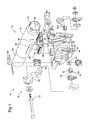
- an apparatus in a first exemplary embodiment of the invention, includes a steering column assembly 12 that is positionable in a vehicle.
- the apparatus also includes a connecting device 18 that is releasably attachable to the vehicle.
- the connecting device 18 is movable between a locked configuration and an unlocked configuration to selectively lock the steering column assembly 12 with respect to the vehicle.
- the apparatus also includes a first energy absorber 20 disposed between the connecting device 18 and the steering column assembly 12.
- the first energy absorber 20 is engaged to dissipate energy in response to relative movement between the connecting device 18 and the steering column assembly 12 when the connecting device 18 is in the locked configuration.
- the first energy absorber 20 is disengaged with respect to dissipating energy in response to relative movement between the connecting device 18 and the steering column 12 when the connecting device 18 is in the unlocked configuration.
- the connecting device 18 includes a first locking member 30 that is slidably associated with the steering column assembly 12.
- the first locking member 30 is disposed between first and second surfaces 34, 36 defined by the bracket 46 of the first steering column member 14.
- the connecting device 18 also includes a second locking member 32 that is movable between a locked position and an unlocked position.
- the exemplary embodiment of the invention includes a pair of second locking members 32, 32a disposed on opposite sides the first locking member 30. When in the locked position, the second locking member 32 contacts the first locking member 30 and the members 30, 32 are immovably associated with one another. When in the unlocked position, the second locking member 32 is spaced from the first locking member 30.
- a lever 70 engages the second locking member 32.
- a driver of the vehicle can rotate the lever 70 along an arcuate path of movement 72 to move the second locking member 32 from the locked position to the unlocked position.
- the driver can adjust the position of the steering wheel in the vehicle telescopically and tiltably.
- the lever 70 can be rotated back along the path of movement 72 to move the second locking member 32 to the locked position.
- the apparatus 10 includes a biasing device 60 that urges the second locking member 32 to the locked position.
- a separating force is generated when the driver of the vehicle impacts the steering column assembly 12 during a crash. If the generating force is not greater than the second predetermined level of force, the steering column assembly 12 will remain fixed with respect to the vehicle. If the separating force is greater than the second predetermined level of force, the third locking member 42 and the capsule 62 will separate and the connecting device 18 and steering column assembly 12 will concurrently move along a first translating collapse path.
- the connecting device 18 can engage another structure in the vehicle such as a crossbeam and cease to move. After the connecting device 18 ceases to move, the connecting device 18 and the steering column assembly 12 can separate from one another in response to a separating force greater than the first predetermined level of force.
- the steering assembly column 12 will move along a second translating collapse path after separation from the connecting device 18.
- the first locking member 30, the second locking member 32 and the third locking member 44 are fixed relative to one another and the first locking member 30 slides with respect to the bracket 46.
- the strap 24 is drawn over the anvil 22 to dissipate energy.
- the first and second translating collapse paths are disposed in series. As a result, the length over which a deformable member such as the straps 24, 68 can be drawn, is increased.
- the movement of the steering column assembly 12 along either of the first or second translating collapse paths can correspond to telescoping movement of the first and second steering column members 14, 16 relative to one another.
- the first steering column member 14 could be telescopically collapsing relative to the second steering column member 16 during movement of the steering column assembly 12 along one of or both of the first and second translating collapse paths.
- movement of the steering column assembly 12 along both of the first and second collapse paths can be translating movement in which the first and second steering column members 14, 16 are fixed relative to one another.
- the capsule 62 and the third locking member 42 separate in response to a separating force greater than the second predetermined level of force.
- the connecting device 18 and the first steering column member 14 separate in response to a separating force greater than the first predetermined level of force.
- the first predetermined level of force is greater than the second predetermined level of force.
- the capsule 62 and third locking member 42 separate before the connecting device 18 separates from the steering column assembly 12.
- the first predetermined level of force could be less than the second predetermined level of force.
- the capsule 62 and third locking member 42 separate after the connecting device 18 separates from the steering column assembly 12.
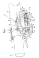
- an apparatus 110 in a second exemplary embodiment of the invention, includes a steering column assembly 112 having first and second steering column members 114, 116.
- a connecting device 118 releasably connects the steering column assembly 112 to the vehicle.
- a first energy absorber 120 is disposed between the connecting device 118 and the steering column assembly 112.
- the first energy absorber 120 includes the first anvil 122 and the first strap 124.
- the steering column assembly 112 includes a steering wheel supporting end 126 and a pivoting end 128.
- the connecting device 118 includes a first locking member 130, a second locking member 132, and a third locking member 142.
- the first locking member 130 is disposed between first and second surfaces 134, 136 of a bracket 146.
- the first locking member 130 defines a first locking portion 138.
- the third locking member 142 includes a third locking portion 144 defining a plurality of teeth 154.
- a bracket 146 associated with the first steering column member 114 defines a first slot 148 and the third locking member 142 defines a second slot 150.
- a biasing device 160 biases the second locking member 132 to the locked position.
- a third energy absorber 174 includes a capsule 162 disposed between the third locking member 142 and the vehicle.
- a second energy absorber 164 is disposed in parallel to the third energy absorber 174 and includes a second anvil 166 and a second strap 168.
Landscapes
- Engineering & Computer Science (AREA)
- Chemical & Material Sciences (AREA)
- Combustion & Propulsion (AREA)
- Transportation (AREA)
- Mechanical Engineering (AREA)
- Steering Controls (AREA)
- Lock And Its Accessories (AREA)
- Solid-Sorbent Or Filter-Aiding Compositions (AREA)
- Diaphragms For Electromechanical Transducers (AREA)
Applications Claiming Priority (1)
| Application Number | Priority Date | Filing Date | Title |
|---|---|---|---|
| US10/899,811 US7484430B2 (en) | 2004-07-27 | 2004-07-27 | Telescope feature used for energy absorption |
Publications (3)
| Publication Number | Publication Date |
|---|---|
| EP1621443A2 true EP1621443A2 (de) | 2006-02-01 |
| EP1621443A3 EP1621443A3 (de) | 2006-05-24 |
| EP1621443B1 EP1621443B1 (de) | 2008-02-06 |
Family
ID=35159673
Family Applications (1)
| Application Number | Title | Priority Date | Filing Date |
|---|---|---|---|
| EP05076554A Expired - Lifetime EP1621443B1 (de) | 2004-07-27 | 2005-07-07 | Zur Energieaufnahme benutzte Teleskopiereigenschaft |
Country Status (4)
| Country | Link |
|---|---|
| US (1) | US7484430B2 (de) |
| EP (1) | EP1621443B1 (de) |
| AT (1) | ATE385487T1 (de) |
| DE (1) | DE602005004632T2 (de) |
Cited By (1)
| Publication number | Priority date | Publication date | Assignee | Title |
|---|---|---|---|---|
| EP2296956B1 (de) * | 2008-06-04 | 2016-10-26 | Robert Bosch Automotive Steering Vendôme | Verbesserte einstellbare lenksäule für kraftfahrzeuge |
Families Citing this family (35)
| Publication number | Priority date | Publication date | Assignee | Title |
|---|---|---|---|---|
| US7942446B2 (en) * | 2004-04-30 | 2011-05-17 | Nexteer (Beijing) Technology Co., Ltd. | Horizontal hybrid collapsing steering column |
| US7421925B2 (en) * | 2004-12-16 | 2008-09-09 | William Korzan | Steering column tilt adjusting system |
| US8056437B2 (en) * | 2005-04-19 | 2011-11-15 | Nexteer (Beijing) Technology Co., Ltd. | Electric steering column lock with single direction actuator travel |
| US7861615B2 (en) * | 2005-04-19 | 2011-01-04 | Gm Global Technology Operations, Inc. | Adjustable steering column assembly |
| US20060230863A1 (en) * | 2005-04-19 | 2006-10-19 | Delphi Technologies, Inc. | Steering column with rake and telescope adjustment |
| DE102005052123B3 (de) * | 2005-10-28 | 2007-01-11 | Thyssenkrupp Presta Ag | Lenksäule für ein Kraftfahrzeug |
| US20070242160A1 (en) * | 2006-04-18 | 2007-10-18 | Marvell International Ltd. | Shared memory multi video channel display apparatus and methods |
| US20070295145A1 (en) * | 2006-05-30 | 2007-12-27 | Nsk Ltd. | Steering device |
| US7611165B2 (en) * | 2006-06-23 | 2009-11-03 | Delphi Technologies, Inc. | Adjustable steering column assembly having an attached instrument cluster |
| US7533594B2 (en) * | 2006-12-13 | 2009-05-19 | Delphi Technologies, Inc. | Position control apparatus for steering column |
| US7635149B2 (en) * | 2007-03-21 | 2009-12-22 | Gm Global Technology Operations, Inc. | Rocker-arm lock device of an adjustable steering column assembly |
| US8047096B2 (en) * | 2007-03-30 | 2011-11-01 | Nexteer (Beijing) Technology Co., Ltd. | Lock mechanism for an adjustable steering column assembly |
| US7685903B2 (en) * | 2008-05-19 | 2010-03-30 | Gm Global Technology Operations, Inc. | Dual on-center column lock mechanism |
| DE102008034807B3 (de) * | 2008-07-24 | 2009-10-01 | Thyssenkrupp Presta Ag | Lenksäule für ein Kraftfahrzeug |
| JP5412799B2 (ja) * | 2008-11-13 | 2014-02-12 | 株式会社ジェイテクト | ステアリング装置 |
| DE102010044495B4 (de) * | 2009-09-07 | 2014-07-03 | Mando Corporation | Lenksäule für ein Fahrzeug |
| DE102009059159B3 (de) | 2009-12-16 | 2011-01-27 | Thyssenkrupp Presta Ag | Lenksäule für ein Kraftfahrzeug |
| US8657338B2 (en) * | 2012-06-29 | 2014-02-25 | Steering Solutions Ip Holding Corporation | Position lock for steering column |
| US8888131B2 (en) * | 2012-06-29 | 2014-11-18 | Steering Solutions Ip Holding Corporation | Position lock for steering column |
| US20140109714A1 (en) * | 2012-10-19 | 2014-04-24 | Steering Solutions Ip Holding Corporation | Cross axis rake and telescope lock |
| US8764064B2 (en) * | 2012-11-30 | 2014-07-01 | Steering Solutions Ip Holding Corporation | Steering column assembly with improved energy absorption system |
| US9545943B2 (en) * | 2014-09-17 | 2017-01-17 | Jtekt Corporation | Steering device |
| DE102014016510B4 (de) * | 2014-11-10 | 2016-02-18 | Thyssenkrupp Ag | Lenksäule mit Längsanschlag mit einstellbarer Freigabefunktion für Crash |
| KR101603020B1 (ko) * | 2014-12-18 | 2016-03-21 | 주식회사 만도 | 자동차의 조향 컬럼 |
| DE102015204476B3 (de) * | 2015-03-12 | 2016-05-25 | Thyssenkrupp Ag | Lenksäule für ein Kraftfahrzeug |
| JP6508518B2 (ja) * | 2015-03-31 | 2019-05-08 | 株式会社ジェイテクト | ステアリング装置 |
| CN107848557B (zh) * | 2015-04-24 | 2020-03-13 | 罗伯特·博世汽车转向有限责任公司 | 可调节转向柱锁 |
| JP6142967B2 (ja) * | 2015-05-19 | 2017-06-07 | 日本精工株式会社 | テレスコピック式ステアリング装置 |
| GB201514096D0 (en) * | 2015-08-10 | 2015-09-23 | Trw Ltd | A Steering Column Assembly |
| JP6621359B2 (ja) * | 2016-03-31 | 2019-12-18 | 富士機工株式会社 | ステアリングコラム装置 |
| JP6659428B2 (ja) * | 2016-03-31 | 2020-03-04 | 富士機工株式会社 | ステアリングコラム装置 |
| EP3421326A4 (de) * | 2016-04-08 | 2019-04-24 | NSK Ltd. | Positionsanpassungsvorrichtung für ein lenkrad |
| DE102018201029B4 (de) * | 2017-01-26 | 2024-10-31 | Hl Mando Corporation | Neigungsvorrichtung für automobil-lenksäule |
| US10717457B2 (en) * | 2018-06-18 | 2020-07-21 | Steering Solutions Ip Holding Corporation | Steering column positive lock mechanism |
| JP7004417B2 (ja) * | 2018-08-31 | 2022-01-21 | 株式会社クボタ | 走行車両 |
Family Cites Families (9)
| Publication number | Priority date | Publication date | Assignee | Title |
|---|---|---|---|---|
| GB2291840A (en) | 1994-07-29 | 1996-02-07 | Torrington Co | Vehicle steering column reach adjustment and energy absorbing mechanism |
| US5820163A (en) * | 1996-07-08 | 1998-10-13 | Ford Global Technologies, Inc. | Tilting, telescoping and energy absorbing steering column |
| SE507771C2 (sv) | 1996-11-21 | 1998-07-13 | Volvo Ab | Anordning och förfarande för skydd av åkande i fordon |
| DE60006815T2 (de) | 1999-06-11 | 2004-05-27 | Delphi Technologies, Inc., Troy | Energieaufnehmer für kraftfahrzeuglenksäule |
| US6419269B1 (en) | 1999-09-20 | 2002-07-16 | Delphi Technologies | Locking system for adjustable position steering column |
| US6189929B1 (en) | 1999-11-02 | 2001-02-20 | Trw Inc. | Adaptive collapsible steering column |
| DE10039792A1 (de) * | 2000-08-16 | 2002-02-28 | Daimler Chrysler Ag | Lenksäule für ein Kraftfahrzeug |
| US6659504B2 (en) | 2001-05-18 | 2003-12-09 | Delphi Technologies, Inc. | Steering column for a vehicle |
| US6652002B2 (en) | 2001-10-19 | 2003-11-25 | Delphi Technologies, Inc. | Crash responsive energy absorbing device for a steering column |
-
2004
- 2004-07-27 US US10/899,811 patent/US7484430B2/en active Active
-
2005
- 2005-07-07 DE DE602005004632T patent/DE602005004632T2/de not_active Expired - Lifetime
- 2005-07-07 AT AT05076554T patent/ATE385487T1/de not_active IP Right Cessation
- 2005-07-07 EP EP05076554A patent/EP1621443B1/de not_active Expired - Lifetime
Non-Patent Citations (1)
| Title |
|---|
| None |
Cited By (1)
| Publication number | Priority date | Publication date | Assignee | Title |
|---|---|---|---|---|
| EP2296956B1 (de) * | 2008-06-04 | 2016-10-26 | Robert Bosch Automotive Steering Vendôme | Verbesserte einstellbare lenksäule für kraftfahrzeuge |
Also Published As
| Publication number | Publication date |
|---|---|
| EP1621443A3 (de) | 2006-05-24 |
| EP1621443B1 (de) | 2008-02-06 |
| US20060021460A1 (en) | 2006-02-02 |
| DE602005004632D1 (de) | 2008-03-20 |
| DE602005004632T2 (de) | 2009-01-29 |
| US7484430B2 (en) | 2009-02-03 |
| ATE385487T1 (de) | 2008-02-15 |
Similar Documents
| Publication | Publication Date | Title |
|---|---|---|
| EP1621443B1 (de) | Zur Energieaufnahme benutzte Teleskopiereigenschaft | |
| US7325834B2 (en) | Adaptive strap energy absorber with pin puller | |
| US8413541B2 (en) | Clamp assembly for a steering column assembly | |
| EP0598857B1 (de) | Vorrichtung zur absorbierung von,von der fahrzeuglenksäule übermittelter energie | |
| US5562307A (en) | Vehicle steering column adjustment and energy absorbing mechanism | |
| US7735868B2 (en) | Adjustable steering column assembly for a vehicle | |
| US8979128B2 (en) | Collapsible steering column assembly | |
| US7827880B2 (en) | Steering column assembly with a quick release bolt | |
| US8065931B1 (en) | Adjustable steering column assembly for a motor vehicle | |
| US8783717B2 (en) | Steering column telescope lock | |
| CN109789890B (zh) | 溃缩转向柱组件 | |
| US20150096404A1 (en) | Collapsible steering column assembly | |
| EP1728702A1 (de) | Adaptiver Energieabsorber für eine Lenksäule | |
| EP1093990A2 (de) | Fahrzeuglenksäule | |
| CN111712424B (zh) | 带调节限位止动件的驾驶杆 | |
| CN109923023B (zh) | 转向柱组件 | |
| EP1728703B1 (de) | Adaptiv Energie aufnehmende Lenksäule | |
| US7503234B2 (en) | One lever tilt and telescope mechanism | |
| US10807632B2 (en) | Low initial resistance steering column crash apparatus | |
| US7229096B2 (en) | Adaptive energy absorbing system using pin pullers | |
| JP2004001758A (ja) | 車両用ステアリングコラム | |
| US20130305870A1 (en) | System and method for constraining a portion of a steering column assembly to translate along a preferred path |
Legal Events
| Date | Code | Title | Description |
|---|---|---|---|
| PUAI | Public reference made under article 153(3) epc to a published international application that has entered the european phase |
Free format text: ORIGINAL CODE: 0009012 |
|
| AK | Designated contracting states |
Kind code of ref document: A2 Designated state(s): AT BE BG CH CY CZ DE DK EE ES FI FR GB GR HU IE IS IT LI LT LU LV MC NL PL PT RO SE SI SK TR |
|
| AX | Request for extension of the european patent |
Extension state: AL BA HR MK YU |
|
| PUAL | Search report despatched |
Free format text: ORIGINAL CODE: 0009013 |
|
| AK | Designated contracting states |
Kind code of ref document: A3 Designated state(s): AT BE BG CH CY CZ DE DK EE ES FI FR GB GR HU IE IS IT LI LT LU LV MC NL PL PT RO SE SI SK TR |
|
| AX | Request for extension of the european patent |
Extension state: AL BA HR MK YU |
|
| 17P | Request for examination filed |
Effective date: 20061124 |
|
| AKX | Designation fees paid |
Designated state(s): AT BE BG CH CY CZ DE DK EE ES FI FR GB GR HU IE IS IT LI LT LU LV MC NL PL PT RO SE SI SK TR |
|
| 17Q | First examination report despatched |
Effective date: 20070104 |
|
| GRAP | Despatch of communication of intention to grant a patent |
Free format text: ORIGINAL CODE: EPIDOSNIGR1 |
|
| GRAS | Grant fee paid |
Free format text: ORIGINAL CODE: EPIDOSNIGR3 |
|
| GRAA | (expected) grant |
Free format text: ORIGINAL CODE: 0009210 |
|
| AK | Designated contracting states |
Kind code of ref document: B1 Designated state(s): AT BE BG CH CY CZ DE DK EE ES FI FR GB GR HU IE IS IT LI LT LU LV MC NL PL PT RO SE SI SK TR |
|
| REG | Reference to a national code |
Ref country code: GB Ref legal event code: FG4D |
|
| REG | Reference to a national code |
Ref country code: CH Ref legal event code: EP |
|
| REG | Reference to a national code |
Ref country code: IE Ref legal event code: FG4D |
|
| REF | Corresponds to: |
Ref document number: 602005004632 Country of ref document: DE Date of ref document: 20080320 Kind code of ref document: P |
|
| PG25 | Lapsed in a contracting state [announced via postgrant information from national office to epo] |
Ref country code: IS Free format text: LAPSE BECAUSE OF FAILURE TO SUBMIT A TRANSLATION OF THE DESCRIPTION OR TO PAY THE FEE WITHIN THE PRESCRIBED TIME-LIMIT Effective date: 20080606 Ref country code: ES Free format text: LAPSE BECAUSE OF FAILURE TO SUBMIT A TRANSLATION OF THE DESCRIPTION OR TO PAY THE FEE WITHIN THE PRESCRIBED TIME-LIMIT Effective date: 20080517 Ref country code: FI Free format text: LAPSE BECAUSE OF FAILURE TO SUBMIT A TRANSLATION OF THE DESCRIPTION OR TO PAY THE FEE WITHIN THE PRESCRIBED TIME-LIMIT Effective date: 20080206 |
|
| NLV1 | Nl: lapsed or annulled due to failure to fulfill the requirements of art. 29p and 29m of the patents act | ||
| PG25 | Lapsed in a contracting state [announced via postgrant information from national office to epo] |
Ref country code: AT Free format text: LAPSE BECAUSE OF FAILURE TO SUBMIT A TRANSLATION OF THE DESCRIPTION OR TO PAY THE FEE WITHIN THE PRESCRIBED TIME-LIMIT Effective date: 20080206 |
|
| ET | Fr: translation filed | ||
| PG25 | Lapsed in a contracting state [announced via postgrant information from national office to epo] |
Ref country code: PL Free format text: LAPSE BECAUSE OF FAILURE TO SUBMIT A TRANSLATION OF THE DESCRIPTION OR TO PAY THE FEE WITHIN THE PRESCRIBED TIME-LIMIT Effective date: 20080206 Ref country code: SI Free format text: LAPSE BECAUSE OF FAILURE TO SUBMIT A TRANSLATION OF THE DESCRIPTION OR TO PAY THE FEE WITHIN THE PRESCRIBED TIME-LIMIT Effective date: 20080206 Ref country code: LV Free format text: LAPSE BECAUSE OF FAILURE TO SUBMIT A TRANSLATION OF THE DESCRIPTION OR TO PAY THE FEE WITHIN THE PRESCRIBED TIME-LIMIT Effective date: 20080206 Ref country code: BE Free format text: LAPSE BECAUSE OF FAILURE TO SUBMIT A TRANSLATION OF THE DESCRIPTION OR TO PAY THE FEE WITHIN THE PRESCRIBED TIME-LIMIT Effective date: 20080206 |
|
| PG25 | Lapsed in a contracting state [announced via postgrant information from national office to epo] |
Ref country code: PT Free format text: LAPSE BECAUSE OF FAILURE TO SUBMIT A TRANSLATION OF THE DESCRIPTION OR TO PAY THE FEE WITHIN THE PRESCRIBED TIME-LIMIT Effective date: 20080707 Ref country code: CZ Free format text: LAPSE BECAUSE OF FAILURE TO SUBMIT A TRANSLATION OF THE DESCRIPTION OR TO PAY THE FEE WITHIN THE PRESCRIBED TIME-LIMIT Effective date: 20080206 Ref country code: SK Free format text: LAPSE BECAUSE OF FAILURE TO SUBMIT A TRANSLATION OF THE DESCRIPTION OR TO PAY THE FEE WITHIN THE PRESCRIBED TIME-LIMIT Effective date: 20080206 Ref country code: DK Free format text: LAPSE BECAUSE OF FAILURE TO SUBMIT A TRANSLATION OF THE DESCRIPTION OR TO PAY THE FEE WITHIN THE PRESCRIBED TIME-LIMIT Effective date: 20080206 Ref country code: NL Free format text: LAPSE BECAUSE OF FAILURE TO SUBMIT A TRANSLATION OF THE DESCRIPTION OR TO PAY THE FEE WITHIN THE PRESCRIBED TIME-LIMIT Effective date: 20080206 Ref country code: SE Free format text: LAPSE BECAUSE OF FAILURE TO SUBMIT A TRANSLATION OF THE DESCRIPTION OR TO PAY THE FEE WITHIN THE PRESCRIBED TIME-LIMIT Effective date: 20080506 |
|
| PG25 | Lapsed in a contracting state [announced via postgrant information from national office to epo] |
Ref country code: RO Free format text: LAPSE BECAUSE OF FAILURE TO SUBMIT A TRANSLATION OF THE DESCRIPTION OR TO PAY THE FEE WITHIN THE PRESCRIBED TIME-LIMIT Effective date: 20080206 |
|
| PLBE | No opposition filed within time limit |
Free format text: ORIGINAL CODE: 0009261 |
|
| STAA | Information on the status of an ep patent application or granted ep patent |
Free format text: STATUS: NO OPPOSITION FILED WITHIN TIME LIMIT |
|
| 26N | No opposition filed |
Effective date: 20081107 |
|
| PG25 | Lapsed in a contracting state [announced via postgrant information from national office to epo] |
Ref country code: LT Free format text: LAPSE BECAUSE OF FAILURE TO SUBMIT A TRANSLATION OF THE DESCRIPTION OR TO PAY THE FEE WITHIN THE PRESCRIBED TIME-LIMIT Effective date: 20080206 |
|
| PG25 | Lapsed in a contracting state [announced via postgrant information from national office to epo] |
Ref country code: MC Free format text: LAPSE BECAUSE OF NON-PAYMENT OF DUE FEES Effective date: 20080731 |
|
| PG25 | Lapsed in a contracting state [announced via postgrant information from national office to epo] |
Ref country code: EE Free format text: LAPSE BECAUSE OF FAILURE TO SUBMIT A TRANSLATION OF THE DESCRIPTION OR TO PAY THE FEE WITHIN THE PRESCRIBED TIME-LIMIT Effective date: 20080206 Ref country code: BG Free format text: LAPSE BECAUSE OF FAILURE TO SUBMIT A TRANSLATION OF THE DESCRIPTION OR TO PAY THE FEE WITHIN THE PRESCRIBED TIME-LIMIT Effective date: 20080506 |
|
| PG25 | Lapsed in a contracting state [announced via postgrant information from national office to epo] |
Ref country code: IE Free format text: LAPSE BECAUSE OF NON-PAYMENT OF DUE FEES Effective date: 20080707 Ref country code: CY Free format text: LAPSE BECAUSE OF FAILURE TO SUBMIT A TRANSLATION OF THE DESCRIPTION OR TO PAY THE FEE WITHIN THE PRESCRIBED TIME-LIMIT Effective date: 20080206 |
|
| PG25 | Lapsed in a contracting state [announced via postgrant information from national office to epo] |
Ref country code: IT Free format text: LAPSE BECAUSE OF FAILURE TO SUBMIT A TRANSLATION OF THE DESCRIPTION OR TO PAY THE FEE WITHIN THE PRESCRIBED TIME-LIMIT Effective date: 20080206 |
|
| REG | Reference to a national code |
Ref country code: CH Ref legal event code: PL |
|
| PG25 | Lapsed in a contracting state [announced via postgrant information from national office to epo] |
Ref country code: CH Free format text: LAPSE BECAUSE OF NON-PAYMENT OF DUE FEES Effective date: 20090731 Ref country code: LI Free format text: LAPSE BECAUSE OF NON-PAYMENT OF DUE FEES Effective date: 20090731 |
|
| PG25 | Lapsed in a contracting state [announced via postgrant information from national office to epo] |
Ref country code: LU Free format text: LAPSE BECAUSE OF NON-PAYMENT OF DUE FEES Effective date: 20080707 Ref country code: HU Free format text: LAPSE BECAUSE OF FAILURE TO SUBMIT A TRANSLATION OF THE DESCRIPTION OR TO PAY THE FEE WITHIN THE PRESCRIBED TIME-LIMIT Effective date: 20080807 |
|
| REG | Reference to a national code |
Ref country code: FR Ref legal event code: TP |
|
| PG25 | Lapsed in a contracting state [announced via postgrant information from national office to epo] |
Ref country code: TR Free format text: LAPSE BECAUSE OF FAILURE TO SUBMIT A TRANSLATION OF THE DESCRIPTION OR TO PAY THE FEE WITHIN THE PRESCRIBED TIME-LIMIT Effective date: 20080206 |
|
| PG25 | Lapsed in a contracting state [announced via postgrant information from national office to epo] |
Ref country code: GR Free format text: LAPSE BECAUSE OF FAILURE TO SUBMIT A TRANSLATION OF THE DESCRIPTION OR TO PAY THE FEE WITHIN THE PRESCRIBED TIME-LIMIT Effective date: 20080507 |
|
| REG | Reference to a national code |
Ref country code: GB Ref legal event code: 732E Free format text: REGISTERED BETWEEN 20101028 AND 20101103 |
|
| REG | Reference to a national code |
Ref country code: DE Ref legal event code: R081 Ref document number: 602005004632 Country of ref document: DE Owner name: GM GLOBAL TECHNOLOGY OPERATIONS LLC (N. D. GES, US Free format text: FORMER OWNER: DELPHI TECHNOLOGIES, INC., TROY, US Effective date: 20110412 Ref country code: DE Ref legal event code: R081 Ref document number: 602005004632 Country of ref document: DE Owner name: STEERING SOLUTIONS IP HOLDING CORP., US Free format text: FORMER OWNER: DELPHI TECHNOLOGIES, INC., TROY, US Effective date: 20110412 Ref country code: DE Ref legal event code: R081 Ref document number: 602005004632 Country of ref document: DE Owner name: STEERING SOLUTIONS IP HOLDING CORP., SAGINAW, US Free format text: FORMER OWNER: DELPHI TECHNOLOGIES, INC., TROY, MICH., US Effective date: 20110412 Ref country code: DE Ref legal event code: R081 Ref document number: 602005004632 Country of ref document: DE Owner name: GM GLOBAL TECHNOLOGY OPERATIONS LLC (N. D. GES, US Free format text: FORMER OWNER: DELPHI TECHNOLOGIES, INC., TROY, MICH., US Effective date: 20110412 |
|
| REG | Reference to a national code |
Ref country code: DE Ref legal event code: R082 Ref document number: 602005004632 Country of ref document: DE Representative=s name: MANITZ, FINSTERWALD & PARTNER GBR, DE |
|
| PGFP | Annual fee paid to national office [announced via postgrant information from national office to epo] |
Ref country code: GB Payment date: 20120725 Year of fee payment: 8 |
|
| REG | Reference to a national code |
Ref country code: DE Ref legal event code: R081 Ref document number: 602005004632 Country of ref document: DE Owner name: STEERING SOLUTIONS IP HOLDING CORP., US Free format text: FORMER OWNER: GM GLOBAL TECHNOLOGY OPERATIONS, INC., DETROIT, US Effective date: 20121019 Ref country code: DE Ref legal event code: R081 Ref document number: 602005004632 Country of ref document: DE Owner name: GM GLOBAL TECHNOLOGY OPERATIONS LLC (N. D. GES, US Free format text: FORMER OWNER: GM GLOBAL TECHNOLOGY OPERATIONS, INC., DETROIT, US Effective date: 20121019 Ref country code: DE Ref legal event code: R082 Ref document number: 602005004632 Country of ref document: DE Representative=s name: MANITZ, FINSTERWALD & PARTNER GBR, DE Effective date: 20121019 Ref country code: DE Ref legal event code: R081 Ref document number: 602005004632 Country of ref document: DE Owner name: GM GLOBAL TECHNOLOGY OPERATIONS LLC (N. D. GES, US Free format text: FORMER OWNER: GM GLOBAL TECHNOLOGY OPERATIONS, INC., DETROIT, MICH., US Effective date: 20121019 Ref country code: DE Ref legal event code: R081 Ref document number: 602005004632 Country of ref document: DE Owner name: STEERING SOLUTIONS IP HOLDING CORP., SAGINAW, US Free format text: FORMER OWNER: GM GLOBAL TECHNOLOGY OPERATIONS, INC., DETROIT, MICH., US Effective date: 20121019 |
|
| PGFP | Annual fee paid to national office [announced via postgrant information from national office to epo] |
Ref country code: FR Payment date: 20120731 Year of fee payment: 8 Ref country code: DE Payment date: 20120727 Year of fee payment: 8 |
|
| REG | Reference to a national code |
Ref country code: DE Ref legal event code: R082 Ref document number: 602005004632 Country of ref document: DE Representative=s name: MANITZ, FINSTERWALD & PARTNER GBR, DE |
|
| REG | Reference to a national code |
Ref country code: DE Ref legal event code: R081 Ref document number: 602005004632 Country of ref document: DE Owner name: GM GLOBAL TECHNOLOGY OPERATIONS LLC (N. D. GES, US Free format text: FORMER OWNER: GM GLOBAL TECHNOLOGY OPERATIONS LLC (N. D. GES. D. STAATES DELAWARE), DETROIT, US Effective date: 20130313 Ref country code: DE Ref legal event code: R082 Ref document number: 602005004632 Country of ref document: DE Representative=s name: MANITZ, FINSTERWALD & PARTNER GBR, DE Effective date: 20130313 Ref country code: DE Ref legal event code: R081 Ref document number: 602005004632 Country of ref document: DE Owner name: STEERING SOLUTIONS IP HOLDING CORP., US Free format text: FORMER OWNER: GM GLOBAL TECHNOLOGY OPERATIONS LLC (N. D. GES. D. STAATES DELAWARE), DETROIT, US Effective date: 20130313 Ref country code: DE Ref legal event code: R081 Ref document number: 602005004632 Country of ref document: DE Owner name: GM GLOBAL TECHNOLOGY OPERATIONS LLC (N. D. GES, US Free format text: FORMER OWNER: GM GLOBAL TECHNOLOGY OPERATIONS LLC (N. D. GES. D. STAATES DELAWARE), DETROIT, MICH., US Effective date: 20130313 Ref country code: DE Ref legal event code: R081 Ref document number: 602005004632 Country of ref document: DE Owner name: STEERING SOLUTIONS IP HOLDING CORP., SAGINAW, US Free format text: FORMER OWNER: GM GLOBAL TECHNOLOGY OPERATIONS LLC (N. D. GES. D. STAATES DELAWARE), DETROIT, MICH., US Effective date: 20130313 |
|
| REG | Reference to a national code |
Ref country code: GB Ref legal event code: 732E Free format text: REGISTERED BETWEEN 20131010 AND 20131016 |
|
| GBPC | Gb: european patent ceased through non-payment of renewal fee |
Effective date: 20130707 |
|
| REG | Reference to a national code |
Ref country code: FR Ref legal event code: ST Effective date: 20140331 |
|
| PG25 | Lapsed in a contracting state [announced via postgrant information from national office to epo] |
Ref country code: DE Free format text: LAPSE BECAUSE OF NON-PAYMENT OF DUE FEES Effective date: 20140201 Ref country code: GB Free format text: LAPSE BECAUSE OF NON-PAYMENT OF DUE FEES Effective date: 20130707 |
|
| REG | Reference to a national code |
Ref country code: DE Ref legal event code: R119 Ref document number: 602005004632 Country of ref document: DE Effective date: 20140201 |
|
| PG25 | Lapsed in a contracting state [announced via postgrant information from national office to epo] |
Ref country code: FR Free format text: LAPSE BECAUSE OF NON-PAYMENT OF DUE FEES Effective date: 20130731 |
|
| REG | Reference to a national code |
Ref country code: FR Ref legal event code: CD Owner name: STEERING SOLUTIONS IP HOLDING CORPORATION, US Effective date: 20150723 Ref country code: FR Ref legal event code: TQ Owner name: GM GLOBAL TECHNOLOGY OPERATIONS LLC, US Effective date: 20150723 Ref country code: FR Ref legal event code: CD Owner name: GM GLOBAL TECHNOLOGY OPERATIONS LLC, US Effective date: 20150723 Ref country code: FR Ref legal event code: TQ Owner name: STEERING SOLUTIONS IP HOLDING CORPORATION, US Effective date: 20150723 |