EP1621484A1 - Replaceable snap-on modular overlay for rod and link turn-curve conveyor belts - Google Patents
Replaceable snap-on modular overlay for rod and link turn-curve conveyor belts Download PDFInfo
- Publication number
- EP1621484A1 EP1621484A1 EP05106434A EP05106434A EP1621484A1 EP 1621484 A1 EP1621484 A1 EP 1621484A1 EP 05106434 A EP05106434 A EP 05106434A EP 05106434 A EP05106434 A EP 05106434A EP 1621484 A1 EP1621484 A1 EP 1621484A1
- Authority
- EP
- European Patent Office
- Prior art keywords
- bar
- covering element
- constituted
- series
- modular
- Prior art date
- Legal status (The legal status is an assumption and is not a legal conclusion. Google has not performed a legal analysis and makes no representation as to the accuracy of the status listed.)
- Withdrawn
Links
- 230000008878 coupling Effects 0.000 claims abstract description 30
- 238000010168 coupling process Methods 0.000 claims abstract description 30
- 238000005859 coupling reaction Methods 0.000 claims abstract description 30
- 230000013011 mating Effects 0.000 claims abstract description 6
- 238000004026 adhesive bonding Methods 0.000 claims description 7
- 238000003466 welding Methods 0.000 claims description 6
- 238000002604 ultrasonography Methods 0.000 claims description 5
- 238000003780 insertion Methods 0.000 description 6
- 230000037431 insertion Effects 0.000 description 6
- 238000005516 engineering process Methods 0.000 description 2
- 230000000670 limiting effect Effects 0.000 description 2
- 239000000463 material Substances 0.000 description 2
- 239000000853 adhesive Substances 0.000 description 1
- 230000001070 adhesive effect Effects 0.000 description 1
- 238000001816 cooling Methods 0.000 description 1
- 238000007710 freezing Methods 0.000 description 1
- 230000008014 freezing Effects 0.000 description 1
- 238000005304 joining Methods 0.000 description 1
- 238000004519 manufacturing process Methods 0.000 description 1
- 238000000034 method Methods 0.000 description 1
- 238000012986 modification Methods 0.000 description 1
- 230000004048 modification Effects 0.000 description 1
- 230000000630 rising effect Effects 0.000 description 1
- 230000001954 sterilising effect Effects 0.000 description 1
- 238000004659 sterilization and disinfection Methods 0.000 description 1
- 238000011282 treatment Methods 0.000 description 1
Images


Classifications
-
- B—PERFORMING OPERATIONS; TRANSPORTING
- B65—CONVEYING; PACKING; STORING; HANDLING THIN OR FILAMENTARY MATERIAL
- B65G—TRANSPORT OR STORAGE DEVICES, e.g. CONVEYORS FOR LOADING OR TIPPING, SHOP CONVEYOR SYSTEMS OR PNEUMATIC TUBE CONVEYORS
- B65G17/00—Conveyors having an endless traction element, e.g. a chain, transmitting movement to a continuous or substantially-continuous load-carrying surface or to a series of individual load-carriers; Endless-chain conveyors in which the chains form the load-carrying surface
- B65G17/06—Conveyors having an endless traction element, e.g. a chain, transmitting movement to a continuous or substantially-continuous load-carrying surface or to a series of individual load-carriers; Endless-chain conveyors in which the chains form the load-carrying surface having a load-carrying surface formed by a series of interconnected, e.g. longitudinal, links, plates, or platforms
- B65G17/067—Conveyors having an endless traction element, e.g. a chain, transmitting movement to a continuous or substantially-continuous load-carrying surface or to a series of individual load-carriers; Endless-chain conveyors in which the chains form the load-carrying surface having a load-carrying surface formed by a series of interconnected, e.g. longitudinal, links, plates, or platforms the load carrying surface being formed by plates or platforms attached to more than one traction element
- B65G17/068—Conveyors having an endless traction element, e.g. a chain, transmitting movement to a continuous or substantially-continuous load-carrying surface or to a series of individual load-carriers; Endless-chain conveyors in which the chains form the load-carrying surface having a load-carrying surface formed by a series of interconnected, e.g. longitudinal, links, plates, or platforms the load carrying surface being formed by plates or platforms attached to more than one traction element specially adapted to follow a curved path
-
- B—PERFORMING OPERATIONS; TRANSPORTING
- B65—CONVEYING; PACKING; STORING; HANDLING THIN OR FILAMENTARY MATERIAL
- B65G—TRANSPORT OR STORAGE DEVICES, e.g. CONVEYORS FOR LOADING OR TIPPING, SHOP CONVEYOR SYSTEMS OR PNEUMATIC TUBE CONVEYORS
- B65G17/00—Conveyors having an endless traction element, e.g. a chain, transmitting movement to a continuous or substantially-continuous load-carrying surface or to a series of individual load-carriers; Endless-chain conveyors in which the chains form the load-carrying surface
- B65G17/06—Conveyors having an endless traction element, e.g. a chain, transmitting movement to a continuous or substantially-continuous load-carrying surface or to a series of individual load-carriers; Endless-chain conveyors in which the chains form the load-carrying surface having a load-carrying surface formed by a series of interconnected, e.g. longitudinal, links, plates, or platforms
- B65G17/063—Conveyors having an endless traction element, e.g. a chain, transmitting movement to a continuous or substantially-continuous load-carrying surface or to a series of individual load-carriers; Endless-chain conveyors in which the chains form the load-carrying surface having a load-carrying surface formed by a series of interconnected, e.g. longitudinal, links, plates, or platforms the load carrying surface being formed by profiles, rods, bars, rollers or the like attached to more than one traction element
- B65G17/064—Conveyors having an endless traction element, e.g. a chain, transmitting movement to a continuous or substantially-continuous load-carrying surface or to a series of individual load-carriers; Endless-chain conveyors in which the chains form the load-carrying surface having a load-carrying surface formed by a series of interconnected, e.g. longitudinal, links, plates, or platforms the load carrying surface being formed by profiles, rods, bars, rollers or the like attached to more than one traction element the profiles, rods, bars, rollers or the like being interconnected by a mesh or grid-like structure
-
- B—PERFORMING OPERATIONS; TRANSPORTING
- B65—CONVEYING; PACKING; STORING; HANDLING THIN OR FILAMENTARY MATERIAL
- B65G—TRANSPORT OR STORAGE DEVICES, e.g. CONVEYORS FOR LOADING OR TIPPING, SHOP CONVEYOR SYSTEMS OR PNEUMATIC TUBE CONVEYORS
- B65G2207/00—Indexing codes relating to constructional details, configuration and additional features of a handling device, e.g. Conveyors
- B65G2207/30—Modular constructions
Definitions
- the present invention relates to a modular covering element for bar-type conveyors.
- one widely adopted and appreciated type of conveyor belt is constituted by two parallel chains associated with motorized driving gears, said chains being connected transversely by bars which join corresponding mutually opposite links of said chains.
- Modular covering elements suitable to form a substantially grid-like supporting and conveyance surface are then associated with said bars.
- this type of conveyor belt with modular covering elements is commonly used in the food sector in processes for cooling, freezing, rising, sterilization, baking, and other similar treatments, for food or in any case for products that have similar production problems.
- Such modular covering elements are structured so that they can support not only objects, foodstuffs and products in general with substantial contact surfaces but also small objects, foodstuffs and products, which accordingly need to be supported by a sufficiently continuous and uninterrupted surface.
- These coupling members are generally constituted by substantially hook-shaped engagement elements.
- a first series of members provides coupling to a first bar of the bar-type conveyor belt and a second series is suitable to provide coupling to a subsequent second bar of the belt.
- the coupling members of one series are offset with respect to the coupling members of the opposite series, so that if a first modular element is fixed to a first bar and a second bar, a second modular element can likewise be engaged with the second bar in the spaces not occupied by the coupling members of the first modular element and with a third subsequent bar, so as to form a flexible supporting net of the conveyor belt.
- the offset arrangement of the series of coupling members gives the modular elements a flexibility by way of which they adapt in an optimum manner to the bars of the belt even along the bends that the belt is required to trace.
- Such openings are for example both directed downward, or one is directed downward and one is directed laterally.
- the modular element is fixed to the bars of the belt generally by means of two successive movements for snap insertion of two bars of the belt, each in one of the two openings of the modular element.
- the second movement for snap insertion of the second bar must be performed while taking care to avoid unwanted simultaneous disengagement of the modular element from the second bar, an occurrence which is allowed by the need to tension the modular element in order to arrange the second opening so that it faces the second bar.
- the aim of the present invention is to provide a modular covering element for bar-type conveyors that is capable of obviating the drawbacks noted in known types of modular covering element.
- an object of the present invention is to provide a modular covering element for bar conveyors which improves the fixing of the module to the bars without compromising its elastic qualities and functionality.
- Another object of the present invention is to provide a modular covering element that is easily applied to the bars of a conveyor belt.
- a further object of the present invention is to provide a modular covering element that can be applied to bar conveyors of a known type which are already in use.
- a still further object of the present invention is to provide a modular covering element for bar-type conveyors that can be manufactured at low cost with known systems and technologies.
- a modular covering element for bar-type conveyors of the type constituted by two opposite and rigidly coupled series of coupling members, shaped so as to surround a pair of bars of a conveyor belt, a first series for coupling to a first bar of a conveyor belt and a second series for coupling to a subsequent second bar of said belt, the coupling members of one series being offset with respect to the members of the other opposite series, said covering element being characterized in that it is constituted by two half-shells which are joined to each other by way of mating means.
- a first embodiment of a modular covering element for bar-type conveyors according to the invention is generally designated by the reference numeral 10 in Figures 2 to 4.
- Such covering element 10 is constituted by two opposite and rigidly coupled series of coupling members 13 and 14, which are shaped so as to surround a pair of bars 15 and 17 of a conveyor belt 16, which is shown by way of example in Figure 1.
- a first series 11 of coupling members 13 provides coupling to a first bar 15 of the conveyor belt 16, and a second series 12 of coupling members 14 acts as a coupling to a subsequent second bar 17 of the belt 16.
- the coupling members 13 of the first series 11 are offset with respect to the members of the second opposite series 12.
- the modular element 10 is constituted by two half-shells 18 and 19, which are mutually joined by way of mating means 20 so as to form the two series 11 and 12 of coupling members 13 and 14.
- a first half-shell 18 is arranged so as to affect the upper part of the first bar 15 and the second bar 17 and a second half-shell 19 surrounds the bars 15 and 17 in a lower region.
- First connecting ends 21 of the first half-shell 18 and second connecting ends 22 of the second half-shell 19 face each other and are mutually joined substantially at the level of the horizontal central plane of the bars 15 and 17.
- the mating means 20 are constituted by male elements 23, which protrude from the first connecting ends 21 and are suitable to enter corresponding female elements 24 provided on the second connecting ends 22.
- the male elements 23 are constituted by tabs provided with a snap-acting interlocking tooth 25.
- the tooth 25 is suitable to grip a corresponding step 26 of a complementarily shaped seat which provides the female element 24.
- assembly can also occur by swapping the position of the half-shells.
- the two half-shells 18 and 19 assembled around the two bars 15 and 17 form a modular element 10 which has no openings through which the bars can disengage.
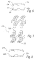
- the male element 123 is constituted by a cylindrical tab, which is suitable to enter a complementarily shaped seat which forms the female element 124.
- the cylindrical tab is fixed in the corresponding seat by means of an adhesive bonding operation or alternatively by means of an ultrasound welding operation.
- the assembly sequence is similar to what has been described for the first embodiment 10 of the invention, except for the application of the adhesive before joining the two half-shells 118 and 119 if the two half shells are joined by adhesive bonding.
- the male element 223 is constituted by a substantially prism-shaped tab, which is suitable to be arranged in a complementarily shaped seat, which in this case forms the female element 224.
- the prism-shaped tab is fixed to its seat by ultrasound welding or, as an alternative, by way of an adhesive bonding operation.
- the tabs and the corresponding seats are suitable to center the two half-shells or to facilitate the mutual arrangement, which is essential for the adhesive bonding and welding operations.
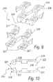
- a fourth embodiment of a modular covering element according to the invention is shown in Figures 9 and 10 and designated therein by the reference numeral 310, and is characterized in that the mating means 320 are constituted, for each connecting end 321 and 322 respectively, by a substantially flat surface 327 of the ends 321 of the first half-shell 318, which is fixed to the facing surface 328 of the opposite second half-shell 319 by way of an adhesive bonding operation or by way of an ultrasound welding operation.
- the present invention provides a modular covering element for bar-type conveyors which improves the fixing of the modular element to the bar without compromising its elastic qualities and functionality.
- the present invention provides a modular covering element that is easy to apply to the bars of a conveyor belt.
- the present invention provides a modular covering element which can also be applied to known types of bar conveyor which are already in use.
- the present invention provides a modular covering element for bar-type conveyors which can be manufactured at low cost with known systems and technologies.
- the materials employed may be any according to the requirements and the state of the art.
Landscapes
- Engineering & Computer Science (AREA)
- Mechanical Engineering (AREA)
- Chain Conveyers (AREA)
- Belt Conveyors (AREA)
Applications Claiming Priority (1)
| Application Number | Priority Date | Filing Date | Title |
|---|---|---|---|
| ITPD20040199 ITPD20040199A1 (it) | 2004-07-27 | 2004-07-27 | Struttura di modulo di copertura per trasportatori a barre |
Publications (1)
| Publication Number | Publication Date |
|---|---|
| EP1621484A1 true EP1621484A1 (en) | 2006-02-01 |
Family
ID=34981579
Family Applications (1)
| Application Number | Title | Priority Date | Filing Date |
|---|---|---|---|
| EP05106434A Withdrawn EP1621484A1 (en) | 2004-07-27 | 2005-07-14 | Replaceable snap-on modular overlay for rod and link turn-curve conveyor belts |
Country Status (2)
| Country | Link |
|---|---|
| EP (1) | EP1621484A1 (it) |
| IT (1) | ITPD20040199A1 (it) |
Cited By (1)
| Publication number | Priority date | Publication date | Assignee | Title |
|---|---|---|---|---|
| US11051519B2 (en) * | 2018-06-06 | 2021-07-06 | Werner & Pfleiderer Industrielle Backtechnik Gmbh | Endless conveyor belt for a conveyor baking oven and belt link for said endless conveyor belt |
Citations (3)
| Publication number | Priority date | Publication date | Assignee | Title |
|---|---|---|---|---|
| EP0502639A1 (en) * | 1991-02-22 | 1992-09-09 | Ashworth Bros. Inc. | Replaceable snap-on modular overlay for rod and link turn-curve conveyor belts |
| EP0894743A1 (en) * | 1997-08-01 | 1999-02-03 | TECNO POOL S.p.A. | Module of a conveyor belt and conveyor belt using this module |
| US20030024794A1 (en) * | 2001-08-06 | 2003-02-06 | Michael Etherington | Conveyor belt and method of assembly |
-
2004
- 2004-07-27 IT ITPD20040199 patent/ITPD20040199A1/it unknown
-
2005
- 2005-07-14 EP EP05106434A patent/EP1621484A1/en not_active Withdrawn
Patent Citations (3)
| Publication number | Priority date | Publication date | Assignee | Title |
|---|---|---|---|---|
| EP0502639A1 (en) * | 1991-02-22 | 1992-09-09 | Ashworth Bros. Inc. | Replaceable snap-on modular overlay for rod and link turn-curve conveyor belts |
| EP0894743A1 (en) * | 1997-08-01 | 1999-02-03 | TECNO POOL S.p.A. | Module of a conveyor belt and conveyor belt using this module |
| US20030024794A1 (en) * | 2001-08-06 | 2003-02-06 | Michael Etherington | Conveyor belt and method of assembly |
Cited By (1)
| Publication number | Priority date | Publication date | Assignee | Title |
|---|---|---|---|---|
| US11051519B2 (en) * | 2018-06-06 | 2021-07-06 | Werner & Pfleiderer Industrielle Backtechnik Gmbh | Endless conveyor belt for a conveyor baking oven and belt link for said endless conveyor belt |
Also Published As
| Publication number | Publication date |
|---|---|
| ITPD20040199A1 (it) | 2004-10-27 |
Similar Documents
| Publication | Publication Date | Title |
|---|---|---|
| US4159763A (en) | Inspectable modular conveyor | |
| EP1422171B1 (en) | Crossover conveyor chain device | |
| EP1890951B1 (en) | Modular conveyor belts and attachments | |
| US7802676B2 (en) | Conveyor belt module with high friction conveying surface | |
| EP2091848B1 (en) | Modular belt with gapless side guard | |
| JP3580415B2 (ja) | チェーン用ローラ及びローラを備えたチェーン | |
| US20030015406A1 (en) | Snap-on side guards | |
| US8371437B2 (en) | Module for a conveyor mat and modular conveyor mat | |
| DK2710280T3 (en) | Strap with a detachable end joint | |
| KR20090113176A (ko) | 케이블류 보호 안내 장치 | |
| JP2013047573A (ja) | フィンガ付き熱可塑性ベルトコネクタ | |
| JPH0318505A (ja) | 駆動用連結部を有するモジュール及び該モジュールより組立てられたコンベヤベルト | |
| JP2002114349A (ja) | 交互にオフセットされたクロスリブを有するモジュール | |
| GB842230A (en) | Endless chain conveyors | |
| EP1621484A1 (en) | Replaceable snap-on modular overlay for rod and link turn-curve conveyor belts | |
| US6640966B2 (en) | Guide structure with serpentine elements for the return section of endless conveyors | |
| EP1836113B1 (en) | Conveyor belt | |
| US7168557B2 (en) | Side-flexing conveyor chain having members joined by linkages | |
| CA1072907A (en) | Non-pivotal modular conveyor belt and modular links therefor | |
| EP1616817A1 (en) | Replaceable snap-on modular overlay for rod and link turn-curve conveyor belts | |
| US20060006051A1 (en) | Welded conveyor belt modules, belts made of welded modules, and method of making welded modules | |
| JP4237770B2 (ja) | 組立て式循環移送コンベア | |
| AU2001295707A1 (en) | Module for producing a conveyor belt | |
| WO2008020755A2 (en) | Chain module for a modular chain conveyor, modular conveyor and conveying system provided with a modular chain conveyor | |
| GB2153323A (en) | Curve-negotiating plate conveyor |
Legal Events
| Date | Code | Title | Description |
|---|---|---|---|
| PUAI | Public reference made under article 153(3) epc to a published international application that has entered the european phase |
Free format text: ORIGINAL CODE: 0009012 |
|
| AK | Designated contracting states |
Kind code of ref document: A1 Designated state(s): AT BE BG CH CY CZ DE DK EE ES FI FR GB GR HU IE IS IT LI LT LU LV MC NL PL PT RO SE SI SK TR |
|
| AX | Request for extension of the european patent |
Extension state: AL BA HR MK YU |
|
| RAP1 | Party data changed (applicant data changed or rights of an application transferred) |
Owner name: ALIT S.R.L. |
|
| 17P | Request for examination filed |
Effective date: 20060713 |
|
| GRAP | Despatch of communication of intention to grant a patent |
Free format text: ORIGINAL CODE: EPIDOSNIGR1 |
|
| AKX | Designation fees paid |
Designated state(s): AT BE BG CH CY CZ DE DK EE ES FI FR GB GR HU IE IS IT LI LT LU LV MC NL PL PT RO SE SI SK TR |
|
| STAA | Information on the status of an ep patent application or granted ep patent |
Free format text: STATUS: THE APPLICATION IS DEEMED TO BE WITHDRAWN |
|
| 18D | Application deemed to be withdrawn |
Effective date: 20070123 |