EP1621511A2 - Verriegelungs- und Entriegelungsvorrichtung für Aufzugsschachttüren - Google Patents
Verriegelungs- und Entriegelungsvorrichtung für Aufzugsschachttüren Download PDFInfo
- Publication number
- EP1621511A2 EP1621511A2 EP05291469A EP05291469A EP1621511A2 EP 1621511 A2 EP1621511 A2 EP 1621511A2 EP 05291469 A EP05291469 A EP 05291469A EP 05291469 A EP05291469 A EP 05291469A EP 1621511 A2 EP1621511 A2 EP 1621511A2
- Authority
- EP
- European Patent Office
- Prior art keywords
- lever
- unlocking
- movable cam
- locking
- door
- Prior art date
- Legal status (The legal status is an assumption and is not a legal conclusion. Google has not performed a legal analysis and makes no representation as to the accuracy of the status listed.)
- Withdrawn
Links
- 238000000034 method Methods 0.000 claims abstract description 7
- 230000035515 penetration Effects 0.000 claims description 4
- 230000003111 delayed effect Effects 0.000 claims description 3
- 238000006073 displacement reaction Methods 0.000 description 5
- 241000287107 Passer Species 0.000 description 1
- 238000013459 approach Methods 0.000 description 1
- 230000001174 ascending effect Effects 0.000 description 1
- 230000000694 effects Effects 0.000 description 1
- 238000009434 installation Methods 0.000 description 1
- 238000005096 rolling process Methods 0.000 description 1
Images



Classifications
-
- B—PERFORMING OPERATIONS; TRANSPORTING
- B66—HOISTING; LIFTING; HAULING
- B66B—ELEVATORS; ESCALATORS OR MOVING WALKWAYS
- B66B13/00—Doors, gates, or other apparatus controlling access to, or exit from, cages or lift well landings
- B66B13/02—Door or gate operation
- B66B13/14—Control systems or devices
- B66B13/16—Door or gate locking devices controlled or primarily controlled by condition of cage, e.g. movement or position
- B66B13/18—Door or gate locking devices controlled or primarily controlled by condition of cage, e.g. movement or position without manually-operable devices for completing locking or unlocking of doors
- B66B13/20—Lock mechanisms actuated mechanically by abutments or projections on the cages
Definitions
- the invention relates to a locking and unlocking device for lift landing doors, in particular for elevator swing doors.
- the invention also relates to an elevator assembly comprising such a device, and to a method of unlocking an elevator landing door with the aid of such a device. It finds application in the field of the safe opening and closing of elevator swing doors.
- the patent application FR-A-2 761 967 describes a device for locking and unlocking elevator landing doors.
- Each door is equipped with a lever mounted movably between a locking position and an unlocking position and the locking / unlocking device comprises, a control element of the lever mounted on the cab and which acts on it when the cab is located at a corresponding level.
- the driving element takes the form of a movable bridge which abuts against the lever when the cabin is on the desired floor, thus causing the rotation of the lever.
- the lever is connected to a bolt of the elevator door and the rotation of the lever causes the bolt to move, resulting in the unlocking of the door.
- the movable member moves away from the lever, it returns to its initial position under the action of the spring of the bolt that comes to condemn the door.
- This device is totally secure if the lever is not accessible from the cabin or the landing. But it can happen that people can reach the lever, for example using a hook, and pulling it, they trigger the unlocking mechanism of the door and manage to open the door even in the no cabin at the landing. When the door is thus unlocked, a person can open the door even in the absence of a cabin, and it can fall into the elevator duct.
- An object of the present invention is to provide a locking and unlocking device for elevator landing doors which does not have the drawbacks of the prior art.
- the securing means comprises a ratchet secured to the second lever, the first lever comprises an orifice and the securing of the first lever and the second lever is achieved by penetration of the pawl into the orifice.
- the second lever rests on a stop of the first lever under the action of its weight when the second lever is not actuated by the movable cam.
- the securing means comprises a pressure means adapted to penetrate the pawl into the orifice during the fastening.
- the pawl has a sliding surface of the pressure means.
- the sliding surface is an ascending slope between the contact zone of the pressure means in the unlocked position and the contact zone of the pressure means in the locked position.
- the pressure means is a hammer secured to a third lever adapted to be actuated by the movable cam as it moves from its locking position to its unlocking position.
- the second lever and the third lever form with each other an angle that expands when the movable cam passes from its locking position to its unlocking position.
- the angle is made by a torsion spring whose one arm is fixed to the second lever and whose second arm is fixed to the third lever.
- the delay of the actuation delay is adjustable by the angle formed between them the two arms of the spring, when the cam is in the locking position.
- the delay of the actuation delay is adjustable by adjusting the position of the hammer on the third lever.
- the landing door is a manual door.
- the door is a swing door.
- a lift assembly consists of a duct in which a cabin travels, to allow access to the cabin, it stops at the various levels served and boarding or disembarking.
- the cabin is made by landing doors which open at the level of the bearings.
- the landing doors can be manual or automatic hinged doors
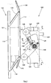
- Fig. 1 shows a device 100 for locking and unlocking elevator landing doors in a locking position of the landing door.
- the cab is provided with a movable cam 106 which can move from a first position, shown in FIG. 1, said locking the door and a second position, shown in FIG. 4, called unlocking the door.
- the movable cam 106 comprises a base 101 fixed on the wall of the cabin and a bearing surface 112 delimited by a lower slope 110 and an upper slope 108.
- the base 101 and the bearing surface 112 are connected by two pivoting arms 116, 118.
- the movable cam 106 also includes an actuator 114 which acts on the lower pivoting arm 118 via a telescopic arm.
- the cabin switches a switch that controls the actuator 114, the telescopic arm deploys and the pivoting arms 116, 118 pivot by driving the bearing surface 112 which passes from the lock position at the unlock position.
- the locking / unlocking device 100 is generally fixed to the frame of the landing door and comprises a lock 102 provided with a bolt 104 which passes from a locking position to an unlocked position of the door when entering the door. body of the lock 102.
- the bolt 104 comes into a housing provided on the door to lock the door and out of this housing to unlock.
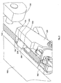
- the bolt 104 is controlled in translation by a shaft 302 (FIG 7) of axis referenced 130, in the direction of rotation of the shaft 302, the bolt enters the housing or out of the housing.
- the shaft 302 is rigidly connected to a first lever 132.
- the first lever 132 thus pivots around the axis 130 and drives the bolt between its locking position and its unlocking position via the shaft 302.
- the device 100 of locking / unlocking also comprises a second lever 124 provided at one of these ends with a roller 126 and whose other end pivots about the axis 130.
- the second lever 124 is mounted crazy on the first lever 132, that is to say that it rotates freely about the axis 130 independently of the movement of the first lever 132.
- the second lever 124 is engaged on a cylinder 804 (FIG 7) of the first lever 132 and is locked in translation in the direction of the axis 130 by a circlip 802.
- a securing means is provided for securing the first lever 132 and the second lever 124 when the movable cam 106 passes from its locking position to its unlocking position. Way to a fastening of which an exemplary embodiment is given below, is controlled by the movable cam 106.
- the first lever 132 is provided to be difficult to access from the outside, in the example it is pressed against the second lever 124 which thus conceals it and it has no roughness that can be hooked by hooks, unlike the second lever 124 which can easily be hung by its pebble 126.
- the securing means is provided for separating the first lever 132 and the second lever 124 when the movable cam 106 moves from its unlocking position to its locking position, thus releasing the first lever 132 of the second lever 124 and making thus the fraudulent opening of the door difficult.
- the securing means comprises a pawl 134 integral with the second lever 124, for example by means of a screw-nut system 136.
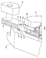
- Fig. 2 shows the second lever 124 on which is fixed the pawl 134 which comprises a body 210 and a flexible tongue 208 connecting the body to the point of attachment of the pawl 134.
- the first lever 132 comprises an orifice 206 into which the body 210 of the pawl 134 engages in order to fasten the first lever 132 and the second lever 124.
- the penetration of the pawl 134 into the orifice 206 whose dimensions are slightly greater than the dimensions of the pawl 134 binds the displacement of the first lever 132 to the displacement of the second lever 124, when the movable cam 106 presses on the roller 126.
- the second lever 124 has an orifice 204 which allows the passage of the body 210 of the pawl 134 during the securing, but this orifice has no function related to the fastening and the pawl 134 can be deported relative to the body the second lever 124.
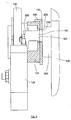
- Fig. 3 shows the device in the locking position.
- the pawl 134 is in position inside the orifice 204 of the second lever 124, but its lower surface 304 does not penetrate into the orifice 206 of the first lever 132, thus preventing any movement of the first lever 124 when the second lever 124 is fraudulently operated.
- the securing means comprises a pressing means 128 which presses on the pawl 134 when the first lever 132 is secured to the second lever 124.
- Pressurization of the pawl 134 by the pressing means 128 is performed by a sliding surface 202 of the pawl 134 which allows the pressure means 128 to slide on the pawl 134.
- the sliding surface 202 is a slope which has an angle with respect to the plane in which the pressure means 128 moves. The slope 202 is upwardly between the contact zone of the pressure means 128 in the unlocking position and the zone contacting the pressure means 128 in the locking position. As can be seen in FIG.
- the slope 202 rises between the contact zone of the pressure means 128 in the unlocked position and the contact zone of the pressure means 128 in the locked position and plays a wedge role which when subjected to the action the pressure means 128 moves by driving the body 210 of the pawl 134.
- the pressure means 128 and the slope 202 are positioned so that when the pressure means moves, it is placed on the slope 202 and does not hit the side of the body 210 of the pawl 134.
- the slope 202 extends on either side of the contact zone of the pressure means 128 on the slope 202 in position unlocking.
- the pressure means may take the form of a hammer 128 integral with a third lever 120 mounted to rotate freely about the axis 130.
- FIG. 7 shows a particular arrangement of the various elements in which the third lever 120 is fitted on the cylinder 804 of the first lever 132 and is locked in translation in the direction of the axis 130 by the circlip 802. Any attempt to open by manipulation of the third lever 120 will fail, because the displacement of the third lever 120 will cause the attachment of the first lever 132 and the second lever 124 but the door will not be unlocked because there will be no rotational force exerted on the first lever 132.
- the third lever 120 is provided with a roller 122 which serves as contact between the third lever 120 and the movable cam 106 as it moves from its locking position to its unlocking position.
- the unlocking mechanism will be more particularly described in relation to FIGS. 4-6.
- the actuator 114 deploys the telescopic arm which pushes the bearing surface 112 which thus hits the roller 122 of the third lever 120 and the roller 126 of the second lever 124.
- the third lever 120 causes the movement of the hammer 128 which hits the body 210 of the pawl 134 whose tab 208 plic, thereby causing the penetration of the pawl 134 in the hole 206 of the first lever 132.
- the lower surface 304 of the pawl 134 passes through the orifice 206, thereby making the first lever 132 and the second lever 124 integral.
- the second lever 124 When the roller 126 of the second lever 124 is driven by the movable cam 106, the second lever 124 then pivots about the axis 130 by driving the pawl 134 which is fitted into the first lever 132. The pawl 134 then hits the walls. of the orifice 206 and the first lever 132 is driven by the pawl 134. The rotation of the first lever 132 then causes the rotation of the shaft 302 which actuates the bolt 104 which retracts, thus unlocking the door.
- the third lever 120 rotates counter-clockwise about the axis 130 to actuate the pawl 134, while the second lever 124 rotates clockwise about the axis 130 to actuate the bolt 104.
- the second lever 124 and the third lever 120 thus form with each other an angle ⁇ between 0 and 180 ° which expands when the movable cam 106 moves from its locking position to its unlocked position.
- the angle ⁇ is preferably between 100 and 120 degrees.
- the second lever 124 and the third lever 120 has an angle different from 90 ° relative to the bearing surface 112 to facilitate the rolling of the rollers 1.22, 126 on the bearing surface 112 and preferably the second lever 124 and the third lever 120 are arranged on either side of the plane normal to the bearing surface 112 and passing through the axis 130.
- a person who attempts to fraudulently open the door must therefore, on the one hand pulling the third lever 120 in a first direction and secondly pulling the second lever 124 in a second direction.
- a torsion spring can be put in place.
- the torsion spring is such that one of the arms is fixed to the second lever 124 and the second arm is attached to the third lever 120, the axis of the spring then being substantially at the axis 130. of this spring thus maintains the angle ⁇ between, on the one hand, the second lever 124 which is positioned by the abutment 306 and which undergoes the action of its weight and, on the other hand, the third lever 120 which is supported by the second arm of the spring.
- the actuation by the movable cam 106 of the second lever 1.24 is delayed with respect to the actuation of the securing device, so that the securing device is engaged before the actuation of the second lever 124 which releases the bolt 104.
- the delay of the actuation delay between the second lever 124 and the securing device is adjustable by the angle ⁇ that form between them the two arms of the spring, when the cam 106 is in the locking position. Indeed, the position of the second lever 124 being constrained by the first lever 132, plus the angle ⁇ between the second lever 124 and the third lever 120 is small, the third lever 120 is closer to the second lever 124 and the roller 122 of the third lever 120 approaches the movable cam 106.
- the delay time may be adjustable by changing the length of the levers, but this is not industrially advantageous.
- the delay may also be adjustable by adjusting the position of the hammer 128 on the third lever 120.
- An elevator assembly generally comprises at least one landing door placed in a frame fixed on the walls of the landing and a cabin.
- the car is provided with the movable cam 106 which is activated when the car stops at the selected landing.
- the frame of the door is provided with the device 100 for locking / unlocking which makes it possible to lock the door by cooperation between the bolt 104 and a housing of the door.
- the device 100 of locking / unlocking can be positioned on the door and the bolt then cooperates with a housing of the frame.
- the landing door can be an automatic or manual door, and is preferably swinging.
- the device 100 for locking / unlocking can be placed on one of the vertical uprights or on one of the horizontal portions of the door or the frame.
- the unlocking method comprises a step of stopping the cabin in front of the landing door; a step of actuating the securing means by the movable cam 106; a step of actuating the first lever 132 by the movable cam 106; and a step of unlocking the bolt 104 by action of the first lever 132.
- the movable cam 106 moves towards the rollers 122, 126.
- the movable cam 106 pushes the roller 122 of the third lever 120 which pivots and whose hammer 128 actuates the pawl 134.
- the pawl 134 then enters the orifice 206 of the first lever 132 which thus becomes integral with the second lever 124.
- the movable cam 106 then pushes the roller 126 of the second lever 124 which pivots and which drives the first lever 132 in rotation thereby causing the bolt that retracts and unlocks the door.
- the second lever 124 and the third lever 120 moves relative to each other so that the angle ⁇ between them expands, the torsion spring is then energized.
- the movable cam 106 When the door must be locked before moving the cabin, the movable cam 106 returns to its initial position by first releasing the second lever 124 which remains integral with the first lever 132, the two levers 124, 132 are repositioned in the initial position under the effect of the return of the bolt 104 in the locking position.
- the spring which is still under tension retains the third lever 120 which is pressed against the movable cam 106.
- the third lever 120 is then released and returns to its initial angular position relative to the second lever 124 which is simultaneously disengaged from the first lever 132. spring then returns to its original shape.
- the securing means may be an electromechanical device of the electromagnet type equipped with a switch. Under the action of the moving cam, the switch will come to activate the electromagnet which will come to secure the first lever and the second lever, for example by positioning a rod in the hole of the first lever, the rod then plays the role ratchet.
Landscapes
- Engineering & Computer Science (AREA)
- Mechanical Engineering (AREA)
- Automation & Control Theory (AREA)
- Elevator Door Apparatuses (AREA)
Applications Claiming Priority (1)
| Application Number | Priority Date | Filing Date | Title |
|---|---|---|---|
| FR0408264A FR2873669A1 (fr) | 2004-07-27 | 2004-07-27 | Dispositif de verrouillage et de deverrouillage pour portes palieres d'ascenseur |
Publications (2)
| Publication Number | Publication Date |
|---|---|
| EP1621511A2 true EP1621511A2 (de) | 2006-02-01 |
| EP1621511A3 EP1621511A3 (de) | 2006-05-17 |
Family
ID=34952453
Family Applications (1)
| Application Number | Title | Priority Date | Filing Date |
|---|---|---|---|
| EP05291469A Withdrawn EP1621511A3 (de) | 2004-07-27 | 2005-07-06 | Verriegelungs- und Entriegelungsvorrichtung für Aufzugsschachttüren |
Country Status (2)
| Country | Link |
|---|---|
| EP (1) | EP1621511A3 (de) |
| FR (1) | FR2873669A1 (de) |
Cited By (6)
| Publication number | Priority date | Publication date | Assignee | Title |
|---|---|---|---|---|
| EP1894878A1 (de) * | 2006-08-29 | 2008-03-05 | Thyssenkrupp Elevator Manufacturing France S.A.S. | Locking and unlocking device for a lever of an elevator landing door |
| FR2981384A1 (fr) * | 2011-10-17 | 2013-04-19 | Prudhomme Sa | Came de deverrouillage de porte paliere d'ascenseur et son utilisation |
| CN104326348A (zh) * | 2014-10-22 | 2015-02-04 | 杭州西奥电梯有限公司 | 一种带有锁定装置的前沿板 |
| US10710843B2 (en) | 2015-08-04 | 2020-07-14 | Otis Elevator Company | Car door interlock with sill lock |
| US10882720B2 (en) | 2015-08-04 | 2021-01-05 | Otis Elevator Company | Elevator car door interlock |
| CN116142930A (zh) * | 2022-12-06 | 2023-05-23 | 杭州优迈机电科技有限公司 | 门锁装置及电梯门机 |
Citations (1)
| Publication number | Priority date | Publication date | Assignee | Title |
|---|---|---|---|---|
| FR2761967A1 (fr) | 1997-04-15 | 1998-10-16 | Thyssen Ascenseurs | Dispositif de commande de verrouillage et de deverrouillage de portes palieres d'un ascenseur |
Family Cites Families (3)
| Publication number | Priority date | Publication date | Assignee | Title |
|---|---|---|---|---|
| DE731720C (de) * | 1941-03-22 | 1943-02-13 | Stahl R Fa | Schachttuerverriegelungsvorrichtung bei Aufzuegen |
| BR9101160A (pt) * | 1991-03-25 | 1992-11-17 | Elevadores Otis Ltda | Sistema de seguranca para travamento de uma porta batente de elevador |
| FR2827265B1 (fr) * | 2001-07-12 | 2003-12-12 | Tegur | Dispositif de verrouillage d'une porte paliere a deverrouillage de secours independant |
-
2004
- 2004-07-27 FR FR0408264A patent/FR2873669A1/fr active Pending
-
2005
- 2005-07-06 EP EP05291469A patent/EP1621511A3/de not_active Withdrawn
Patent Citations (1)
| Publication number | Priority date | Publication date | Assignee | Title |
|---|---|---|---|---|
| FR2761967A1 (fr) | 1997-04-15 | 1998-10-16 | Thyssen Ascenseurs | Dispositif de commande de verrouillage et de deverrouillage de portes palieres d'un ascenseur |
Cited By (10)
| Publication number | Priority date | Publication date | Assignee | Title |
|---|---|---|---|---|
| EP1894878A1 (de) * | 2006-08-29 | 2008-03-05 | Thyssenkrupp Elevator Manufacturing France S.A.S. | Locking and unlocking device for a lever of an elevator landing door |
| FR2981384A1 (fr) * | 2011-10-17 | 2013-04-19 | Prudhomme Sa | Came de deverrouillage de porte paliere d'ascenseur et son utilisation |
| EP2583930A1 (de) * | 2011-10-17 | 2013-04-24 | Prudhomme Sas | Entriegelungszunge einer Etagentür eines Aufzugs und ihre Verwendung |
| CN104326348A (zh) * | 2014-10-22 | 2015-02-04 | 杭州西奥电梯有限公司 | 一种带有锁定装置的前沿板 |
| CN104326348B (zh) * | 2014-10-22 | 2016-10-05 | 杭州西奥电梯有限公司 | 一种带有锁定装置的前沿板 |
| US10710843B2 (en) | 2015-08-04 | 2020-07-14 | Otis Elevator Company | Car door interlock with sill lock |
| US10882720B2 (en) | 2015-08-04 | 2021-01-05 | Otis Elevator Company | Elevator car door interlock |
| US11124389B2 (en) | 2015-08-04 | 2021-09-21 | Otis Elevator Company | Elevator car door interlock |
| US11795033B2 (en) | 2015-08-04 | 2023-10-24 | Otis Elevator Company | Elevator car door interlock |
| CN116142930A (zh) * | 2022-12-06 | 2023-05-23 | 杭州优迈机电科技有限公司 | 门锁装置及电梯门机 |
Also Published As
| Publication number | Publication date |
|---|---|
| FR2873669A1 (fr) | 2006-02-03 |
| EP1621511A3 (de) | 2006-05-17 |
Similar Documents
| Publication | Publication Date | Title |
|---|---|---|
| EP3456579B1 (de) | Gleitschiene für fahrzeugsitz, und fahrzeugsitz, der eine solche gleitschiene umfasst | |
| FR2823495A1 (fr) | Dispositif de couplage entre les portes de cabine et les portes palieres d'un ascenseur, avec securite d'ouverture | |
| FR2725190A1 (fr) | Dispositif de liaison d'une porte de cabine d'ascenseur et d'une porte de palier pour leur ouverture et fermeture synchrones | |
| EP1621511A2 (de) | Verriegelungs- und Entriegelungsvorrichtung für Aufzugsschachttüren | |
| EP1404605B1 (de) | Verriegelungsvorrichtung für schachttür mit unabhängiger notentriegelungsvorrichtung | |
| EP1845054A1 (de) | Vorrichtung zur Verriegelung eines ausfallsicheren Schlosses, insbesondere für eine Etagentür eines Aufzugs, und diese Vorrichtung enthaltendes Schloss | |
| EP2780209B1 (de) | Mechanisches hubfahrzeug | |
| EP1031689B1 (de) | Steuervorrichtung für eine Tür mit einer aktiv verriegelbaren Notausgangsgriffstange | |
| EP0314565A1 (de) | Vorrichtung zum Verschliessen des oberen Zugangs eines senkrechten rohrförmigen Schachtes | |
| FR2540170A1 (fr) | Mecanisme de cremone-serrure de securite a double condamnation pour porte d'entree ou porte paliere | |
| FR2523939A1 (fr) | Dispositif de verrouillage pour empecher l'ouverture de la porte d'une cabine d'ascenseur entre les etages | |
| EP0802143B1 (de) | Mechanische Sicherheitsvorrichtung für den Benutzer eines Aufzuges zwischen zwei Stockwerken | |
| EP1023513B1 (de) | Sicherheitsschloss, insbesondere für aufzugsschachttür | |
| EP1943176B1 (de) | Gesicherte einrichtung für einen aufzug | |
| EP1355031A1 (de) | Verriegelungsvorrichtung für ein motorisiertes Tor | |
| FR2869340A1 (fr) | Dispositif d'ouverture d'un ouvrant de vehicule automobile muni de moyens pour empecher l'ouverture de l'ouvrant en cas de choc lateral | |
| FR2934300A1 (fr) | Dispositif entrebailleur pour ouvrant | |
| EP1800536B1 (de) | Türkontrolleinrichtung für Vieh mit automatischer Schliessvorrichtung | |
| FR2725470A1 (fr) | Dispositif de serrure a verrouillage et a condamnation automatiques et a deverrouillage assiste | |
| FR2753224A1 (fr) | Serrure electromagnetique pour porte a ouverture telecommandee | |
| FR2845111A1 (fr) | Arret de battant, notamment arret de porte | |
| EP2660414B1 (de) | Sicherheitsschleusenvorrichtung | |
| EP0424288B1 (de) | Türverriegelung und Türrahmen mit solcher Verriegelung | |
| EP1808559B1 (de) | LKW mit einer Verriegelungsvorrichtung für zumindest eine Tür eines Raums. | |
| FR2666839A1 (fr) | Systeme de desenfumage pour facades de batiment. |
Legal Events
| Date | Code | Title | Description |
|---|---|---|---|
| PUAI | Public reference made under article 153(3) epc to a published international application that has entered the european phase |
Free format text: ORIGINAL CODE: 0009012 |
|
| AK | Designated contracting states |
Kind code of ref document: A2 Designated state(s): AT BE BG CH CY CZ DE DK EE ES FI FR GB GR HU IE IS IT LI LT LU LV MC NL PL PT RO SE SI SK TR |
|
| AX | Request for extension of the european patent |
Extension state: AL BA HR MK YU |
|
| PUAL | Search report despatched |
Free format text: ORIGINAL CODE: 0009013 |
|
| AK | Designated contracting states |
Kind code of ref document: A3 Designated state(s): AT BE BG CH CY CZ DE DK EE ES FI FR GB GR HU IE IS IT LI LT LU LV MC NL PL PT RO SE SI SK TR |
|
| AX | Request for extension of the european patent |
Extension state: AL BA HR MK YU |
|
| AKX | Designation fees paid | ||
| REG | Reference to a national code |
Ref country code: DE Ref legal event code: 8566 |
|
| STAA | Information on the status of an ep patent application or granted ep patent |
Free format text: STATUS: THE APPLICATION IS DEEMED TO BE WITHDRAWN |
|
| 18D | Application deemed to be withdrawn |
Effective date: 20061118 |