EP1621670A2 - Procédé de construction d'une voie ferrée et voie ferrée - Google Patents
Procédé de construction d'une voie ferrée et voie ferrée Download PDFInfo
- Publication number
- EP1621670A2 EP1621670A2 EP05016058A EP05016058A EP1621670A2 EP 1621670 A2 EP1621670 A2 EP 1621670A2 EP 05016058 A EP05016058 A EP 05016058A EP 05016058 A EP05016058 A EP 05016058A EP 1621670 A2 EP1621670 A2 EP 1621670A2
- Authority
- EP
- European Patent Office
- Prior art keywords
- rail support
- rail
- layer
- support structure
- support structures
- Prior art date
- Legal status (The legal status is an assumption and is not a legal conclusion. Google has not performed a legal analysis and makes no representation as to the accuracy of the status listed.)
- Withdrawn
Links
- 238000010276 construction Methods 0.000 title claims description 22
- 238000000034 method Methods 0.000 title claims description 21
- 238000004519 manufacturing process Methods 0.000 claims abstract description 22
- 229920001169 thermoplastic Polymers 0.000 claims abstract description 12
- 239000004416 thermosoftening plastic Substances 0.000 claims abstract description 12
- 230000015572 biosynthetic process Effects 0.000 claims abstract description 5
- 239000004567 concrete Substances 0.000 claims description 33
- 239000002131 composite material Substances 0.000 claims description 28
- 239000000463 material Substances 0.000 claims description 16
- 230000008093 supporting effect Effects 0.000 claims description 16
- 239000011230 binding agent Substances 0.000 claims description 12
- 239000010426 asphalt Substances 0.000 claims description 9
- 238000007906 compression Methods 0.000 claims description 8
- 238000005339 levitation Methods 0.000 claims description 7
- 230000009471 action Effects 0.000 claims description 6
- 238000000465 moulding Methods 0.000 claims description 6
- 241000283690 Bos taurus Species 0.000 claims description 4
- XEEYBQQBJWHFJM-UHFFFAOYSA-N Iron Chemical compound [Fe] XEEYBQQBJWHFJM-UHFFFAOYSA-N 0.000 claims description 4
- 150000001875 compounds Chemical class 0.000 claims description 4
- 230000006835 compression Effects 0.000 claims description 4
- 239000000203 mixture Substances 0.000 claims description 4
- 230000004888 barrier function Effects 0.000 claims description 3
- 230000002787 reinforcement Effects 0.000 claims description 3
- 229910052742 iron Inorganic materials 0.000 claims description 2
- 230000003068 static effect Effects 0.000 claims description 2
- 239000011148 porous material Substances 0.000 claims 2
- 238000000280 densification Methods 0.000 claims 1
- 244000144972 livestock Species 0.000 claims 1
- 238000005755 formation reaction Methods 0.000 abstract 3
- 230000000694 effects Effects 0.000 description 18
- 238000013461 design Methods 0.000 description 11
- 239000004033 plastic Substances 0.000 description 10
- 239000000853 adhesive Substances 0.000 description 7
- 230000001070 adhesive effect Effects 0.000 description 7
- 238000012423 maintenance Methods 0.000 description 7
- 229910000831 Steel Inorganic materials 0.000 description 6
- 230000008569 process Effects 0.000 description 6
- 239000010959 steel Substances 0.000 description 6
- VYPSYNLAJGMNEJ-UHFFFAOYSA-N Silicium dioxide Chemical compound O=[Si]=O VYPSYNLAJGMNEJ-UHFFFAOYSA-N 0.000 description 5
- 230000002829 reductive effect Effects 0.000 description 5
- 230000008439 repair process Effects 0.000 description 5
- 230000008901 benefit Effects 0.000 description 4
- 238000005056 compaction Methods 0.000 description 4
- 230000001419 dependent effect Effects 0.000 description 4
- 238000011161 development Methods 0.000 description 4
- 230000018109 developmental process Effects 0.000 description 4
- 238000006073 displacement reaction Methods 0.000 description 4
- 238000009826 distribution Methods 0.000 description 4
- 238000005452 bending Methods 0.000 description 3
- 239000000835 fiber Substances 0.000 description 3
- 239000004576 sand Substances 0.000 description 3
- 239000002689 soil Substances 0.000 description 3
- 239000007787 solid Substances 0.000 description 3
- XLYOFNOQVPJJNP-UHFFFAOYSA-N water Substances O XLYOFNOQVPJJNP-UHFFFAOYSA-N 0.000 description 3
- 241001669679 Eleotris Species 0.000 description 2
- 239000006004 Quartz sand Substances 0.000 description 2
- 230000005540 biological transmission Effects 0.000 description 2
- 238000005516 engineering process Methods 0.000 description 2
- 230000005284 excitation Effects 0.000 description 2
- 230000009969 flowable effect Effects 0.000 description 2
- 230000020169 heat generation Effects 0.000 description 2
- 230000008018 melting Effects 0.000 description 2
- 238000002844 melting Methods 0.000 description 2
- 230000007935 neutral effect Effects 0.000 description 2
- 230000008707 rearrangement Effects 0.000 description 2
- 238000009418 renovation Methods 0.000 description 2
- 238000003860 storage Methods 0.000 description 2
- 238000012546 transfer Methods 0.000 description 2
- 244000207740 Lemna minor Species 0.000 description 1
- 235000006439 Lemna minor Nutrition 0.000 description 1
- 241001465754 Metazoa Species 0.000 description 1
- 235000001855 Portulaca oleracea Nutrition 0.000 description 1
- 238000010521 absorption reaction Methods 0.000 description 1
- 230000002411 adverse Effects 0.000 description 1
- 230000002528 anti-freeze Effects 0.000 description 1
- 239000011384 asphalt concrete Substances 0.000 description 1
- 239000004566 building material Substances 0.000 description 1
- 239000013590 bulk material Substances 0.000 description 1
- 239000000969 carrier Substances 0.000 description 1
- 238000012937 correction Methods 0.000 description 1
- 238000012938 design process Methods 0.000 description 1
- 229920001971 elastomer Polymers 0.000 description 1
- 239000000806 elastomer Substances 0.000 description 1
- 230000003628 erosive effect Effects 0.000 description 1
- 230000002349 favourable effect Effects 0.000 description 1
- 238000007667 floating Methods 0.000 description 1
- 230000004907 flux Effects 0.000 description 1
- 239000011381 foam concrete Substances 0.000 description 1
- 238000009415 formwork Methods 0.000 description 1
- 238000011065 in-situ storage Methods 0.000 description 1
- 238000009434 installation Methods 0.000 description 1
- 238000009413 insulation Methods 0.000 description 1
- JEIPFZHSYJVQDO-UHFFFAOYSA-N iron(III) oxide Inorganic materials O=[Fe]O[Fe]=O JEIPFZHSYJVQDO-UHFFFAOYSA-N 0.000 description 1
- 230000009916 joint effect Effects 0.000 description 1
- 230000002045 lasting effect Effects 0.000 description 1
- 230000007774 longterm Effects 0.000 description 1
- 239000012528 membrane Substances 0.000 description 1
- 238000003801 milling Methods 0.000 description 1
- 239000011368 organic material Substances 0.000 description 1
- 230000000149 penetrating effect Effects 0.000 description 1
- 230000035699 permeability Effects 0.000 description 1
- 229920006327 polystyrene foam Polymers 0.000 description 1
- 238000004382 potting Methods 0.000 description 1
- 230000036316 preload Effects 0.000 description 1
- 238000002360 preparation method Methods 0.000 description 1
- 239000011513 prestressed concrete Substances 0.000 description 1
- 238000012545 processing Methods 0.000 description 1
- 230000000750 progressive effect Effects 0.000 description 1
- 230000005855 radiation Effects 0.000 description 1
- 239000011150 reinforced concrete Substances 0.000 description 1
- 230000003014 reinforcing effect Effects 0.000 description 1
- 230000002441 reversible effect Effects 0.000 description 1
- 238000005096 rolling process Methods 0.000 description 1
- 235000019592 roughness Nutrition 0.000 description 1
- 238000007789 sealing Methods 0.000 description 1
- 230000035945 sensitivity Effects 0.000 description 1
- 238000007711 solidification Methods 0.000 description 1
- 230000008023 solidification Effects 0.000 description 1
- 239000010902 straw Substances 0.000 description 1
- 239000002352 surface water Substances 0.000 description 1
- 238000005496 tempering Methods 0.000 description 1
- 230000002123 temporal effect Effects 0.000 description 1
- 230000036962 time dependent Effects 0.000 description 1
- 235000012773 waffles Nutrition 0.000 description 1
- 239000002023 wood Substances 0.000 description 1
Images

Classifications
-
- E—FIXED CONSTRUCTIONS
- E01—CONSTRUCTION OF ROADS, RAILWAYS, OR BRIDGES
- E01B—PERMANENT WAY; PERMANENT-WAY TOOLS; MACHINES FOR MAKING RAILWAYS OF ALL KINDS
- E01B19/00—Protection of permanent way against development of dust or against the effect of wind, sun, frost, or corrosion; Means to reduce development of noise
- E01B19/003—Means for reducing the development or propagation of noise
-
- E—FIXED CONSTRUCTIONS
- E01—CONSTRUCTION OF ROADS, RAILWAYS, OR BRIDGES
- E01B—PERMANENT WAY; PERMANENT-WAY TOOLS; MACHINES FOR MAKING RAILWAYS OF ALL KINDS
- E01B1/00—Ballastway; Other means for supporting the sleepers or the track; Drainage of the ballastway
- E01B1/002—Ballastless track, e.g. concrete slab trackway, or with asphalt layers
-
- E—FIXED CONSTRUCTIONS
- E01—CONSTRUCTION OF ROADS, RAILWAYS, OR BRIDGES
- E01B—PERMANENT WAY; PERMANENT-WAY TOOLS; MACHINES FOR MAKING RAILWAYS OF ALL KINDS
- E01B25/00—Tracks for special kinds of railways
- E01B25/30—Tracks for magnetic suspension or levitation vehicles
- E01B25/305—Rails or supporting constructions
Definitions
- the invention relates to a track for rail vehicles, especially for iron and magnetic levitation and a method for its preparation according to the preamble of claim 1.
- Railways of the type according to the invention are known for railways as slab track and for magnetic levitation as a ground floor driveway.
- the rails consist of functional plane carriers which are essentially composed of the functional levels of side guide rail, sliding strip and stator arrangement.
- the classic ballast track in railways is basically the ideal structure for the static-dynamic loads from rail traffic and the local constraints.
- the track grid of rails and sleepers, together with the permanently redeployable ballast, is an investment-cost-effective composite elastics composite vault with large mass.
- the ability of the ballast to relocate allows the structure to withstand even extreme loads caused by heavy loads, vibrations and centrifugal forces as well as constraints due to thermal cycles and deformations of the substructure. This advantage of the rearrangement is at the same time his biggest disadvantage, since the rearrangement of crushed grains is summarily always associated with deformations of an order that are not compatible with a required positional accuracy of the rails in the long run.
- the superstructure originally consisted of a polystyrene foam concrete slab, which is concreted on a relatively thin hydraulically bound upper soil layer of the substructure, a concrete reinforced concrete support slab and concreted on this concrete layer by means of spindles accurately aligned track grid of concrete sleepers and rails, by filling the gaps between base layer and thresholds is combined with filled concrete up to the upper edge of the sleepers to the monolithic structure of the superstructure. If one adds the upper hydraulically bound support layer of the substructure to the monolithic structure, the result is a track structure with high rigidity, vaults and mass, as is desirable for the formation of a rail track with respect to consistently high positional accuracy of the track and high resistance to vibration load by rail.
- a disadvantage of this design are the high investment costs and the cost and time-consuming production and maintenance of rail travel.
- both plates are approximately the same thickness or comparably stiff, the joint will be close to the neutral fiber during plate bending and thus close to the thrust flux maximum.
- the flexural rigidity of a monolithic plate strip is known to be 4 times larger than the two the same superimposed unconnected plates with the same total thickness.
- the desired or existing monolithic structure of this slab track can then fail locally by breaking the possibly already biased by forced voltages composite joint, which is difficult to detect by the hidden location of the damaged area in practice. Progressive failure of the composite joint due to the zipper effect leads to the loss of the serviceability of the structure of the slab track and can be rehabilitated only with great expense and time. Also disadvantageous and problematic is the joint between the inside of the trough and the filling concrete. Due to temperature differences between trough and filled concrete opens and closes the gap in the area of the trough sidewalls. Penetrating water continues to penetrate below the filled concrete into areas with damaged composite joints.
- a problem to be solved in the production and maintenance of slab tracks is compliance with the tolerances with regard to the track position.
- compliance with the height tolerances is a constructional challenge and thus a process-determining condition. It is currently to be observed a height deviation of ⁇ 2 mm from the target arrow height on 5 m lane length or for 8 rail support points in series with a control distance of ⁇ 65 cm. In extreme cases, however, in compliance with the Condition a much larger height difference alone for two consecutive rail support points and thus give an undesirable ripple in the structure of the rail travel.
- the position and height tolerances for the functional levels to be adhered to in the case of magnetic levitation railways are even smaller than those for fixed carriageways. For example, the maximum offset of two abutted rail support structures is currently limited to 1.0 mm. The height and position alignment of the rail construction is therefore even more important in the production of a track for maglev trains than in the production of a slab track.
- the support structure consists of a plastic concrete and this compacted by pounding, shaking, rolling or milling and is to be formed custom-made for direct Auflagerung the threshold.
- Track securing takes place by arranging transverse force blocks of the same bulk material.
- a casewise height correction of the threshold layer should be done as known adversely by Aufspindelung and underfilling with flowable material.
- the invention is therefore based on the object, compared to the prior art investment and entertainment costs improved overall solution for design and manufacture of a slab track or a ground floor driveway for magnetic levitation indicate that avoids the disadvantages of unsecured joints in particular and a dimensionally accurate and both manual as also highly automated production and maintenance, in particular waiving a costly dowel made possible.
- a known support structure made of cast-in-place concrete, asphalt or a combination of both directly on the antifreeze layer of the substructure or on a hydraulically bound support layer of low thickness.
- Such a concrete support structure can be produced using cost-effective and easy-to-process concrete types in economic sliding formwork with a height accuracy of about ⁇ 4 mm without finishing the hardened concrete surface.
- An asphalt or asphalt concrete support layer should be constructed such that the sole pressures under the rail support structures, depending on the stress distribution in the support layer, are sufficiently far from the strain effective stress levels in the known temperature-sensitive asphalt base course.
- a compensating layer of a mixture of a Kornhaufwerk and a thermoplastic binder is disposed between the support structure and rail support structure.
- a material suitable for the leveling layer has become known from DE 102 09 873, but there only for the transmission of compressive and shear forces.
- a very precise height adjustment in the sense of the characterizing part of claim 1 can be carried out with the aid of a material combination described there.
- the layer thickness of such a grain aggregate is small compared to the surface extent and does not exceed a certain size factor compared to the grain sizes of the layer, the layer thickness can be reduced by supplying mechanical compaction work as a function of the plastic flow properties of the material in very small steps out.
- the achievable accuracy is dependent, inter alia, on the size scale of the Kornhauftechnikkomplexes.
- the smaller the body and the initial layer thickness the more precisely the layer thickness can be varied in absolute terms and the more precisely the height adjustment can be made for a bearing support of the rail support structures.
- the final layer thickness must not fall below a value dependent on the largest grain diameter for reasons of a composite load-bearing capacity which is desired according to the invention.
- sheets, nets or membranes can be arranged as reinforcing layers, as in known reinforced elastomer bridge bearings, in order to fulfill the aforementioned geometric boundary conditions at least partially.
- thermoplastic binder according to the invention has the task to hold together the Kornhaufwerk dauerbeweglich and to maintain the position of the individual grains to each other largely and secure when the height adjustment is completed.
- a welcome and inventively used side effect of the always associated with heat generation and high compressive stresses compression process is the adhesive adhesion of the leveling layer to the support structure.
- temporal and procedural decoupling of the application of the compensating layer with height adjustment is made possible by arranging the rail support structures with lateral adjustment.
- the compensation layer according to the invention is also advantageous with respect to the storage properties of the rail support structures.
- a compensation layer according to the invention is advantageously suitable for mounting the rail support structures of a Transrapid track.
- the height adjustment is finally carried out with the required accuracy.
- machines designed for this purpose can drive on the supporting structure and use it as a fixed measuring and working level.
- Each rail support point can thereby be individually measured and leveled according to the invention by order and processing the compensation layer so that even with inclined Fahrwetagee the required position and orientation of the arranged rail support structure is guaranteed.
- the latent existing height differences between adjacent rail support points are advantageously avoided according to the prior art and achieved a better Fahrweg Quilt Quiltheit.
- the rail support structures can be applied to the support structure and adjusted virtually any page.
- the rail support structure may consist of a known construction made of concrete, steel or cast material, such as rail fastening on concrete sleepers or support point bearing on concrete slabs application finds.
- Known steel sleepers and ribbed plates are possible as rail support structures as well as single or double block sleepers, slabs, gratings or in general trusses made of concrete. Wood or plastic sleepers would be unusual for rail travel according to the invention, but in principle suitable.
- the compaction of the compensation layer and final height adjustment takes place indirectly via the rail support structure.
- the surfaces of the compensating layers form this shape faithfully and non-positively to the contour of the contact surfaces with support and rail support structure and thus indirectly forms an intimate shape composite between the support structure and rail support structure.
- a welcome and inventively used side effect of the deformation process associated with heat generation or local voltage differences is the adhesive attachment of the supporting or rail support structure to the compensating layer according to the invention.
- This process is permanently reversible, so that at interpolation points, where lost in extreme cases due to short-term overloading of the molding or adhesive bond locally, this is advantageous self-healing after some train crossings and temperature cycles again.
- the inventive combination of form and adhesive bond in the leveling layer has the additional advantage that small and short-term shear stresses are transmitted purely elastic over the adhesive bond, large and long-term shear stresses on the highly elastic grain skeleton of the compensation layer permanently and almost without plastic distortion and related changes in position ,
- the supporting effect of the compensating layer as a composite joint allows expansion of the invention, the advantageous use of tie rods for fastening the rail support structures - especially in the form of ribbed plates or the like - on the support structure, unlike dowels no lateral non-positive shape bond between rail support structure and support structure must effect and such Base fixtures are therefore more cost effective in investment and entertainment.
- the leveling layer constructively the location of the rail support structure on the support structure.
- the compensation layer can be applied as a stack of prefabricated thin material plates.
- the panel moldings may be slightly larger in surface area than the later contact surface with the rail support structure to maintain freedom for lateral attitude adjustment of the rail support structure.
- the individual plates can advantageously also be composed of different material mixtures, for. As thinner plates of fine-grained hard angular quartz sand to be placed on contact surfaces with steel components or thicker plates from cheaper medium sand for greater height compensation or arrangement on contact surfaces with asphalt, rough concrete or plastic components.
- the plates are enriched in the edge regions, in contrast to the plate core areas with thermoplastic binder.
- This improves on the one hand the constructive adhesive bond between the plates and the adjacent component surfaces and advantageously reduces the near-edge compression stress peaks to avoid chipping material in the rail support structures, because the statically effective grain skeleton is compliant and reduced by the reduced by means of binder direct grain-to-grain contact begins to flow over a set ratio and degree of compaction defined voltage level.
- a stiff, highly elastic grain support framework is generally advantageous for a good frictional joint effect.
- the invention enjoys the great advantage that the production of the leveling layer is not bound to time-dependent solidification processes by setting or curing.
- the leveling layer is due to the wearing properties of the material used Application and height adjustment virtually instantaneously loadable. This is z. B. in the case of local repair measures of slab tracks possible to make a positional adjustment under the locally raised track grid and immediately sell the track rust on the possibly new equalizing cushion.
- it is not necessary to actively adjust the height. This is done automatically and largely height-appropriate under the dynamic load fewer train crossings, if the layer thickness of the compensation pad is selected appropriately. In practice, for various reasons, it is hardly economically possible to generally or permanently avoid soil deformations.
- the molding compound according to the invention advantageous roughnesses of the component surfaces are sufficient in the most economical production of support structure and rail support structures automatically resulting contact surfaces fully.
- quartz sand for compensating layer according to the invention the hard pointed sand grains permanently imprint even in smooth ground steel surfaces.
- apparently smooth concrete surfaces have an at least different stiff surface structure of hard aggregate grains and softer filled with binder depressions, intervene in the sand grains positive and positive.
- a good frictional molding compound is also formed between the inventive compensation layer and a plastic surface, for. B. a known Schwellenhleohlung.
- the leveling layer in the sum of the individual equalizing cushions under the rail support structures represents a composite permanent joint which is suitable for combining the monolithic supporting structure with a rail support structure suitably designed to form a reliably effective composite structure.
- the rail support structures in Fahrwewearee by means of stiffening elements frictionally to couple to a shear-stiff pressure disk.
- the invention provides, between the trained as sleepers or plate-like structures rail support structures prefabricated intermediate elements pressure-tight and shear resistant to order.
- a pressure and shear stiff disk according to the invention is formed, on the other hand simultaneously the rail support structures to improve the composite effect due to increase the voltage level in the compensation layer permanently loaded with weight and thus increases the reliability of the rail support structures.
- Schienenfahrwegkonstrutation as composite structure shear gap is secured in the leveling layer between thrust washer and support structure.
- the power transmission between rail support structures and intermediate elements via contact pressure or composite on the flanks of the wedge-shaped intermediate elements.
- a uniform contact pressure is geometrically guaranteed even if thresholds are not parallel to each other due to cornering.
- the curve inside end of the intermediate element is then slightly higher than the curve outside.
- In an advantageous embodiment of the invention is arranged between the contact surfaces of the same material as in the compensating layer according to the invention between the support structure and rail support structures. This uneven normal voltage distributions can be compensated in slightly twisted to each other lying contact surfaces due to crest and sink course of the roadway.
- pane construction according to the invention protects the surface of the asphalt layer from heat and UV radiation.
- gravel or other precast elements can be arranged on the sides of the track.
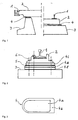
- Fig. 1 shows the railroad track according to the invention in two variants indicated for the respective vehicle type.
- a halfway for a Transrapid maglev is shown.
- the rails 1 are shown summarized in the representation of the known individual functional levels.
- the rail support structure 2 carries the rails 1 at their Kragplattenenden. It can be shown in FIG. 6 and 7 z. B. be designed as a cross sleeper, perforated plate or dissolved plate construction.
- the rail support structure 2 is connected in a positionally correct manner to the support structure 3 via the compensation layer 4 according to the invention.
- the supporting structure 3 is made of concrete or another solid building material.
- a halfway of a slab track according to the invention is shown.
- the rail support structure 2 is formed according to FIGS. 4 and 5 as a continuous or substructured cross sleeper or as an individual support.
- the rails 1 are indirectly connected via rail support structure 2 and on the compensating layer 4 according to the invention in a positionally correct manner with the supporting structure 3.
- the support structure 3 consists of a known asphalt or Ort laterrag für.
- Fig. 2 shows schematically the embodiment of a single support point of a rail 1 on the support layer 3 of a slab track.
- the rail support structure 2 may be a known ribbed plate, the contact surface with the leveling layer 4i for a good mold bond z. B. may also have a fine waffle structure.
- the compensation layer 4 consists here of a stack of the compensation layers 4i, 4k, and 4l, wherein additionally a reinforcement intermediate layer 5 is arranged between the compensation layers 4i and 4k.
- the individual compensation layers 4i, 4k, and 4l can differ both in thickness and dimensions as well as in the material composition.
- the individual compensation layers are configured as prefabricated plates.
- the rail support structure 2 can be fixed with anchors 6 on the support structure 3 or biased against the surface of the support structure 3. Because of the shear composite effect the leveling layer 4 are no dowels to secure the lateral displacement resistance required.
- Fig. 3 shows an inventively designed compensating layer plate 4 in plan.
- the plate edges 4b may be enriched with the thermoplastic binder relative to the core portion 4a. This results in a better adhesion of individual compensation layers in a stack with each other in the edge regions 4b or a correspondingly better local adhesion to the rail support structures 2, the support structure 3 or the reinforcement layers 5. If the edge regions 4b have a higher plastic stability, stress peaks at the component edges are easier degraded or the durability of extending beyond the components areas of the compensation layers is improved. Likewise, the drainage or sealing properties of the leveling layer can be controlled thereby. Because of the low volume requirement of the thermoplastic binder according to the invention, high-quality plastic can be used for this as a whole.
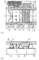
- the rails 1 are arranged on rail support structures 2 in the form of sleepers and individual supports.
- the rail support structures 2 are leveled and leveled over compensation layers 4 on the support structure 3 of the track and elastically secured in position over the composite effect of the compensation layer.
- intermediate elements 7 are superimposed in the threshold compartments on the rail support structures 2 with wedging action.
- the intermediate element 7 is supported as a vault pressure plate at four points of the rail support structures and stiffens them out as a disk.
- the rail support structure is loaded with the weight of the intermediate element.
- intermediate element holes are shown arranged for attachment with anchors 6 or biasing against the support structure 3 or for receiving or Versetzwerk with engagement tools.
- the curved underside of the intermediate elements ensures unimpeded outflow of surface water.
- the open in this variant end faces of the intermediate elements 7 can be closed with a known gravel 9 constructive and permeable to water.
- the intermediate elements 7 can be made of aggregated concrete for sound absorption.
- the intermediate element 7 is permeable to sound and rain water.
- an enclosed space is created between the components, into which sound is conducted and absorbed.
- the room will automatically fill up with organic material over time, which serves to further absorb sound.
- the space can be advantageous already in the production of the track with fiber tangle, z. B. straw mats, are filled.
- the room can instead be automatically rinsed with rainwater or artificially cleaned in an analogous manner.
- the top of the intermediate element 7 is structured according to the principle known lattice barriers for cattle, so that wild and ungulates are prevented from crossing the track. Nevertheless, the thus configured intermediate element 7 can be traveled on rubber-tired vehicles.
- To the sides of the driveway toward the effect picture is complemented by appropriate design of the finished elements 10.
- composite layers 8 are arranged, which are similar in materials, construction or composite action of the compensating layer 4.
- the rails 1 are arranged on rail support structures 2 in the form of cantilevers.
- the rail support structures 2 are leveled and leveled over compensation layers 4 on the support structure 3 of the track and elastically connected to each other via the composite effect of the compensation layer 4.
- intermediate elements 7 are shown arranged in the joints of the rail support structures 2 with wedging action.
- the rail support structures 2 are configured as isotropically rigid steel or prestressed concrete slab structures or anisotropically rigid steel / plastic / concrete composite structures.
- the choice consists of different design variants of the rail support structures 2.
- Quarrying similar constructions require slightly higher investment and installation costs, but have advantages in temperature expansion behavior or repair effort.
- perforated plate constructions as rail support structure 2 can also be advantageous.
- Air permeable panel constructions also improve the vibration behavior of the support structure from aerodynamic pressure / suction vibration excitation. Dissolved plate constructions or trusses of rigid sleepers with reduced compressive stiffness in the longitudinal direction of travel are probably a bit more expensive to produce, but have a more favorable tempering behavior with respect to durability.
- Between rail support structures 2 and wedge-like intermediate elements 7 are to compensate for forced voltages, z. B.
- the intermediate elements are prestressed against the supporting structure with a defined and lasting preloading force.
- the rail support structures 2 are accordingly biased more or less as thrust washers. This results in a consistently shear stiff transverse stiffening of the track construction for a better durability and securing the overall structure.
Landscapes
- Engineering & Computer Science (AREA)
- Architecture (AREA)
- Civil Engineering (AREA)
- Structural Engineering (AREA)
- Mechanical Engineering (AREA)
- Machines For Laying And Maintaining Railways (AREA)
- Railway Tracks (AREA)
Applications Claiming Priority (1)
| Application Number | Priority Date | Filing Date | Title |
|---|---|---|---|
| DE200410037170 DE102004037170B4 (de) | 2004-07-30 | 2004-07-30 | Verfahren zur Herstellung eines Schienenfahrwegs |
Publications (1)
| Publication Number | Publication Date |
|---|---|
| EP1621670A2 true EP1621670A2 (fr) | 2006-02-01 |
Family
ID=35170163
Family Applications (1)
| Application Number | Title | Priority Date | Filing Date |
|---|---|---|---|
| EP05016058A Withdrawn EP1621670A2 (fr) | 2004-07-30 | 2005-07-23 | Procédé de construction d'une voie ferrée et voie ferrée |
Country Status (2)
| Country | Link |
|---|---|
| EP (1) | EP1621670A2 (fr) |
| DE (1) | DE102004037170B4 (fr) |
Cited By (4)
| Publication number | Priority date | Publication date | Assignee | Title |
|---|---|---|---|---|
| DE102010053116A1 (de) | 2010-12-01 | 2012-06-06 | Thomas Marks | Partikel-Anordnung |
| CN107858872A (zh) * | 2017-12-25 | 2018-03-30 | 洛阳明创矿山冶金设备有限公司 | 一种可实现自动预紧的地铁导轨结构 |
| CN113152175A (zh) * | 2021-04-25 | 2021-07-23 | 中铁四院集团工程建设有限责任公司 | 一种板式无砟轨道的修复装置及其修复方法 |
| CN115859615A (zh) * | 2022-11-30 | 2023-03-28 | 中铁第四勘察设计院集团有限公司 | 基于矩法的荷载抗力分项系数直接计算方法、介质及设备 |
Families Citing this family (3)
| Publication number | Priority date | Publication date | Assignee | Title |
|---|---|---|---|---|
| DE102011108093B4 (de) * | 2011-07-19 | 2020-03-05 | Siemag Tecberg Gmbh | Fertigteilfahrbahn für Schrägförderanlage für Bergbautrucks |
| DE202017000831U1 (de) | 2017-02-15 | 2017-03-03 | Thomas Marks | Brücken-Verstärkung |
| DE202017001705U1 (de) | 2017-03-30 | 2017-04-20 | Thomas Marks | Verbundfuge |
Citations (2)
| Publication number | Priority date | Publication date | Assignee | Title |
|---|---|---|---|---|
| DE19808867A1 (de) | 1998-03-03 | 1999-09-09 | Ihle | Verfahren und Herstellung einer stabilen, tragfähigen, drainagefähigen oder dichten und schallabsorbierenden Festen-Fahrbahn aus einem dauerelastischen Kunststoffbeton für schienengebunde Fahrzeuge aller Art |
| DE10209873A1 (de) | 2002-03-06 | 2003-09-25 | Thomas Marks | Werkstoff |
Family Cites Families (1)
| Publication number | Priority date | Publication date | Assignee | Title |
|---|---|---|---|---|
| DE3429413A1 (de) * | 1984-08-09 | 1986-02-20 | Alfred Kunz GmbH & Co, 8000 München | Hoehen- und seitenregulierbarer oberbau fuer schienenbahnen mit trennbarer verkleidung von schwellen auf einer fugenlosen platte |
-
2004
- 2004-07-30 DE DE200410037170 patent/DE102004037170B4/de not_active Expired - Fee Related
-
2005
- 2005-07-23 EP EP05016058A patent/EP1621670A2/fr not_active Withdrawn
Patent Citations (2)
| Publication number | Priority date | Publication date | Assignee | Title |
|---|---|---|---|---|
| DE19808867A1 (de) | 1998-03-03 | 1999-09-09 | Ihle | Verfahren und Herstellung einer stabilen, tragfähigen, drainagefähigen oder dichten und schallabsorbierenden Festen-Fahrbahn aus einem dauerelastischen Kunststoffbeton für schienengebunde Fahrzeuge aller Art |
| DE10209873A1 (de) | 2002-03-06 | 2003-09-25 | Thomas Marks | Werkstoff |
Cited By (4)
| Publication number | Priority date | Publication date | Assignee | Title |
|---|---|---|---|---|
| DE102010053116A1 (de) | 2010-12-01 | 2012-06-06 | Thomas Marks | Partikel-Anordnung |
| CN107858872A (zh) * | 2017-12-25 | 2018-03-30 | 洛阳明创矿山冶金设备有限公司 | 一种可实现自动预紧的地铁导轨结构 |
| CN113152175A (zh) * | 2021-04-25 | 2021-07-23 | 中铁四院集团工程建设有限责任公司 | 一种板式无砟轨道的修复装置及其修复方法 |
| CN115859615A (zh) * | 2022-11-30 | 2023-03-28 | 中铁第四勘察设计院集团有限公司 | 基于矩法的荷载抗力分项系数直接计算方法、介质及设备 |
Also Published As
| Publication number | Publication date |
|---|---|
| DE102004037170B4 (de) | 2006-12-21 |
| DE102004037170A1 (de) | 2006-03-23 |
Similar Documents
| Publication | Publication Date | Title |
|---|---|---|
| AT391499B (de) | Eisenbahnoberbau, insbesondere fuer schienenfahrzeuge mit sehr hohen fahrgeschwindigkeiten | |
| DE4442497A1 (de) | Schotterloses Oberbausystem für zumindest ein Eisenbahngleis | |
| EP0663470B1 (fr) | Procédé d'obtention d'une superstructure de voies ferrées | |
| DE102004037170B4 (de) | Verfahren zur Herstellung eines Schienenfahrwegs | |
| DE4411833A1 (de) | Schallgedämpftes Straßenbahngleis | |
| EP0637645B1 (fr) | Voie rigide pour circulation sur rails | |
| DE4430769C2 (de) | Eisenbahnoberbau mit einem auf einer durchgehenden Tragplatte aus Stahlbeton aufgelagerten Gleisrost | |
| DE3429413A1 (de) | Hoehen- und seitenregulierbarer oberbau fuer schienenbahnen mit trennbarer verkleidung von schwellen auf einer fugenlosen platte | |
| DE4007710A1 (de) | Verfahren zum herstellen eines eisenbahnoberbaus im tunnel | |
| WO2009036990A1 (fr) | Dispositifs de superstructure ferroviaire | |
| DE102007028978B4 (de) | Gleiskörper für Schienenfahrzeuge | |
| EP0698143B1 (fr) | Superstructure stable pour voie de chemin de fer | |
| EP1216326B1 (fr) | Procede pour construire une voie insonorisee | |
| EP1486611B1 (fr) | Procédé de construction d'une voie permanente et une voie permanente | |
| DE19625249C2 (de) | Lagestabiler Gleiskörper aus Betonfertigteilen sowie Verwendung von Betonfertigteilen für diesen Gleiskörper | |
| DE10310754B4 (de) | Verfahren zur Herstellung einer festen Schienenfahrbahn; Feste Schienenfahrbahn | |
| DE102006055307A1 (de) | Schwellenbefestigung | |
| AT500876A1 (de) | Verfahren zum herstellen einer festen fahrbahn für schienenfahrzeuge | |
| DE4316664C2 (de) | Lagestabiler Eisenbahnoberbau | |
| EP1483450B1 (fr) | Procede de fabrication d'une voie ferree fixe et voie ferree fixe | |
| EP0724667A1 (fr) | Superstructure sans ballast a traverses en beton | |
| DE4133905A1 (de) | Spannbeton-verbundplatten nach der mehrschichtentheorie fuer den eisenbahnoberbau | |
| EP4473160A1 (fr) | Ensemble voie, procédé de production dudit ensemble voie et procédé de rénovation dudit ensemble voie | |
| AT405421B (de) | Verfahren zur herstellung eines oberbaues für gleise | |
| DE2354958A1 (de) | Verfahren zum herstellen eines schotterlosen oberbaues eines gleises und tragelement hierfuer |
Legal Events
| Date | Code | Title | Description |
|---|---|---|---|
| PUAI | Public reference made under article 153(3) epc to a published international application that has entered the european phase |
Free format text: ORIGINAL CODE: 0009012 |
|
| AK | Designated contracting states |
Kind code of ref document: A2 Designated state(s): AT BE BG CH CY CZ DE DK EE ES FI FR GB GR HU IE IS IT LI LT LU LV MC NL PL PT RO SE SI SK TR |
|
| AX | Request for extension of the european patent |
Extension state: AL BA HR MK YU |
|
| STAA | Information on the status of an ep patent application or granted ep patent |
Free format text: STATUS: THE APPLICATION HAS BEEN WITHDRAWN |
|
| 18W | Application withdrawn |
Effective date: 20060725 |