EP1621697A2 - Traggestellrahmen für Bekleidungselemente - Google Patents
Traggestellrahmen für Bekleidungselemente Download PDFInfo
- Publication number
- EP1621697A2 EP1621697A2 EP05105784A EP05105784A EP1621697A2 EP 1621697 A2 EP1621697 A2 EP 1621697A2 EP 05105784 A EP05105784 A EP 05105784A EP 05105784 A EP05105784 A EP 05105784A EP 1621697 A2 EP1621697 A2 EP 1621697A2
- Authority
- EP
- European Patent Office
- Prior art keywords
- supporting frame
- rapid clamping
- warp
- clamping elements
- elements
- Prior art date
- Legal status (The legal status is an assumption and is not a legal conclusion. Google has not performed a legal analysis and makes no representation as to the accuracy of the status listed.)
- Withdrawn
Links
Images


Classifications
-
- E—FIXED CONSTRUCTIONS
- E04—BUILDING
- E04F—FINISHING WORK ON BUILDINGS, e.g. STAIRS, FLOORS
- E04F13/00—Coverings or linings, e.g. for walls or ceilings
- E04F13/07—Coverings or linings, e.g. for walls or ceilings composed of covering or lining elements; Sub-structures therefor; Fastening means therefor
- E04F13/08—Coverings or linings, e.g. for walls or ceilings composed of covering or lining elements; Sub-structures therefor; Fastening means therefor composed of a plurality of similar covering or lining elements
- E04F13/0801—Separate fastening elements
- E04F13/0803—Separate fastening elements with load-supporting elongated furring elements between wall and covering elements
- E04F13/081—Separate fastening elements with load-supporting elongated furring elements between wall and covering elements with additional fastening elements between furring elements and covering elements
- E04F13/0814—Separate fastening elements with load-supporting elongated furring elements between wall and covering elements with additional fastening elements between furring elements and covering elements fixed by means of clamping action
-
- E—FIXED CONSTRUCTIONS
- E04—BUILDING
- E04F—FINISHING WORK ON BUILDINGS, e.g. STAIRS, FLOORS
- E04F13/00—Coverings or linings, e.g. for walls or ceilings
- E04F13/07—Coverings or linings, e.g. for walls or ceilings composed of covering or lining elements; Sub-structures therefor; Fastening means therefor
- E04F13/08—Coverings or linings, e.g. for walls or ceilings composed of covering or lining elements; Sub-structures therefor; Fastening means therefor composed of a plurality of similar covering or lining elements
- E04F13/0801—Separate fastening elements
- E04F13/0803—Separate fastening elements with load-supporting elongated furring elements between wall and covering elements
- E04F13/0805—Separate fastening elements with load-supporting elongated furring elements between wall and covering elements with additional fastening elements between furring elements and the wall
-
- E—FIXED CONSTRUCTIONS
- E04—BUILDING
- E04F—FINISHING WORK ON BUILDINGS, e.g. STAIRS, FLOORS
- E04F13/00—Coverings or linings, e.g. for walls or ceilings
- E04F13/07—Coverings or linings, e.g. for walls or ceilings composed of covering or lining elements; Sub-structures therefor; Fastening means therefor
- E04F13/08—Coverings or linings, e.g. for walls or ceilings composed of covering or lining elements; Sub-structures therefor; Fastening means therefor composed of a plurality of similar covering or lining elements
- E04F13/0801—Separate fastening elements
- E04F13/0803—Separate fastening elements with load-supporting elongated furring elements between wall and covering elements
- E04F13/081—Separate fastening elements with load-supporting elongated furring elements between wall and covering elements with additional fastening elements between furring elements and covering elements
- E04F13/0812—Separate fastening elements with load-supporting elongated furring elements between wall and covering elements with additional fastening elements between furring elements and covering elements fixed by means of spring action
-
- E—FIXED CONSTRUCTIONS
- E04—BUILDING
- E04F—FINISHING WORK ON BUILDINGS, e.g. STAIRS, FLOORS
- E04F13/00—Coverings or linings, e.g. for walls or ceilings
- E04F13/07—Coverings or linings, e.g. for walls or ceilings composed of covering or lining elements; Sub-structures therefor; Fastening means therefor
- E04F13/08—Coverings or linings, e.g. for walls or ceilings composed of covering or lining elements; Sub-structures therefor; Fastening means therefor composed of a plurality of similar covering or lining elements
- E04F13/0801—Separate fastening elements
- E04F13/0803—Separate fastening elements with load-supporting elongated furring elements between wall and covering elements
- E04F13/081—Separate fastening elements with load-supporting elongated furring elements between wall and covering elements with additional fastening elements between furring elements and covering elements
- E04F13/0821—Separate fastening elements with load-supporting elongated furring elements between wall and covering elements with additional fastening elements between furring elements and covering elements the additional fastening elements located in-between two adjacent covering elements
- E04F13/0826—Separate fastening elements with load-supporting elongated furring elements between wall and covering elements with additional fastening elements between furring elements and covering elements the additional fastening elements located in-between two adjacent covering elements engaging side grooves running along the whole length of the covering elements
Definitions
- the present invention concerns a supporting frame for covering elements of the modular type, such as bricks, panels, plates, tiles or suchlike, used in the building trade in order to cover surfaces of structures such as for example walls, pillars or columns.
- the invention is particularly indicated for making ventilated walls made of bricks and for this reason, in the following description, we shall refer specifically to this application, although this is not to be considered limitative.
- One purpose of the present invention is to achieve a supporting frame for covering elements, advantageously but not exclusively for bricks, which is simple and practical to use, and which allows to create covering structures quickly and with limited costs.
- Another purpose of the invention is to achieve a supporting frame for covering elements that is extremely versatile and therefore usable for various applications.
- the Applicant has devised, tested and embodied the present invention to overcome the shortcomings of the state of the art and to obtain these and other purposes and advantages.
- the supporting frame for covering elements comprises at least a first warp profile, advantageously an upright, provided with rapid clamping elements able to cooperate with mating grooves provided on the covering elements, in order to clamp the covering elements through interference, advantageously at least partly elastic, onto the first warp profile.
- the rapid clamping elements are aligned along the first warp profile with an interaxis substantially equivalent to one of the two positioning interaxes, for example the vertical interaxis, of the covering elements.
- a plurality of first warp profiles are present, each one provided with relative rapid clamping elements, disposed with respect to each other with an interaxis substantially equivalent to the other positioning interaxis, for example the horizontal interaxis, of the covering elements.
- the first warp profiles area also associated with second warp profiles, orthogonal thereto, attached to a bearing structure, for example a wall.
- the rapid clamping elements are disposed at the front of the first warp profiles and comprise fin means, advantageously at least partly elastic, having at least a part able to be inserted with interference into the grooves of the covering elements in order to clamp the latter.
- the rapid clamping elements are able to be selectively associated with the first warp profiles, and each of them comprises two fin means, opposite each other, able to cooperate with mating grooves of respective covering elements.
- each rapid clamping element comprises four fin means, disposed radially at 90° from each other, each of which is able to cooperate with a mating corner groove of a relative covering element.
- each rapid clamping element is able to selectively assume at least a first position, wherein the relative fin means are disposed outside the grooves of the covering elements, and a second position, rotated by 90° with respect to the first, wherein at least a part of the fin means is inserted into the relative grooves.
- each rapid clamping element comprises in a single piece at least a central part, connected with the fin means, and a retaining arm, advantageously at least partly elastic, able to be inserted into a mating aperture of the first warp profile, in order to move behind or inside the latter and, in cooperation with the central part, to be constrained thereon when the rapid clamping element is moved from the first to the second position.
- the rapid clamping elements are made integrally on the first warp profiles and each of them comprises at least a pair of fin means, opposite each other, able to cooperate with relative grooves of the same covering element.
- the fin means are L-shaped and at least some of them have V-shaped or hook-shaped ends.
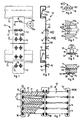
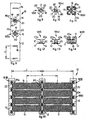
- the number 10 denotes generally a supporting frame according to the invention used to make structures with covering elements, in this case consisting of bricks 11.
- the frame 10 is advantageously made of metal and comprises a plurality of uprights, or vertical warp profiles, 12, each of which is attached between two cross-pieces, or horizontal warp profiles 13, able to be associated, in contact or at a distance, with a bearing structure 14, for example a wall.
- the cross-piece 13 is for example attached to a bracket 27 able to keep it at a distance from the bearing structure 14 on which the bracket 27 itself is anchored; this solution is particularly indicated for making ventilated walls.
- the uprights 12 are disposed with an interaxis "i" substantially equivalent to the horizontal positioning interaxis "a" of the bricks 11 (fig. 15).
- the uprights 12 at the upper end, have a shaping 12a by means of which they are able to be constrained due to their coupling shape inside a hollow 13a made on the cross-pieces 13.
- Each upright 12 is also able to be attached, at least at the lower part, to the relative cross-piece 13 by means of rivets, nails, bolts or other attachment elements.
- each upright 12 has at the front a plurality of horizontal eyelets 15, aligned in twos and disposed on two parallel and symmetrical rows with respect to the longitudinal axis of the upright 12.
- the eyelets 15 are disposed in a position corresponding to the grooves between the bricks 11, and their vertical interaxis "b" is substantially equivalent to the interaxis of vertical positioning "c" between the bricks 11.
- Each eyelet 15, at the center, has two little semicircular recesses 15a (fig. 1) on the lower and upper edge.
- a clamping element 16 is associated, able to be rotated from a first position "I” in which it does not interfere with the bricks 11, to a second position "II” in which it interferes with two relative bricks 11, to determine the clamping thereof.
- each clamping element 16 in a single piece, has a central disk 17 associated at the rear with a retaining arm 18, of a length substantially equivalent to the length of the eyelet 15, and at the front with two L-shaped fins 20, opposite each other (figs. 3 and 5).
- the fins 20 are partly elastic and their end 20a is able to be inserted with interference into a mating groove 21 made longitudinally on the upper and lower end of the bricks 11.
- the retaining arm 18 is partly elastic too, and between it and the central disk 17 there are two little ridges 19, opposite each other, of a shape mating with the semicircular recesses 15a of the eyelet 15.
- the clamping element 16 In the first position "I", the clamping element 16 has the retaining arm 18 substantially aligned with the eyelet 15, and the ridges 19 and the fins 20 aligned horizontally.
- the bricks 11 are laid simply by positioning each brick 11 between two uprights 12, so that the brick 11 is disposed between four clamping elements 16, and then by rotating the latter by 90° to take them from the first position "I" to the second position "II".
- each clamping element 16 determines, on the one hand, the disposition of the retaining arm 18 orthogonal to the eyelet 15 and the insertion of the ridges 19 into the semicircular recesses 15a, with the clamping element 16 consequently being constrained on the upright 12; and on the other hand, the vertical positioning of the fins 20 and the insertion with interference of the relative ends 20a into the grooves 21 of the bricks 11, with the consequent clamping of the latter with respect to the uprights 12 (figs. 4 and 6).
- the rotation of the clamping element 16 occurs by means of a tool able to be inserted into a mating impression made, for example, on the central disk 17.
- the uprights 12 can be disposed with a halved interaxis "i", to allow the bricks 11 to be laid in staggered courses.
- the uprights 12 have a single row of eyelets 15 with which clamping elements 16 are associated, provided with four fins 20 disposed radially at 90° from each other and rotated by 45° with respect to the retaining arm 18.
- the bricks 11 are laid by disposing them between two uprights 12 and making the clamping elements 16 rotate from the first position "I" to the second position "II", so that each fin 20 is inserted in a groove 22 of a different brick 11; in this case however, in order to allow the positioning of the bricks 11, the clamping elements 16 are taken to an intermediate position "X", rotated by 45° with respect to the first position "I”, so that the fins 20 are disposed two vertical and two horizontal (figs. 10 and 13), so as not to interfere with the bricks 11.
- the uprights 12 have a substantially C-shaped section and, as in the embodiment shown in figs. 1 ⁇ 7, have the eyelets 15 aligned in twos and disposed on two parallel and symmetrical rows with respect to the longitudinal axis of the uprights 12.
- the eyelets 15 have semicircular recesses 15a with a bigger radius, so as to allow screws 28 to be inserted, by means of which the uprights 12 are attached to the cross-pieces 13.
- each eyelet 15 on the inner surface of the upright 12, there are also four little protrusions 33 disposed in twos, parallel and opposite with respect to the longitudinal axis of the eyelet 15 itself, the function of which will be explained hereafter.
- the clamping elements 16 comprise in a single piece a rod 29, cylindrical in shape, from one end of which two opposite fins 30 branch off; the clamping elements 16 also comprise, in a single piece, a central plate 31 and a retaining arm 32, having substantially the same shape as that of the eyelet 15.
- the fins 30, which are substantially orthogonal to the rod 29, are separated from each other by a slit 34 and each of them has at the end a thin appendix 30a, advantageously some tens of a millimeter thick.
- the fins 30 are able to be inserted with interference into grooves 21 made longitudinally on the upper side and on the lower side of the bricks 11.
- the retaining arm 32 is able to be inserted into the eyelet 15, to move inside the upright 12, while the central plate 31, on the contrary, is of such a size that it cannot pass through the eyelet 15.
- each of them is disposed between two uprights 12, so as to be between four clamping elements 16 disposed in the first position "I", with the retaining arm 32 inserted into the eyelet 15 and the fins 30 aligned horizontally.
- each clamping element 16 is rotated by 90° so as to assume the second position "II", so that the retaining arm 32 is disposed orthogonal to the eyelet 15, with its ends first surmounting a respective protrusion 33 and then being disposed between the two pairs of protrusions 33, remaining constrained there (fig. 29).
- the fins 30 are disposed in vertical alignment, that is, substantially orthogonal to the respective eyelets 15, inserting themselves with interference into the grooves 21, so as to determine the clamping of the bricks 11 on the uprights 12 (figs. 26 and 28).
- the appendixes 30a are able to deform, on the one hand in order to increase the interference that determines the clamping of the bricks 11, and on the other hand in order to compensate possible differences in height between the grooves 21, or other imperfections of the bricks 11.
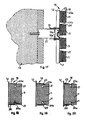
- the clamping elements 16 consist of pairs of partly elastic fins, respectively upper 23 and lower 24, made integrally on the upright 12.
- the fins 23 and 24 are aligned in twos and are disposed on two parallel and symmetrical rows with respect to the longitudinal axis of the upright 12.
- the fins 23 and 24 are also disposed in correspondence with the grooves between the bricks 11 and the distance between the upper fin 23 and the lower fin 24 of the same clamping element 16 is slightly more than the height of a brick 11.
- the upper fin 23 and the lower fin 24 of the same clamping element 16 are disposed facing each other and have the relative ends 23a and 24a facing respectively downwards and upwards; the ends 23a and 24a are able to be inserted with interference into mating grooves 21, longitudinal and through, made respectively on the upper and lower sides of the bricks 11.
- the fins 23 and 24 are both L-shaped with the relative ends 23a and 24a substantially vertical.
- the upper fin 23 on the contrary has a V-shaped end 23a, while in the embodiment in fig. 18, the same end 23a is shaped like a hook and is bent back towards the upright 12.
- the fins 23 and 24 both have the ends 23a and 24a shaped like a hook, in one case (fig. 19), and V-shaped in the other case (fig. 20).
- the fins 23 and 24 both have the ends 23a and 24a wedge-shaped, with a vertical segment and an inclined segment; the ends 23a and 24a are able to be inserted into grooves 21 with a mating section made on the bricks 11.
- the fins 23 and 24 are not made in a single piece with the upright 12, but are added thereon; to be more exact, a plurality of holes 25 are made on the upright 12, with a constant interaxis, in correspondence with each of which a shaped profile 26 is able to be attached, defining the upper fin 23 of a clamping element 16 and the lower fin 24 of the clamping element 16 immediately above.
- the bricks 11 are laid simply by disposing them between two uprights 12 and then thrusting them against the fins 23 and 24, so that the elastic deformation of the latter allows the relative ends 23a and 24a to be inserted with interference into the grooves 21.
- the bricks 11 are laid by means of lateral insertion.
Landscapes
- Engineering & Computer Science (AREA)
- Architecture (AREA)
- Civil Engineering (AREA)
- Structural Engineering (AREA)
- Finishing Walls (AREA)
Applications Claiming Priority (1)
| Application Number | Priority Date | Filing Date | Title |
|---|---|---|---|
| ITUD20040153 ITUD20040153A1 (it) | 2004-07-27 | 2004-07-27 | Telaio di supporto per elementi di rivestimento |
Publications (2)
| Publication Number | Publication Date |
|---|---|
| EP1621697A2 true EP1621697A2 (de) | 2006-02-01 |
| EP1621697A3 EP1621697A3 (de) | 2006-05-24 |
Family
ID=35033559
Family Applications (1)
| Application Number | Title | Priority Date | Filing Date |
|---|---|---|---|
| EP05105784A Withdrawn EP1621697A3 (de) | 2004-07-27 | 2005-06-29 | Traggestellrahmen für Bekleidungselemente |
Country Status (2)
| Country | Link |
|---|---|
| EP (1) | EP1621697A3 (de) |
| IT (1) | ITUD20040153A1 (de) |
Cited By (6)
| Publication number | Priority date | Publication date | Assignee | Title |
|---|---|---|---|---|
| WO2008000747A1 (en) * | 2006-06-28 | 2008-01-03 | Avantgarde Srl | Supporting frame for covering elements and clamping element used in the supporting frame |
| FR2941727A1 (fr) * | 2009-02-03 | 2010-08-06 | Grimmeisen Holzland Gmbh | Element de facade |
| EP2278090A1 (de) * | 2009-07-21 | 2011-01-26 | Galimberti S.r.l. | Befestigungssystem für eine oder mehrere Wandplatten, insbesondere zum Abdecken externer Gebäudewände und zugehöriges Verfahren zum Befestigen der Wandplatten |
| EP2299026A3 (de) * | 2009-09-07 | 2013-01-02 | Paolo Oliviero | Fassadenpaneel zur Befestigung von Mauerwerk |
| CN103133464A (zh) * | 2011-11-22 | 2013-06-05 | 三星爱宝乐园 | 用于木材的固定设备和具有该设备的板面设施 |
| CN107905476A (zh) * | 2017-10-27 | 2018-04-13 | 上海市建筑装饰工程集团有限公司 | 适用于高层加气块墙的格栅装饰面施工方法 |
Family Cites Families (6)
| Publication number | Priority date | Publication date | Assignee | Title |
|---|---|---|---|---|
| US2088625A (en) * | 1935-12-13 | 1937-08-03 | David A Wailace | Building brick |
| GB1125123A (en) * | 1965-09-01 | 1968-08-28 | Jules Scott Zibell | Improved building system for attaching panels to structural supports |
| JPH04323457A (ja) * | 1990-08-07 | 1992-11-12 | Kajima Corp | タイル支持具、タイル貼り壁構造及びタイル貼り帳壁 |
| DE4200124A1 (de) * | 1992-01-04 | 1993-07-15 | Herbert Heinemann | Befestigungsvorrichtung fuer eine gebaeudewandverkleidung |
| NL9500419A (nl) * | 1995-03-03 | 1996-10-01 | Anton Tapper | Samenstel omvattende een paneel en een profiel, alsmede veerelement, paneel, profiel en vormstrip geschikt voor toepassing in een dergelijk samenstel. |
| FR2843414B1 (fr) * | 2002-08-12 | 2005-02-11 | Christian Jean Crepin | Dispositif d'assemblage amovible d'elements plats constituant une surface plane |
-
2004
- 2004-07-27 IT ITUD20040153 patent/ITUD20040153A1/it unknown
-
2005
- 2005-06-29 EP EP05105784A patent/EP1621697A3/de not_active Withdrawn
Cited By (8)
| Publication number | Priority date | Publication date | Assignee | Title |
|---|---|---|---|---|
| WO2008000747A1 (en) * | 2006-06-28 | 2008-01-03 | Avantgarde Srl | Supporting frame for covering elements and clamping element used in the supporting frame |
| FR2941727A1 (fr) * | 2009-02-03 | 2010-08-06 | Grimmeisen Holzland Gmbh | Element de facade |
| EP2278090A1 (de) * | 2009-07-21 | 2011-01-26 | Galimberti S.r.l. | Befestigungssystem für eine oder mehrere Wandplatten, insbesondere zum Abdecken externer Gebäudewände und zugehöriges Verfahren zum Befestigen der Wandplatten |
| EP2299026A3 (de) * | 2009-09-07 | 2013-01-02 | Paolo Oliviero | Fassadenpaneel zur Befestigung von Mauerwerk |
| CN103133464A (zh) * | 2011-11-22 | 2013-06-05 | 三星爱宝乐园 | 用于木材的固定设备和具有该设备的板面设施 |
| CN103133464B (zh) * | 2011-11-22 | 2016-03-30 | 第一毛织株式会社 | 用于木材的固定设备和具有该设备的板面设施 |
| CN107905476A (zh) * | 2017-10-27 | 2018-04-13 | 上海市建筑装饰工程集团有限公司 | 适用于高层加气块墙的格栅装饰面施工方法 |
| CN107905476B (zh) * | 2017-10-27 | 2019-11-15 | 上海市建筑装饰工程集团有限公司 | 适用于高层加气块墙的格栅装饰面施工方法 |
Also Published As
| Publication number | Publication date |
|---|---|
| EP1621697A3 (de) | 2006-05-24 |
| ITUD20040153A1 (it) | 2004-10-27 |
Similar Documents
| Publication | Publication Date | Title |
|---|---|---|
| US6568138B1 (en) | Framing system and related framing section assembly | |
| US20180135309A1 (en) | Panel veneer systems | |
| US20100205873A1 (en) | Self centering shaft wall system | |
| US20040065035A1 (en) | Brick veneer holding plates | |
| US3248836A (en) | External wall panel and wall formed therefrom | |
| EP1621697A2 (de) | Traggestellrahmen für Bekleidungselemente | |
| WO2007086083A1 (en) | Supporting frame for covering elements | |
| US6843034B2 (en) | Masonry block locking device | |
| KR102189496B1 (ko) | 벽체 배수판 설치용 조립식 프레임 시스템 | |
| US3774366A (en) | Box beam structures and connections for beam-supported structures | |
| US12421730B2 (en) | Attachment clip for building surface panels and building surface panel system | |
| RU2609503C1 (ru) | Система облицовки фасада металлическими кассетами | |
| EP2864558B1 (de) | Belüftungseinheiten | |
| US3664073A (en) | Building panel construction and securement means therefor | |
| CN111411728B (zh) | 一种吊顶的边安装组件 | |
| IE832979L (en) | Structural system for partitioning a room | |
| EP3635191B1 (de) | Bausystem für wandverkleidung | |
| JP4099809B2 (ja) | レンガ壁およびレンガ壁施工方法 | |
| EP1681403A2 (de) | Ausrüstung zur Konstruktion von modular ausgestatteten Wänden | |
| JPH0240665Y2 (de) | ||
| KR200278531Y1 (ko) | 건축물 마감판재를 지지하기 위한 골조틀의 결합구조 | |
| EP2309073A1 (de) | Wandverkleidungsanordnung und Wandverkleidungselement | |
| CA1115923A (en) | Panel joint assembly for double wall panels | |
| KR102910269B1 (ko) | 프레임 조립체 및 이의 시공 방법 | |
| KR200450108Y1 (ko) | 건축물 외벽 마감재용 연결구 |
Legal Events
| Date | Code | Title | Description |
|---|---|---|---|
| PUAI | Public reference made under article 153(3) epc to a published international application that has entered the european phase |
Free format text: ORIGINAL CODE: 0009012 |
|
| AK | Designated contracting states |
Kind code of ref document: A2 Designated state(s): AT BE BG CH CY CZ DE DK EE ES FI FR GB GR HU IE IS IT LI LT LU MC NL PL PT RO SE SI SK TR |
|
| AX | Request for extension of the european patent |
Extension state: AL BA HR LV MK YU |
|
| PUAL | Search report despatched |
Free format text: ORIGINAL CODE: 0009013 |
|
| AK | Designated contracting states |
Kind code of ref document: A3 Designated state(s): AT BE BG CH CY CZ DE DK EE ES FI FR GB GR HU IE IS IT LI LT LU MC NL PL PT RO SE SI SK TR |
|
| AX | Request for extension of the european patent |
Extension state: AL BA HR LV MK YU |
|
| AKX | Designation fees paid | ||
| REG | Reference to a national code |
Ref country code: DE Ref legal event code: 8566 |
|
| STAA | Information on the status of an ep patent application or granted ep patent |
Free format text: STATUS: THE APPLICATION IS DEEMED TO BE WITHDRAWN |
|
| 18D | Application deemed to be withdrawn |
Effective date: 20061125 |