EP1621817B1 - Nachbrenner mit gesicherter Zündung - Google Patents
Nachbrenner mit gesicherter Zündung Download PDFInfo
- Publication number
- EP1621817B1 EP1621817B1 EP05291480A EP05291480A EP1621817B1 EP 1621817 B1 EP1621817 B1 EP 1621817B1 EP 05291480 A EP05291480 A EP 05291480A EP 05291480 A EP05291480 A EP 05291480A EP 1621817 B1 EP1621817 B1 EP 1621817B1
- Authority
- EP
- European Patent Office
- Prior art keywords
- burner
- injector
- fuel
- spark plug
- chamber
- Prior art date
- Legal status (The legal status is an assumption and is not a legal conclusion. Google has not performed a legal analysis and makes no representation as to the accuracy of the status listed.)
- Expired - Lifetime
Links
Images


Classifications
-
- F—MECHANICAL ENGINEERING; LIGHTING; HEATING; WEAPONS; BLASTING
- F23—COMBUSTION APPARATUS; COMBUSTION PROCESSES
- F23R—GENERATING COMBUSTION PRODUCTS OF HIGH PRESSURE OR HIGH VELOCITY, e.g. GAS-TURBINE COMBUSTION CHAMBERS
- F23R3/00—Continuous combustion chambers using liquid or gaseous fuel
- F23R3/02—Continuous combustion chambers using liquid or gaseous fuel characterised by the air-flow or gas-flow configuration
- F23R3/16—Continuous combustion chambers using liquid or gaseous fuel characterised by the air-flow or gas-flow configuration with devices inside the flame tube or the combustion chamber to influence the air or gas flow
- F23R3/18—Flame stabilising means, e.g. flame holders for after-burners of jet-propulsion plants
- F23R3/20—Flame stabilising means, e.g. flame holders for after-burners of jet-propulsion plants incorporating fuel injection means
Definitions
- the invention relates to a turbojet afterburner chamber and relates more particularly to an improvement of the ignition system of said afterburner.
- Post-combustion is used in military aircraft to rapidly increase the engine thrust and consequently the speed of the aircraft when flight conditions require it.
- the US Patent 5,396,761 discloses a post combustion chamber comprising a plurality of radially extending burners, one of which is equipped with an ignition system comprising a candle associated with an injector.
- the latter has orifices oriented away from the spark plug so that ignition is not ensured for all operating conditions of the reactor.
- the U.S. Patent 3,931,707 discloses a post-combustion chamber equipped with a burner ring which has a plurality of nozzles delivering fuel upstream of a ring of fixed vanes where the fuel mixes with air entering the ring by a slot downstream. A candle can ignite this fuel. However, there is nothing to control the vaporization of the fuel so that the mixture ignites under all flight conditions.
- the invention applies to an adjacent type of combustion chamber equipped with an annular burner and a spark plug capable of generating sparks for the ignition of the post combustion.
- the end of the candle is placed opposite a point of an annular fuel distribution ramp.
- the pressure and the fuel injection temperature in the ramp may be too high. weak or too variable. We can not directly intervene on the injection pressure in the annular ramp. Therefore, the ignition is uncertain and sometimes the post combustion does not trigger, without necessarily incriminating the operation of the candle.
- the invention solves this problem.
- the invention relates to a post-combustion chamber comprising an annular ramp for injecting the afterburner fuel and a spark plug mounted in the vicinity of said annular ramp, characterized in that an ignition injector is installed next to said spark plug and is connected to specific fuel supply means capable of delivering said fuel under a controlled pressure independent of the supply conditions of said annular ramp.
- the specific ignition injector fed by a fuel source different from that which feeds the burner and spraying fuel for a few seconds opposite the spark plug ensures the ignition of the afterburner.
- the specific power source of the ignition injector can be stopped until the next post-combustion trigger.
- the spark plug emits several sparks per second until ignition.
- the ignition period lasts a few seconds, for example between three and ten seconds.
- the injector is provided with a special nozzle which vaporizes the jet in very fine particles smaller than fifty microns.
- annular ramp is mounted in a burner ring
- said injector protrudes inside this ring at the back of the candle.
- a post-combustion chamber there is a classically distinguished internal hot primary stream where the gases delivered by the turbine flow and a secondary colder external stream separated from the primary stream by a ferrule.
- the injector and the spark plug are housed in a protective sleeve attached to an outer casing, commonly called a heat sink and opening into said burner ring.
- This protective sheath isolates the ignition system from said hot primary stream.
- the protective sheath advantageously comprises ventilation orifices communicating with the cold secondary flow. In this way, cold air circulates continuously inside the protective sleeve to keep the ignition system at an acceptable temperature.
- FIG. 1 to 4 there is shown a portion of the post-combustion chamber 11 of a turbojet engine 12 located downstream of the turbine (not shown) in the X'X axis thereof.
- the casing 14 of the post combustion chamber is connected by bolting to the end of a diffuser housing 16, also called a heating cover.
- An inner exhaust casing 18 is connected to an ejection cone 19 extending axially in the central part of said diffuser housing 16.
- a ferrule 20 which separates and channels the primary gas flow F 1 , indoor and secondary F 2 , outdoor.
- the primary flow F 1 of the gases from the turbine is at high temperature while the secondary flow F 2 from the compressor is relatively low temperature and allows to cool the structural elements of the post-combustion chamber.
- An inner liner 22 carried by the casing 14 defines the afterburner chamber downstream of a combustion system 25 essentially comprising a burner ring 26 and radial arms 27 extending from the burner ring towards the inside of the combustion chamber. the post-combustion chamber to the vicinity of the axis X'X thereof.
- the jacket 22 and the casing 14 define between them an annular cooling channel 28 extending all around the post-combustion chamber 11.
- the radial arms 27 are nine in number, regularly distributed circumferentially.
- Each arm has a V-shaped section whose wings diverge rearwardly and form two rectilinear sprayed fuel ejection ramps, constituting a so-called "flame-holder" structure.
- Each arm has in its outermost radial part an aerodynamically profiled element 30, through which it is connected to the casing 16. This element makes it possible to channel the secondary flow, in particular towards the annular cooling channel 28.
- These arms, intended to maintain the combustion in the center of the post-combustion chamber are of conventional design and are not concerned by the invention; they will not be described in more detail.
- the burner ring 26 of the afterburner system 25 is substantially of revolution about the axis X'X; it is carried by the elements 30.
- the burner ring opens rearwardly between the arms 27 and the inner liner 22.
- the rearward opening portion has a V-shaped section in a radial plane passing through the X'X axis.
- the burner ring 26 houses an annular fuel injection ramp 34 comprising an internal spraying tube 36, pierced with a plurality of very small diameter holes 35 and extending inside a protective tube 38 (FIG. pierced with holes of relatively large diameter regularly spaced circumferentially) forming anti-radiation shield for the thermal protection of the spray tube.
- the holes 35 of the spraying tube 36 coincide with the holes of the protective tube 38.
- the annular ramp 34 extends over substantially the entire circumference of the burner ring 26. In known manner, said burner ring is supplied with fuel by a conduit 40 connected to a main fuel supply source, not shown.
- a spark plug 42 is conventionally installed in the vicinity of the annular spray bar 34. It is slidably engaged in a sleeve 43 which has a flange 44 which is itself sliding in the nozzle. defined space between the outer wall of the burner ring 26 and a frame 45 welded thereto, around the hole through which the end of the candle enters said burner ring.
- an ignition injector 48 is installed opposite said spark plug 42 and is connected to specific fuel supply means capable of delivering said fuel under a controlled pressure independent of the supply conditions of said annular ramp.
- Injector 48 is itself specific because it is fed by a special fuel source (not shown) by a particular conduit 49.
- the spray nozzle of the injector 48 which protrudes into the burner ring, is slidably engaged in a sleeve 47 which has a flange 50 which itself slides in the space defined between the wall of the burner ring ( at the front thereof) and a frame 51 welded thereto around the hole through which said tip enters the burner ring.
- the specific injector 48 is here of the aeromechanical type. It is equipped with a fine fuel spraying nozzle, capable of delivering particles smaller than fifty microns. The injector is placed so that the end of the spark plug 42 (where the spark occurs) is in the spray cone 54 of the injector.
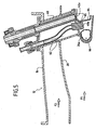
- the figure 5 illustrates a variant in which the burner ring 26a is disposed in the hot primary flow F 1 (which depends on the general design of the reactor).
- the structural elements similar to those previously described bear the same reference numerals. They will not be described again. Due to the location of the burner ring, it is intended to protect the ignition system (specific injector 48a and candle 42a) in a protective sleeve 60 fixed to the housing 16 and communicating with the burner ring. The sheath 60 thus crosses the secondary flow F2.
- the protective sheath has ventilation orifices 62 communicating with the cold secondary flow.
- the inside of the sheath is constantly traversed by a stream of cold air.
- a heat shield 64 is also placed between the injector and the end of the spark plug. It has a passage 65 facing the spray orifice of the specific injector.
- An annular ventilation box 66 is installed inside the burner ring 26a.
- the fuel is injected into the burner ring 26 and the arms 27 and, simultaneously but with different pressure conditions, a small amount of additional fuel is injected through the injector 48.
- the spark produced by the spark plug 42 is created in the spray cone of the injector, which causes the ignition of the fuel injected by the specific injector, then that of the fuel delivered along the burner ring and arms.
Landscapes
- Engineering & Computer Science (AREA)
- Chemical & Material Sciences (AREA)
- Combustion & Propulsion (AREA)
- Mechanical Engineering (AREA)
- General Engineering & Computer Science (AREA)
- Pressure-Spray And Ultrasonic-Wave- Spray Burners (AREA)
- Exhaust Gas After Treatment (AREA)
Claims (6)
- Nachbrennkammer (11) mit einer Ringleitung (34) zum Einspritzen des Nachbrennkraftstoffs sowie mit einer in der Nähe der Ringleitung angebrachten Zündkerze (42), dadurch gekennzeichnet, daß ein Zündungsinjektor (48) gegenüber der Kerze angebracht und mit speziellen Kraftstoffversorgungsmitteln (49) verbunden ist, welche geeignet sind, den Kraftstoff unter einem von den Versorgungsbedingungen der Ringleitung unabhängigen kontrollierten Druck zu liefern.
- Nachbrennkammer nach Anspruch 1, dadurch gekennzeichnet, daß der Injektor (48) mit einer Düse zur Feinzerstäubung des Kraftstoffs ausgestattet ist.
- Nachbrennkammer nach einem der vorhergehenden Ansprüche, bei der die Ringleitung in einem Brennerring (26) angebracht ist, dadurch gekennzeichnet, daß der Injektor (48) in dem Brennerring (26) angebracht ist und in der Nähe der Kerze in diesen mündet.
- Nachbrennkammer nach einem der Ansprüche 2 oder 3, von der Art, bei welcher der Brennerring in dem heißen Primärstrom (F1) der Brennkammer angeordnet ist, dadurch gekennzeichnet, daß der Injektor (48a) und die Kerze (42a) in einem Schutzmantel (60) untergebracht sind, der an einem Außengehäuse befestigt ist und in den Brennerring (26a) mündet.
- Nachbrennkammer nach Anspruch 4, dadurch gekennzeichnet, daß der Schutzmantel Lüftungsöffnungen (62) aufweist, die mit dem kalten Sekundärstrom der Nachbrennkammer in Verbindung stehen.
- Turbostrahltriebwerk, dadurch gekennzeichnet, daß es eine Nachbrennkammer nach einem der vorhergehenden Ansprüche aufweist.
Applications Claiming Priority (1)
| Application Number | Priority Date | Filing Date | Title |
|---|---|---|---|
| FR0407909A FR2873168B1 (fr) | 2004-07-16 | 2004-07-16 | Turboreacteur comprenant une chambre de post-combustion a allumage securise |
Publications (2)
| Publication Number | Publication Date |
|---|---|
| EP1621817A1 EP1621817A1 (de) | 2006-02-01 |
| EP1621817B1 true EP1621817B1 (de) | 2009-01-28 |
Family
ID=34947700
Family Applications (1)
| Application Number | Title | Priority Date | Filing Date |
|---|---|---|---|
| EP05291480A Expired - Lifetime EP1621817B1 (de) | 2004-07-16 | 2005-07-08 | Nachbrenner mit gesicherter Zündung |
Country Status (6)
| Country | Link |
|---|---|
| US (1) | US20060292504A1 (de) |
| EP (1) | EP1621817B1 (de) |
| CA (1) | CA2511875A1 (de) |
| DE (1) | DE602005012560D1 (de) |
| FR (1) | FR2873168B1 (de) |
| RU (1) | RU2005122513A (de) |
Families Citing this family (8)
| Publication number | Priority date | Publication date | Assignee | Title |
|---|---|---|---|---|
| FR2900460B1 (fr) * | 2006-04-28 | 2012-10-05 | Snecma | Systeme annulaire de post-combustion d'une turbomachine |
| FR2942640B1 (fr) | 2009-03-02 | 2011-05-06 | Snecma | Chambre de post-combustion pour turbomachine |
| US8893502B2 (en) * | 2011-10-14 | 2014-11-25 | United Technologies Corporation | Augmentor spray bar with tip support bushing |
| CN105716106B (zh) * | 2014-12-04 | 2019-07-05 | 中国航空工业集团公司沈阳发动机设计研究所 | 一种在试验器上实现热射流点火的装置 |
| FR3039220B1 (fr) * | 2015-07-24 | 2017-08-11 | Snecma | Dipositif de postcombustion pour turboreacteur |
| FR3097298B1 (fr) | 2019-06-12 | 2021-06-04 | Safran Aircraft Engines | Bougie intégrée au bras accroche-flamme |
| FR3107570B1 (fr) * | 2020-02-26 | 2022-02-04 | Safran Aircraft Engines | Brûleur de postcombustion a integration optimisée |
| EP4276357B1 (de) | 2022-05-11 | 2025-11-19 | Rolls-Royce plc | Verbrennungssystem |
Family Cites Families (12)
| Publication number | Priority date | Publication date | Assignee | Title |
|---|---|---|---|---|
| GB842197A (en) * | 1958-07-23 | 1960-07-20 | Gen Electric | Improvements in afterburner combustion equipment of a gas turbine jet propulsion engine |
| DE1133185B (de) * | 1959-04-21 | 1962-07-12 | Snecma | Verbrennungseinrichtung an Rueckstosstrieb-werken, insbesondere zur Nachverbrennung |
| US3016706A (en) * | 1960-09-09 | 1962-01-16 | United Aircraft Corp | Jet ignition system |
| GB938553A (en) * | 1961-05-09 | 1963-10-02 | Rolls Royce | Reheat combustion apparatus for a gas turbine engine |
| DE1240746B (de) * | 1964-08-08 | 1967-05-18 | Heinkel Ag Ernst | Strahlduese, insbesondere fuer den Nachbrenner eines Flugzeugtriebwerks, mit mechanisch gesteuerter Strahlablenkung |
| US3765178A (en) * | 1972-09-08 | 1973-10-16 | Gen Electric | Afterburner flameholder |
| US3931707A (en) * | 1975-01-08 | 1976-01-13 | General Electric Company | Augmentor flameholding apparatus |
| US4170109A (en) * | 1977-11-09 | 1979-10-09 | United Technologies Corporation | Thrust augmentor having swirled flows for combustion stabilization |
| US4315401A (en) * | 1979-11-30 | 1982-02-16 | United Technologies Corporation | Afterburner flameholder construction |
| US5396761A (en) | 1994-04-25 | 1995-03-14 | General Electric Company | Gas turbine engine ignition flameholder with internal impingement cooling |
| FR2770284B1 (fr) * | 1997-10-23 | 1999-11-19 | Snecma | Accroche-flamme carbure et a refroidissement optimise |
| US7437876B2 (en) * | 2005-03-25 | 2008-10-21 | General Electric Company | Augmenter swirler pilot |
-
2004
- 2004-07-16 FR FR0407909A patent/FR2873168B1/fr not_active Expired - Fee Related
-
2005
- 2005-07-08 EP EP05291480A patent/EP1621817B1/de not_active Expired - Lifetime
- 2005-07-08 DE DE602005012560T patent/DE602005012560D1/de not_active Expired - Lifetime
- 2005-07-13 CA CA002511875A patent/CA2511875A1/fr not_active Abandoned
- 2005-07-15 RU RU2005122513/06A patent/RU2005122513A/ru not_active Application Discontinuation
- 2005-07-15 US US11/181,924 patent/US20060292504A1/en not_active Abandoned
Also Published As
| Publication number | Publication date |
|---|---|
| EP1621817A1 (de) | 2006-02-01 |
| FR2873168B1 (fr) | 2008-10-31 |
| DE602005012560D1 (de) | 2009-03-19 |
| RU2005122513A (ru) | 2007-01-20 |
| CA2511875A1 (fr) | 2006-01-16 |
| FR2873168A1 (fr) | 2006-01-20 |
| US20060292504A1 (en) | 2006-12-28 |
Similar Documents
| Publication | Publication Date | Title |
|---|---|---|
| EP2501996B1 (de) | Brennkammer mit ventilierter zündkerze | |
| EP1278012B1 (de) | Aeromechanisches Einspritzsystem mit Primärverwirbelungs- und Rückschlagvorrichtung | |
| FR2626043A1 (fr) | Dispositif de formation de turbulences-injecteur de carburant pour ensemble de combustion dans une turbine a gaz | |
| FR2931203A1 (fr) | Injecteur de carburant pour turbine a gaz et son procede de fabrication | |
| CA2646959A1 (fr) | Systeme d'injection d'un melange d'air et de carburant dans une chambre de combustion de turbomachine | |
| FR2921463A1 (fr) | Chambre de combustion d'une turbomachine | |
| EP3578884B1 (de) | Verbrennungskammer für eine turbomaschine | |
| FR2980554A1 (fr) | Chambre annulaire de combustion d'une turbomachine | |
| EP1621817B1 (de) | Nachbrenner mit gesicherter Zündung | |
| FR3122719A1 (fr) | Accroche-flammes pour postcombustion de turboréacteur comprenant des bras à bords de fuite dentelés | |
| EP1770333B1 (de) | Anti-Verkokungsinjektorarm | |
| FR2996286A1 (fr) | Dispositif d'injection pour une chambre de combustion de turbomachine | |
| FR3084446A1 (fr) | Chambre de combustion monobloc | |
| FR2942640A1 (fr) | Chambre de post-combustion pour turbomachine | |
| FR2943119A1 (fr) | Systemes d'injection de carburant dans une chambre de combustion de turbomachine | |
| EP4004443B1 (de) | Brennkammer mit sekundäreinspritzsystemen und verfahren zur kraftstoffversorgung | |
| FR3039220A1 (fr) | Dipositif de postcombustion pour turboreacteur | |
| FR3038363A1 (fr) | Chambre annulaire de combustion a diaphragme fixe, pour une turbine a gaz | |
| EP4179256B1 (de) | Ringbrennkammer für eine flugzeugturbomaschine | |
| EP4327023B1 (de) | Diffusionskegel für das heckteil eines strahltriebwerks mit einem flammenhalterring an der hinterkante | |
| FR3136016A1 (fr) | Anneau accroche-flammes pour postcombustion de turboreacteur comprenant un conduit pour chauffer un segment angulaire de l'anneau | |
| FR3121974A1 (fr) | Dispositif accroche-flammes pour postcombustion de turboréacteur comprenant des bras à trois branches | |
| FR3121959A1 (fr) | Dispositif d'injection de carburant amélioré pour postcombustion de turboréacteur | |
| FR3071550A1 (fr) | Chambre annulaire de combustion | |
| FR3113302A1 (fr) | Chambre de combustion pour une turbomachine |
Legal Events
| Date | Code | Title | Description |
|---|---|---|---|
| PUAI | Public reference made under article 153(3) epc to a published international application that has entered the european phase |
Free format text: ORIGINAL CODE: 0009012 |
|
| 17P | Request for examination filed |
Effective date: 20050715 |
|
| AK | Designated contracting states |
Kind code of ref document: A1 Designated state(s): AT BE BG CH CY CZ DE DK EE ES FI FR GB GR HU IE IS IT LI LT LU LV MC NL PL PT RO SE SI SK TR |
|
| AX | Request for extension of the european patent |
Extension state: AL BA HR MK YU |
|
| RAP1 | Party data changed (applicant data changed or rights of an application transferred) |
Owner name: SNECMA |
|
| RIN1 | Information on inventor provided before grant (corrected) |
Inventor name: CHARPENEL, SABINE CONSTANCE MAUD Inventor name: ROCHE, JACQUES-A. Inventor name: BABOEUF, SEBASTIEN PIERRE LOUIS Inventor name: DURAND, DIDIER NOEL |
|
| 17Q | First examination report despatched |
Effective date: 20060831 |
|
| AKX | Designation fees paid |
Designated state(s): DE FR GB SE |
|
| GRAP | Despatch of communication of intention to grant a patent |
Free format text: ORIGINAL CODE: EPIDOSNIGR1 |
|
| GRAS | Grant fee paid |
Free format text: ORIGINAL CODE: EPIDOSNIGR3 |
|
| GRAA | (expected) grant |
Free format text: ORIGINAL CODE: 0009210 |
|
| AK | Designated contracting states |
Kind code of ref document: B1 Designated state(s): DE FR GB SE |
|
| REG | Reference to a national code |
Ref country code: GB Ref legal event code: FG4D Free format text: NOT ENGLISH |
|
| REF | Corresponds to: |
Ref document number: 602005012560 Country of ref document: DE Date of ref document: 20090319 Kind code of ref document: P |
|
| REG | Reference to a national code |
Ref country code: SE Ref legal event code: TRGR |
|
| PLBE | No opposition filed within time limit |
Free format text: ORIGINAL CODE: 0009261 |
|
| STAA | Information on the status of an ep patent application or granted ep patent |
Free format text: STATUS: NO OPPOSITION FILED WITHIN TIME LIMIT |
|
| 26N | No opposition filed |
Effective date: 20091029 |
|
| REG | Reference to a national code |
Ref country code: FR Ref legal event code: PLFP Year of fee payment: 12 |
|
| REG | Reference to a national code |
Ref country code: FR Ref legal event code: PLFP Year of fee payment: 13 |
|
| REG | Reference to a national code |
Ref country code: FR Ref legal event code: CD Owner name: SAFRAN AIRCRAFT ENGINES Effective date: 20170719 |
|
| REG | Reference to a national code |
Ref country code: FR Ref legal event code: PLFP Year of fee payment: 14 |
|
| PGFP | Annual fee paid to national office [announced via postgrant information from national office to epo] |
Ref country code: GB Payment date: 20240620 Year of fee payment: 20 |
|
| PGFP | Annual fee paid to national office [announced via postgrant information from national office to epo] |
Ref country code: FR Payment date: 20240619 Year of fee payment: 20 |
|
| PGFP | Annual fee paid to national office [announced via postgrant information from national office to epo] |
Ref country code: SE Payment date: 20240619 Year of fee payment: 20 |
|
| PGFP | Annual fee paid to national office [announced via postgrant information from national office to epo] |
Ref country code: DE Payment date: 20240619 Year of fee payment: 20 |
|
| REG | Reference to a national code |
Ref country code: DE Ref legal event code: R071 Ref document number: 602005012560 Country of ref document: DE |
|
| REG | Reference to a national code |
Ref country code: GB Ref legal event code: PE20 Expiry date: 20250707 |
|
| REG | Reference to a national code |
Ref country code: SE Ref legal event code: EUG |