EP1621820A1 - Integrierte Armatur zur Wärmeübertragung zwischen einem Hochtemperatur- und einem Niedertemperatur-Kreislauf in einem Wasserheizungssystem - Google Patents
Integrierte Armatur zur Wärmeübertragung zwischen einem Hochtemperatur- und einem Niedertemperatur-Kreislauf in einem Wasserheizungssystem Download PDFInfo
- Publication number
- EP1621820A1 EP1621820A1 EP05254605A EP05254605A EP1621820A1 EP 1621820 A1 EP1621820 A1 EP 1621820A1 EP 05254605 A EP05254605 A EP 05254605A EP 05254605 A EP05254605 A EP 05254605A EP 1621820 A1 EP1621820 A1 EP 1621820A1
- Authority
- EP
- European Patent Office
- Prior art keywords
- temperature
- fixture
- loop
- casting
- temperature loop
- Prior art date
- Legal status (The legal status is an assumption and is not a legal conclusion. Google has not performed a legal analysis and makes no representation as to the accuracy of the status listed.)
- Granted
Links
Images



Classifications
-
- F—MECHANICAL ENGINEERING; LIGHTING; HEATING; WEAPONS; BLASTING
- F04—POSITIVE - DISPLACEMENT MACHINES FOR LIQUIDS; PUMPS FOR LIQUIDS OR ELASTIC FLUIDS
- F04D—NON-POSITIVE-DISPLACEMENT PUMPS
- F04D29/00—Details, component parts, or accessories
- F04D29/40—Casings; Connections of working fluid
- F04D29/42—Casings; Connections of working fluid for radial or helico-centrifugal pumps
- F04D29/426—Casings; Connections of working fluid for radial or helico-centrifugal pumps especially adapted for liquid pumps
-
- F—MECHANICAL ENGINEERING; LIGHTING; HEATING; WEAPONS; BLASTING
- F04—POSITIVE - DISPLACEMENT MACHINES FOR LIQUIDS; PUMPS FOR LIQUIDS OR ELASTIC FLUIDS
- F04D—NON-POSITIVE-DISPLACEMENT PUMPS
- F04D13/00—Pumping installations or systems
- F04D13/12—Combinations of two or more pumps
- F04D13/14—Combinations of two or more pumps the pumps being all of centrifugal type
-
- F—MECHANICAL ENGINEERING; LIGHTING; HEATING; WEAPONS; BLASTING
- F24—HEATING; RANGES; VENTILATING
- F24D—DOMESTIC- OR SPACE-HEATING SYSTEMS, e.g. CENTRAL HEATING SYSTEMS; DOMESTIC HOT-WATER SUPPLY SYSTEMS; ELEMENTS OR COMPONENTS THEREFOR
- F24D3/00—Hot-water central heating systems
- F24D3/08—Hot-water central heating systems in combination with systems for domestic hot-water supply
-
- F—MECHANICAL ENGINEERING; LIGHTING; HEATING; WEAPONS; BLASTING
- F24—HEATING; RANGES; VENTILATING
- F24D—DOMESTIC- OR SPACE-HEATING SYSTEMS, e.g. CENTRAL HEATING SYSTEMS; DOMESTIC HOT-WATER SUPPLY SYSTEMS; ELEMENTS OR COMPONENTS THEREFOR
- F24D3/00—Hot-water central heating systems
- F24D3/10—Feed-line arrangements, e.g. providing for heat-accumulator tanks, expansion tanks ; Hydraulic components of a central heating system
- F24D3/1058—Feed-line arrangements, e.g. providing for heat-accumulator tanks, expansion tanks ; Hydraulic components of a central heating system disposition of pipes and pipe connections
- F24D3/1066—Distributors for heating liquids
-
- F—MECHANICAL ENGINEERING; LIGHTING; HEATING; WEAPONS; BLASTING
- F24—HEATING; RANGES; VENTILATING
- F24D—DOMESTIC- OR SPACE-HEATING SYSTEMS, e.g. CENTRAL HEATING SYSTEMS; DOMESTIC HOT-WATER SUPPLY SYSTEMS; ELEMENTS OR COMPONENTS THEREFOR
- F24D3/00—Hot-water central heating systems
- F24D3/12—Tube and panel arrangements for ceiling, wall, or underfloor heating
-
- Y—GENERAL TAGGING OF NEW TECHNOLOGICAL DEVELOPMENTS; GENERAL TAGGING OF CROSS-SECTIONAL TECHNOLOGIES SPANNING OVER SEVERAL SECTIONS OF THE IPC; TECHNICAL SUBJECTS COVERED BY FORMER USPC CROSS-REFERENCE ART COLLECTIONS [XRACs] AND DIGESTS
- Y02—TECHNOLOGIES OR APPLICATIONS FOR MITIGATION OR ADAPTATION AGAINST CLIMATE CHANGE
- Y02B—CLIMATE CHANGE MITIGATION TECHNOLOGIES RELATED TO BUILDINGS, e.g. HOUSING, HOUSE APPLIANCES OR RELATED END-USER APPLICATIONS
- Y02B30/00—Energy efficient heating, ventilation or air conditioning [HVAC]
Definitions
- This invention relates to hydronic radiant heating systems, and in some aspects to hydronic heating.
- a radiant heating system is composed of tubing embedded in flooring, walls, or ceilings of the area to be heated. Heated water is pumped through this tubing to raise the temperature of the surface (thermal mass). Heat energy radiating from the thermal mass heats the objects in the room As the method of heat transfer in these systems is primarily radiant, lower temperature water is required to heat the thermal mass than is typically needed for convection type systems (e.g., finned tube baseboard heating). In systems where the heat source is not solely dedicated to supplying heated water to the radiant loop, a means of tempering the higher temperature water from a heating unit loop, or other type of heating unit loop, is necessary to maintain lower temperature requirements in the radiant loop. An injection loop can perform this tempering by supplying water from the heating unit loop to the radiant loop.
- the amount ofheated water injected into the radiant loop can be set using a manually adjusted mixing valve, or using a variable speed injecaon pump.
- the heating unit is a domestic hot water heater, and water from the heating unit loop may be used as potable water, the water in the heating unit loop may be isolated from the water in the radiant loop and heat may be transferred from the heating unit loop to the radiant loop via a heat exchanger.
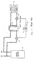
- FIG. 1 shows a prior art hydronic system of the-type described above.
- the water in the two loops flows through two sides of a heat exchanger 14, an the directions indicated by the arrows in FIG 1, causing heat to transfer from the water entering the heating unit loop from the outlet of the water heater, to the water returning from the radiant loop.
- a thermostat 19 and associated electrical circuit controls a relay 20 that switches the two circulators on.
- This type of heat-exchanger-based water circulating system may also be used with other types of heat sources, e.g., a boiler, in applications in which it is desirable to separate the water in the two loops.
- a boiler e.g., a heat source that is used in the radiant loop, e.g., for an outdoar heated driveway or walkway, it may be desirable to isolate the water in the heating unit loop from the antifreeze solution even if the heat source is a boiler or other source that does not supply potable water.
- the circulator pumps are typically of the wet rotor circulator type.
- the pump impeller is received in a mating cavity known as a volute.
- the volute is surrounded by a flange to which the pump is attached.
- the invention features an integrated fixture for transferring heat from a higher-temperature loop to a lower-temperature loop,(.e.g., in radiant heating, from a heating unit loop to a radiant loop).
- the fixture provides a beat exchanger for transferring heat from the higber-temperature loop to the lower-temperature loop.
- the fixture comprises a casting,in which are formed higher-temperature supply and return ports, lower-temperature supply and return ports, a higher-temperature pump volute, and a lower-temperature pump volute.
- Liquid from the higher-temperature loop enters the fixture through the higher-temperature supply port, passes through one side of the heat exchanger, transferring heat to liquid circulating through the other side of the heat exchanger in the lower-temperature loop, and leaves the fixture through the higher-temperature return port.
- Liquid circulating in the lower-temperature loop enters the fixture through the lower-temperature return port, receives the heat from the higher temperature liquid, and leaves the fixture through the lower-temperature supply port.
- the invention simplifies instaLlation by integrating into one integrated fixture all four ports and both circulator pumps.
- the integrated fixture may be for a radiant heating system
- the higher-temperature loop may be a boiler loop or a domestic water heater loop
- the lower-temperature loop may be a radiant loop.
- the heat exchanger may be replaceable.
- a check valve may be provided in the path followed by liquid traveling from the heating unit supply port to the higher-temperature circulator pump, or in the path from the higher-temperature circulator pump to the heating unit return port.
- the radiant loop supply and return ports may be located so that the ports are spaced apart by a distance approximating the spacing of the radiant supply and return ports on radiant heat flow manifolds.
- the integrated fixture may comprise a plurality of separate castings joined together, e.g., by close-fitting, mating connections sealed with O-ring type seals.
- the first and second portions of the casting may be in separate castings.
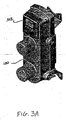
- FIGS. 2-5 show one implementation of the invention.
- An integrated fixture 21 formed of bronze, plastic, or other material consistent with the applied system conditions
- Each of the ports has a threaded connection (but any of the known alternative plumbing connections, e.g., sweated, could be substituted).
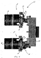
- a heating unit circulator pump 30 is bolted to flange 34 of the first casting 100.
- the impeller 35 of the circulator pump 30 is received in a volute 36, formed in the first casting. Liquid flows into the circulator pump 30 at inlet 38, and exits at an outlet (not shown) at the periphery of the volute.
- An internal passage within the casting connects the pump outlet to the heating unit return port 24.
- a radiant loop circulator pump 40 is bolted to flange 42 of the second casting 102.
- the impeller 43 of the radiant loop pump is received in volute 44, formed in the second casting. Liquid flows into the radiant loop pump at an inlet (not shown), and exits at an outlet 46 at the periphery of the volute.
- An internal passage within the casting connects the pump outlet to the radiant loop supply port 26.
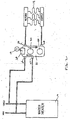
- Water from the heating unit loop i.e., water that has been heated by water heater 10, enters the first casting through the heating unit supply port 22, passes through one side of heat exchanger 60, and then leaves the first casting through the heating unit return port 24.
- water circulating in the radiant loop enters the second casting through the radiant loop return port 28, passes through the other side of the heat exchanger, and leaves the second casting through the radiant loop supply port 26.
- the water in the two loops flows through the heat exchanger in opposite directions, as indicated by the arrows in FIG 2.
- heat is transferred across a separating wall (not shown) of the heat exchanger to the liquid returning from the radiant loop at return port 28, heating this liquid prior to its delivery to the radiant heating coils.
- the water in the heating unit loop maybe used as potable water, and the liquid in the radiant loop can contain additives or contaminants that would be unacceptable in potable water, for example antifreeze (glycols).
- antifreeze glycols
- An electrical circuit including control circuitry for controlling the two circulator pumps is installed on the integrated fixture, and responds to input from a thermostat 19 to control the two circulator pumps.
- the heat exchanger 60 is replaceable.
- the heat exchanger is bolted to the integrated fixture.
- a pair of sealing rings 106, 108 may be provided at each casting/heat exchanger interface to ensure a water-tight seal.
- the sealing rings are preferably arranged generally parallel to each other and spaced apart along the length of the interface, as shown in FIG 6.
- the spacing (pitch) between ihe radiant loop supply and return connections is preferably set to match the standard spacing for radiant supply and return manifolds (which supply multiple radiant loops).
- the integrated fixture is sized and configured to permit easy mounting of the fixture to a wall panel.
- the integrated fixture may include a housing 100 and an electronic system control panel 102.
- the electronic system controls can be mounted in any desired location, e.g., on the pumps, the integrated fixture, or the support panel.
- the integrated fixture may be comprised of a plurality of individual castings that have close-fitting, mating connections that are sealed by o-ring type seals.
- the integrated casting is formed of three elements that are bolted together: a heat exchanger 60 (e.g., a braised plate heat exchanger) and the two individual castings 100 and 102 discussed above.
- a heat exchanger 60 e.g., a braised plate heat exchanger
- bolts or other mechanical fasteners hold the plurality of individual castings together, as shown.
- the connections between the individual castings are not of the type used routinely for making connections between plumbing fittings in the field (e.g., sweat or threaded connections).
- the plurality of individual castings would be assembled at the factory and delivered to the customer as an assembled unit.
- heating unit in FIG 2, other types of heating units may be used, such as boilers.
- the integrated fixture could have other types of connections (e,g., sweated, union, barbed, and grooved).
- a replaccable flow-check device (not shown) may be installed in the heating unit supply port (the inlet from the heating unit loop).
- Either or both of the circulator pumps may be variable speed circulator pumps.
- Variable speed circulator pumps may be provided, for example, to provide enhanced control over the heat delivered by the heating system.
- the circulator pumps may be turned on and off in tandem or independently, depending on the requirements of a particular hydronic system.
Landscapes
- Engineering & Computer Science (AREA)
- Mechanical Engineering (AREA)
- General Engineering & Computer Science (AREA)
- Physics & Mathematics (AREA)
- Thermal Sciences (AREA)
- Chemical & Material Sciences (AREA)
- Combustion & Propulsion (AREA)
- Water Supply & Treatment (AREA)
- Steam Or Hot-Water Central Heating Systems (AREA)
- Structures Of Non-Positive Displacement Pumps (AREA)
- Heat-Pump Type And Storage Water Heaters (AREA)
- Central Heating Systems (AREA)
Applications Claiming Priority (1)
| Application Number | Priority Date | Filing Date | Title |
|---|---|---|---|
| US10/899,837 US7044398B2 (en) | 2004-07-26 | 2004-07-26 | Integrated fixture for transferring heat between higher and lower-temperature loops in a hydronic heating system |
Publications (2)
| Publication Number | Publication Date |
|---|---|
| EP1621820A1 true EP1621820A1 (de) | 2006-02-01 |
| EP1621820B1 EP1621820B1 (de) | 2012-10-17 |
Family
ID=35197856
Family Applications (1)
| Application Number | Title | Priority Date | Filing Date |
|---|---|---|---|
| EP05254605A Expired - Lifetime EP1621820B1 (de) | 2004-07-26 | 2005-07-25 | Integrierte Armatur zur Wärmeübertragung zwischen einem Hochtemperatur- und einem Niedertemperatur-Kreislauf in einem Wasserheizungssystem |
Country Status (5)
| Country | Link |
|---|---|
| US (1) | US7044398B2 (de) |
| EP (1) | EP1621820B1 (de) |
| CN (1) | CN1746570B (de) |
| RU (1) | RU2391607C2 (de) |
| UA (1) | UA89942C2 (de) |
Cited By (4)
| Publication number | Priority date | Publication date | Assignee | Title |
|---|---|---|---|---|
| EP1777349A1 (de) * | 2005-10-18 | 2007-04-25 | Heatwork AS | Vorrichtung zum Auftauen eines Bodens |
| DE102007047667A1 (de) * | 2007-10-05 | 2009-04-09 | Watts Industries Deutschland Gmbh | Verfahren und Vorrichtung zum Verhindern der Kondensation von Luftfeuchtigkeit an kalten Soleleitungen |
| EP1840474A3 (de) * | 2006-03-29 | 2009-07-15 | Fafco Incorporated | Bausatz für Solarwasserheizsystem |
| RU2452897C2 (ru) * | 2010-09-07 | 2012-06-10 | Юрий Петрович Устименко | Способ подпитки отопительной системы горячей водой, предотвращающий возникновение гидроударов |
Families Citing this family (18)
| Publication number | Priority date | Publication date | Assignee | Title |
|---|---|---|---|---|
| US7048200B2 (en) * | 2003-06-27 | 2006-05-23 | Taco, Inc. | Integrated injection-pumping fixture for transferring heat between higher and lower-temperature loops in a hydronic heating system |
| US7507066B2 (en) * | 2006-03-27 | 2009-03-24 | Koenig Kevin J | Pump header body and modular manifold |
| US8202040B2 (en) * | 2006-03-27 | 2012-06-19 | Koenig Kevin J | Pump header and implementation thereof |
| US20080216821A1 (en) * | 2007-03-05 | 2008-09-11 | Taco, Inc. | Solar heating systems with integrated circulator control |
| US7708010B2 (en) * | 2007-03-05 | 2010-05-04 | Taco Inc. | Solar heating systems |
| FI20070868A7 (fi) * | 2007-11-15 | 2009-05-16 | Uponor Innovation Ab | Pinnan alaisen lämmityksen/jäähdytyksen säätäminen |
| CA2649941A1 (en) * | 2008-01-15 | 2009-07-15 | Michael Marchildon | Mixing and pumping system for use with installed hydronic radiant floor heating systems and the like |
| JP5174950B2 (ja) * | 2009-03-26 | 2013-04-03 | 三菱電機株式会社 | 温度調整装置、流体供給システム、暖房システム、温度調整装置の取付方法及び流体供給方法 |
| GB201120687D0 (en) * | 2011-12-01 | 2012-01-11 | Enviromax Ltd | Method of improving the efficiency of a central heating system |
| WO2014014236A1 (ko) * | 2012-07-20 | 2014-01-23 | Shin Yoon Min | 온수 보일러와 난방 배관용 파이프 및 그 설치구조 |
| GB201402193D0 (en) | 2014-02-07 | 2014-03-26 | Laberge Sylvain | Baseboard for use in preheating water |
| US20160230767A1 (en) * | 2015-02-11 | 2016-08-11 | Steve Thompson | High efficiency hydronic circulator with sensors |
| BR112017023320A2 (en) * | 2015-04-27 | 2018-08-14 | Virtual Fluid Monitoring Services LLC | fluid analysis and monitoring systems, apparatus and methods |
| EP3112549A1 (de) * | 2015-07-01 | 2017-01-04 | KEOKI Company SA | Baupaneel zur erstellung von heizwänden und/oder kühlwänden von gebäuden |
| CA3193016C (en) * | 2018-01-22 | 2023-10-10 | Energy Wall Llc | System, components, and methods for air, heat, and humidity exchanger |
| CZ308007B6 (cs) | 2018-05-14 | 2019-10-16 | ÄŚeskĂ© vysokĂ© uÄŤenĂ technickĂ© v Praze | Zařízení pro řízení výkonu tepelného výměníku v jednopotrubní otopné síti |
| CN108679703A (zh) * | 2018-05-24 | 2018-10-19 | 合肥顺昌分布式能源综合应用技术有限公司 | 一种基于分布式供热的同区域供热系统 |
| US11143418B2 (en) | 2019-04-03 | 2021-10-12 | The Marley Company Llc | System and method for controlling a variable-speed appliance circulator |
Citations (5)
| Publication number | Priority date | Publication date | Assignee | Title |
|---|---|---|---|---|
| GB1222509A (en) * | 1967-04-24 | 1971-02-17 | Thermega Ltd | Improvements in and relating to fluid heated heating devices |
| US4019681A (en) * | 1975-02-19 | 1977-04-26 | Josef Dumser | Thermal distributing unit |
| EP0507104A1 (de) * | 1991-03-19 | 1992-10-07 | WILO GmbH | Vorrichtung zur Versorgung einer Fussbodenheizung |
| EP0810406A2 (de) * | 1996-05-30 | 1997-12-03 | Tifell Electro Solar Sintens, S.A. | Einteiliger Sammler-Verteiler für Heizungs-und Heisswasseranlagen |
| DE10008913A1 (de) * | 1999-03-13 | 2000-09-14 | Ecotec Consulting Gmbh | Fußbodenheizverteiler mit Wärmetauscher |
Family Cites Families (7)
| Publication number | Priority date | Publication date | Assignee | Title |
|---|---|---|---|---|
| GB122509A (en) | 1918-02-08 | 1919-01-30 | Frederick Wilfrid Scott Stokes | Improvements in or relating to Projectiles. |
| US2784945A (en) * | 1953-07-04 | 1957-03-12 | Fodor Nicholas | Heating and cooling system for a bungalow |
| DE2224242A1 (de) * | 1972-05-18 | 1973-11-29 | Ctc Gmbh | Anlage zur temperierung, insbesondere zur kuehlung von raeumen |
| US5643482A (en) * | 1996-01-16 | 1997-07-01 | Heat Timer Corporation | Snow melt control system |
| US6126081A (en) * | 1998-06-29 | 2000-10-03 | Calvin; Donald R. | Atmospheric liquid heater |
| RU2171435C1 (ru) * | 2000-02-16 | 2001-07-27 | Еськов-Сосковец Владимир Михайлович | Устройство для нагрева жидкости |
| RU2229626C1 (ru) * | 2002-11-28 | 2004-05-27 | Закрытое акционерное общество "Уралэлектро-К" | Насос моноблочный |
-
2004
- 2004-07-26 US US10/899,837 patent/US7044398B2/en not_active Expired - Lifetime
-
2005
- 2005-07-25 EP EP05254605A patent/EP1621820B1/de not_active Expired - Lifetime
- 2005-07-25 RU RU2005124058/06A patent/RU2391607C2/ru active
- 2005-07-25 CN CN2005100849508A patent/CN1746570B/zh not_active Expired - Lifetime
- 2005-07-25 UA UAA200507404A patent/UA89942C2/ru unknown
Patent Citations (5)
| Publication number | Priority date | Publication date | Assignee | Title |
|---|---|---|---|---|
| GB1222509A (en) * | 1967-04-24 | 1971-02-17 | Thermega Ltd | Improvements in and relating to fluid heated heating devices |
| US4019681A (en) * | 1975-02-19 | 1977-04-26 | Josef Dumser | Thermal distributing unit |
| EP0507104A1 (de) * | 1991-03-19 | 1992-10-07 | WILO GmbH | Vorrichtung zur Versorgung einer Fussbodenheizung |
| EP0810406A2 (de) * | 1996-05-30 | 1997-12-03 | Tifell Electro Solar Sintens, S.A. | Einteiliger Sammler-Verteiler für Heizungs-und Heisswasseranlagen |
| DE10008913A1 (de) * | 1999-03-13 | 2000-09-14 | Ecotec Consulting Gmbh | Fußbodenheizverteiler mit Wärmetauscher |
Cited By (4)
| Publication number | Priority date | Publication date | Assignee | Title |
|---|---|---|---|---|
| EP1777349A1 (de) * | 2005-10-18 | 2007-04-25 | Heatwork AS | Vorrichtung zum Auftauen eines Bodens |
| EP1840474A3 (de) * | 2006-03-29 | 2009-07-15 | Fafco Incorporated | Bausatz für Solarwasserheizsystem |
| DE102007047667A1 (de) * | 2007-10-05 | 2009-04-09 | Watts Industries Deutschland Gmbh | Verfahren und Vorrichtung zum Verhindern der Kondensation von Luftfeuchtigkeit an kalten Soleleitungen |
| RU2452897C2 (ru) * | 2010-09-07 | 2012-06-10 | Юрий Петрович Устименко | Способ подпитки отопительной системы горячей водой, предотвращающий возникновение гидроударов |
Also Published As
| Publication number | Publication date |
|---|---|
| US7044398B2 (en) | 2006-05-16 |
| RU2005124058A (ru) | 2007-01-27 |
| EP1621820B1 (de) | 2012-10-17 |
| CN1746570B (zh) | 2011-06-01 |
| US20060016903A1 (en) | 2006-01-26 |
| CN1746570A (zh) | 2006-03-15 |
| RU2391607C2 (ru) | 2010-06-10 |
| UA89942C2 (ru) | 2010-03-25 |
Similar Documents
| Publication | Publication Date | Title |
|---|---|---|
| EP1621820B1 (de) | Integrierte Armatur zur Wärmeübertragung zwischen einem Hochtemperatur- und einem Niedertemperatur-Kreislauf in einem Wasserheizungssystem | |
| US7708010B2 (en) | Solar heating systems | |
| US6345770B1 (en) | Modular manifold | |
| US5390660A (en) | Pre-wired and pre-plumbed module for use with an installed hydronic radiant floor heating system | |
| CN101371080A (zh) | 用来分配和调节来自热源和/或冷源的载热体的装置 | |
| US5950575A (en) | Hydronic manifold | |
| EP3171036B1 (de) | Flüssigkeitskühlungsstation | |
| US4314547A (en) | Solar hot water system with sub-loop hydronic heating | |
| US7048200B2 (en) | Integrated injection-pumping fixture for transferring heat between higher and lower-temperature loops in a hydronic heating system | |
| US20070235179A1 (en) | Building source heat pump | |
| US20080216821A1 (en) | Solar heating systems with integrated circulator control | |
| CN105705867A (zh) | 用于液压供热和/或冷却系统的液压分配器 | |
| US20090178717A1 (en) | Mixing and pumping system for use with installed hydronic radiant floor heating systems and the like | |
| US7661441B2 (en) | Multi-line fluid conduit modules | |
| US3254839A (en) | Unitary heating system | |
| EP2041496B1 (de) | Anordnung und verfahren zum ändern der temperatur eines ersten und eines zweiten fluids, die sich in getrennten behältern befinden | |
| EP3540324A1 (de) | System zur zirkulation eines hitzemediums | |
| KR19980018617A (ko) | 온수·위생수겸용설비용 수압식 어셈블리 | |
| EP0508245A1 (de) | Kombiniertes Heiz- und Kühlsystem | |
| WO2007139327A1 (en) | Electric boiler of direct connection type | |
| US7275698B2 (en) | Apparatus and method for installing a heating system in a building | |
| US12173932B2 (en) | Valve | |
| JP7097060B2 (ja) | ポンプユニットおよび給湯システム | |
| FI79890C (fi) | Elektrisk vaermare foer ett motorfordons avkylningssystem. | |
| WO1997017575A1 (en) | Liquid-circulation heating system and pump |
Legal Events
| Date | Code | Title | Description |
|---|---|---|---|
| PUAI | Public reference made under article 153(3) epc to a published international application that has entered the european phase |
Free format text: ORIGINAL CODE: 0009012 |
|
| 17P | Request for examination filed |
Effective date: 20050805 |
|
| AK | Designated contracting states |
Kind code of ref document: A1 Designated state(s): AT BE BG CH CY CZ DE DK EE ES FI FR GB GR HU IE IS IT LI LT LU LV MC NL PL PT RO SE SI SK TR |
|
| AX | Request for extension of the european patent |
Extension state: AL BA HR MK YU |
|
| AKX | Designation fees paid |
Designated state(s): AT BE BG CH CY CZ DE DK EE ES FI FR GB GR HU IE IS IT LI LT LU LV MC NL PL PT RO SE SI SK TR |
|
| GRAP | Despatch of communication of intention to grant a patent |
Free format text: ORIGINAL CODE: EPIDOSNIGR1 |
|
| GRAS | Grant fee paid |
Free format text: ORIGINAL CODE: EPIDOSNIGR3 |
|
| GRAA | (expected) grant |
Free format text: ORIGINAL CODE: 0009210 |
|
| AK | Designated contracting states |
Kind code of ref document: B1 Designated state(s): AT BE BG CH CY CZ DE DK EE ES FI FR GB GR HU IE IS IT LI LT LU LV MC NL PL PT RO SE SI SK TR |
|
| REG | Reference to a national code |
Ref country code: GB Ref legal event code: FG4D |
|
| REG | Reference to a national code |
Ref country code: CH Ref legal event code: EP Ref country code: CH Ref legal event code: NV Representative=s name: KIRKER & CIE S.A. |
|
| REG | Reference to a national code |
Ref country code: IE Ref legal event code: FG4D |
|
| REG | Reference to a national code |
Ref country code: AT Ref legal event code: REF Ref document number: 580094 Country of ref document: AT Kind code of ref document: T Effective date: 20121115 |
|
| REG | Reference to a national code |
Ref country code: DE Ref legal event code: R096 Ref document number: 602005036556 Country of ref document: DE Effective date: 20121213 |
|
| REG | Reference to a national code |
Ref country code: AT Ref legal event code: MK05 Ref document number: 580094 Country of ref document: AT Kind code of ref document: T Effective date: 20121017 |
|
| REG | Reference to a national code |
Ref country code: NL Ref legal event code: VDEP Effective date: 20121017 |
|
| REG | Reference to a national code |
Ref country code: LT Ref legal event code: MG4D |
|
| PG25 | Lapsed in a contracting state [announced via postgrant information from national office to epo] |
Ref country code: FI Free format text: LAPSE BECAUSE OF FAILURE TO SUBMIT A TRANSLATION OF THE DESCRIPTION OR TO PAY THE FEE WITHIN THE PRESCRIBED TIME-LIMIT Effective date: 20121017 Ref country code: LT Free format text: LAPSE BECAUSE OF FAILURE TO SUBMIT A TRANSLATION OF THE DESCRIPTION OR TO PAY THE FEE WITHIN THE PRESCRIBED TIME-LIMIT Effective date: 20121017 Ref country code: NL Free format text: LAPSE BECAUSE OF FAILURE TO SUBMIT A TRANSLATION OF THE DESCRIPTION OR TO PAY THE FEE WITHIN THE PRESCRIBED TIME-LIMIT Effective date: 20121017 Ref country code: IS Free format text: LAPSE BECAUSE OF FAILURE TO SUBMIT A TRANSLATION OF THE DESCRIPTION OR TO PAY THE FEE WITHIN THE PRESCRIBED TIME-LIMIT Effective date: 20130217 Ref country code: SE Free format text: LAPSE BECAUSE OF FAILURE TO SUBMIT A TRANSLATION OF THE DESCRIPTION OR TO PAY THE FEE WITHIN THE PRESCRIBED TIME-LIMIT Effective date: 20121017 Ref country code: ES Free format text: LAPSE BECAUSE OF FAILURE TO SUBMIT A TRANSLATION OF THE DESCRIPTION OR TO PAY THE FEE WITHIN THE PRESCRIBED TIME-LIMIT Effective date: 20130128 |
|
| PG25 | Lapsed in a contracting state [announced via postgrant information from national office to epo] |
Ref country code: GR Free format text: LAPSE BECAUSE OF FAILURE TO SUBMIT A TRANSLATION OF THE DESCRIPTION OR TO PAY THE FEE WITHIN THE PRESCRIBED TIME-LIMIT Effective date: 20130118 Ref country code: CY Free format text: LAPSE BECAUSE OF FAILURE TO SUBMIT A TRANSLATION OF THE DESCRIPTION OR TO PAY THE FEE WITHIN THE PRESCRIBED TIME-LIMIT Effective date: 20121017 Ref country code: SI Free format text: LAPSE BECAUSE OF FAILURE TO SUBMIT A TRANSLATION OF THE DESCRIPTION OR TO PAY THE FEE WITHIN THE PRESCRIBED TIME-LIMIT Effective date: 20121017 Ref country code: BE Free format text: LAPSE BECAUSE OF FAILURE TO SUBMIT A TRANSLATION OF THE DESCRIPTION OR TO PAY THE FEE WITHIN THE PRESCRIBED TIME-LIMIT Effective date: 20121017 Ref country code: PT Free format text: LAPSE BECAUSE OF FAILURE TO SUBMIT A TRANSLATION OF THE DESCRIPTION OR TO PAY THE FEE WITHIN THE PRESCRIBED TIME-LIMIT Effective date: 20130218 Ref country code: PL Free format text: LAPSE BECAUSE OF FAILURE TO SUBMIT A TRANSLATION OF THE DESCRIPTION OR TO PAY THE FEE WITHIN THE PRESCRIBED TIME-LIMIT Effective date: 20121017 Ref country code: LV Free format text: LAPSE BECAUSE OF FAILURE TO SUBMIT A TRANSLATION OF THE DESCRIPTION OR TO PAY THE FEE WITHIN THE PRESCRIBED TIME-LIMIT Effective date: 20121017 |
|
| PG25 | Lapsed in a contracting state [announced via postgrant information from national office to epo] |
Ref country code: AT Free format text: LAPSE BECAUSE OF FAILURE TO SUBMIT A TRANSLATION OF THE DESCRIPTION OR TO PAY THE FEE WITHIN THE PRESCRIBED TIME-LIMIT Effective date: 20121017 |
|
| PG25 | Lapsed in a contracting state [announced via postgrant information from national office to epo] |
Ref country code: DK Free format text: LAPSE BECAUSE OF FAILURE TO SUBMIT A TRANSLATION OF THE DESCRIPTION OR TO PAY THE FEE WITHIN THE PRESCRIBED TIME-LIMIT Effective date: 20121017 Ref country code: SK Free format text: LAPSE BECAUSE OF FAILURE TO SUBMIT A TRANSLATION OF THE DESCRIPTION OR TO PAY THE FEE WITHIN THE PRESCRIBED TIME-LIMIT Effective date: 20121017 Ref country code: CZ Free format text: LAPSE BECAUSE OF FAILURE TO SUBMIT A TRANSLATION OF THE DESCRIPTION OR TO PAY THE FEE WITHIN THE PRESCRIBED TIME-LIMIT Effective date: 20121017 Ref country code: BG Free format text: LAPSE BECAUSE OF FAILURE TO SUBMIT A TRANSLATION OF THE DESCRIPTION OR TO PAY THE FEE WITHIN THE PRESCRIBED TIME-LIMIT Effective date: 20130117 Ref country code: EE Free format text: LAPSE BECAUSE OF FAILURE TO SUBMIT A TRANSLATION OF THE DESCRIPTION OR TO PAY THE FEE WITHIN THE PRESCRIBED TIME-LIMIT Effective date: 20121017 |
|
| PLBE | No opposition filed within time limit |
Free format text: ORIGINAL CODE: 0009261 |
|
| STAA | Information on the status of an ep patent application or granted ep patent |
Free format text: STATUS: NO OPPOSITION FILED WITHIN TIME LIMIT |
|
| PG25 | Lapsed in a contracting state [announced via postgrant information from national office to epo] |
Ref country code: RO Free format text: LAPSE BECAUSE OF FAILURE TO SUBMIT A TRANSLATION OF THE DESCRIPTION OR TO PAY THE FEE WITHIN THE PRESCRIBED TIME-LIMIT Effective date: 20121017 |
|
| 26N | No opposition filed |
Effective date: 20130718 |
|
| REG | Reference to a national code |
Ref country code: DE Ref legal event code: R097 Ref document number: 602005036556 Country of ref document: DE Effective date: 20130718 |
|
| PG25 | Lapsed in a contracting state [announced via postgrant information from national office to epo] |
Ref country code: MC Free format text: LAPSE BECAUSE OF FAILURE TO SUBMIT A TRANSLATION OF THE DESCRIPTION OR TO PAY THE FEE WITHIN THE PRESCRIBED TIME-LIMIT Effective date: 20121017 |
|
| REG | Reference to a national code |
Ref country code: IE Ref legal event code: MM4A |
|
| REG | Reference to a national code |
Ref country code: FR Ref legal event code: ST Effective date: 20140331 |
|
| PG25 | Lapsed in a contracting state [announced via postgrant information from national office to epo] |
Ref country code: FR Free format text: LAPSE BECAUSE OF NON-PAYMENT OF DUE FEES Effective date: 20130731 |
|
| PG25 | Lapsed in a contracting state [announced via postgrant information from national office to epo] |
Ref country code: IE Free format text: LAPSE BECAUSE OF NON-PAYMENT OF DUE FEES Effective date: 20130725 |
|
| PG25 | Lapsed in a contracting state [announced via postgrant information from national office to epo] |
Ref country code: TR Free format text: LAPSE BECAUSE OF FAILURE TO SUBMIT A TRANSLATION OF THE DESCRIPTION OR TO PAY THE FEE WITHIN THE PRESCRIBED TIME-LIMIT Effective date: 20121017 |
|
| PG25 | Lapsed in a contracting state [announced via postgrant information from national office to epo] |
Ref country code: HU Free format text: LAPSE BECAUSE OF FAILURE TO SUBMIT A TRANSLATION OF THE DESCRIPTION OR TO PAY THE FEE WITHIN THE PRESCRIBED TIME-LIMIT; INVALID AB INITIO Effective date: 20050725 Ref country code: LU Free format text: LAPSE BECAUSE OF NON-PAYMENT OF DUE FEES Effective date: 20130725 |
|
| PGFP | Annual fee paid to national office [announced via postgrant information from national office to epo] |
Ref country code: DE Payment date: 20240729 Year of fee payment: 20 |
|
| PGFP | Annual fee paid to national office [announced via postgrant information from national office to epo] |
Ref country code: GB Payment date: 20240729 Year of fee payment: 20 |
|
| PGFP | Annual fee paid to national office [announced via postgrant information from national office to epo] |
Ref country code: CH Payment date: 20240801 Year of fee payment: 20 |
|
| PGFP | Annual fee paid to national office [announced via postgrant information from national office to epo] |
Ref country code: IT Payment date: 20240719 Year of fee payment: 20 |
|
| REG | Reference to a national code |
Ref country code: DE Ref legal event code: R071 Ref document number: 602005036556 Country of ref document: DE |
|
| REG | Reference to a national code |
Ref country code: CH Ref legal event code: PL |
|
| REG | Reference to a national code |
Ref country code: GB Ref legal event code: PE20 Expiry date: 20250724 |