EP1621823A2 - Lüftungssystem - Google Patents
Lüftungssystem Download PDFInfo
- Publication number
- EP1621823A2 EP1621823A2 EP05008227A EP05008227A EP1621823A2 EP 1621823 A2 EP1621823 A2 EP 1621823A2 EP 05008227 A EP05008227 A EP 05008227A EP 05008227 A EP05008227 A EP 05008227A EP 1621823 A2 EP1621823 A2 EP 1621823A2
- Authority
- EP
- European Patent Office
- Prior art keywords
- air
- case
- room
- ventilating system
- discharging
- Prior art date
- Legal status (The legal status is an assumption and is not a legal conclusion. Google has not performed a legal analysis and makes no representation as to the accuracy of the status listed.)
- Withdrawn
Links
- 238000007599 discharging Methods 0.000 claims abstract description 109
- 230000000149 penetrating effect Effects 0.000 claims description 12
- 239000011941 photocatalyst Substances 0.000 claims description 7
- 241000894006 Bacteria Species 0.000 claims description 6
- OKTJSMMVPCPJKN-UHFFFAOYSA-N Carbon Chemical compound [C] OKTJSMMVPCPJKN-UHFFFAOYSA-N 0.000 claims description 6
- 229910052799 carbon Inorganic materials 0.000 claims description 6
- 239000002245 particle Substances 0.000 claims description 6
- 230000035515 penetration Effects 0.000 claims description 3
- 239000000428 dust Substances 0.000 description 5
- 238000010586 diagram Methods 0.000 description 4
- CURLTUGMZLYLDI-UHFFFAOYSA-N Carbon dioxide Chemical compound O=C=O CURLTUGMZLYLDI-UHFFFAOYSA-N 0.000 description 2
- GWEVSGVZZGPLCZ-UHFFFAOYSA-N Titan oxide Chemical compound O=[Ti]=O GWEVSGVZZGPLCZ-UHFFFAOYSA-N 0.000 description 2
- MCMNRKCIXSYSNV-UHFFFAOYSA-N Zirconium dioxide Chemical compound O=[Zr]=O MCMNRKCIXSYSNV-UHFFFAOYSA-N 0.000 description 2
- 230000008859 change Effects 0.000 description 2
- 230000003247 decreasing effect Effects 0.000 description 2
- 230000006872 improvement Effects 0.000 description 2
- 238000000034 method Methods 0.000 description 2
- 238000012986 modification Methods 0.000 description 2
- 230000004048 modification Effects 0.000 description 2
- 230000008569 process Effects 0.000 description 2
- XOLBLPGZBRYERU-UHFFFAOYSA-N tin dioxide Chemical compound O=[Sn]=O XOLBLPGZBRYERU-UHFFFAOYSA-N 0.000 description 2
- 208000001840 Dandruff Diseases 0.000 description 1
- 241000700605 Viruses Species 0.000 description 1
- 229910052980 cadmium sulfide Inorganic materials 0.000 description 1
- 229910002092 carbon dioxide Inorganic materials 0.000 description 1
- 239000001569 carbon dioxide Substances 0.000 description 1
- 239000003054 catalyst Substances 0.000 description 1
- 238000006555 catalytic reaction Methods 0.000 description 1
- 238000000926 separation method Methods 0.000 description 1
- 239000000779 smoke Substances 0.000 description 1
- 238000001179 sorption measurement Methods 0.000 description 1
- XLOMVQKBTHCTTD-UHFFFAOYSA-N zinc oxide Inorganic materials [Zn]=O XLOMVQKBTHCTTD-UHFFFAOYSA-N 0.000 description 1
Images


Classifications
-
- F—MECHANICAL ENGINEERING; LIGHTING; HEATING; WEAPONS; BLASTING
- F24—HEATING; RANGES; VENTILATING
- F24F—AIR-CONDITIONING; AIR-HUMIDIFICATION; VENTILATION; USE OF AIR CURRENTS FOR SCREENING
- F24F7/00—Ventilation
- F24F7/04—Ventilation with ducting systems, e.g. by double walls; with natural circulation
- F24F7/06—Ventilation with ducting systems, e.g. by double walls; with natural circulation with forced air circulation, e.g. by fan positioning of a ventilator in or against a conduit
- F24F7/08—Ventilation with ducting systems, e.g. by double walls; with natural circulation with forced air circulation, e.g. by fan positioning of a ventilator in or against a conduit with separate ducts for supplied and exhausted air with provisions for reversal of the input and output systems
-
- F—MECHANICAL ENGINEERING; LIGHTING; HEATING; WEAPONS; BLASTING
- F24—HEATING; RANGES; VENTILATING
- F24F—AIR-CONDITIONING; AIR-HUMIDIFICATION; VENTILATION; USE OF AIR CURRENTS FOR SCREENING
- F24F12/00—Use of energy recovery systems in air conditioning, ventilation or screening
- F24F12/001—Use of energy recovery systems in air conditioning, ventilation or screening with heat-exchange between supplied and exhausted air
- F24F12/006—Use of energy recovery systems in air conditioning, ventilation or screening with heat-exchange between supplied and exhausted air using an air-to-air heat exchanger
-
- F—MECHANICAL ENGINEERING; LIGHTING; HEATING; WEAPONS; BLASTING
- F24—HEATING; RANGES; VENTILATING
- F24F—AIR-CONDITIONING; AIR-HUMIDIFICATION; VENTILATION; USE OF AIR CURRENTS FOR SCREENING
- F24F1/00—Room units for air-conditioning, e.g. separate or self-contained units or units receiving primary air from a central station
- F24F1/0007—Indoor units, e.g. fan coil units
- F24F1/0035—Indoor units, e.g. fan coil units characterised by introduction of outside air to the room
- F24F1/0038—Indoor units, e.g. fan coil units characterised by introduction of outside air to the room in combination with simultaneous exhaustion of inside air
-
- F—MECHANICAL ENGINEERING; LIGHTING; HEATING; WEAPONS; BLASTING
- F24—HEATING; RANGES; VENTILATING
- F24F—AIR-CONDITIONING; AIR-HUMIDIFICATION; VENTILATION; USE OF AIR CURRENTS FOR SCREENING
- F24F1/00—Room units for air-conditioning, e.g. separate or self-contained units or units receiving primary air from a central station
- F24F1/0007—Indoor units, e.g. fan coil units
- F24F1/0043—Indoor units, e.g. fan coil units characterised by mounting arrangements
- F24F1/0047—Indoor units, e.g. fan coil units characterised by mounting arrangements mounted in the ceiling or at the ceiling
-
- F—MECHANICAL ENGINEERING; LIGHTING; HEATING; WEAPONS; BLASTING
- F24—HEATING; RANGES; VENTILATING
- F24F—AIR-CONDITIONING; AIR-HUMIDIFICATION; VENTILATION; USE OF AIR CURRENTS FOR SCREENING
- F24F1/00—Room units for air-conditioning, e.g. separate or self-contained units or units receiving primary air from a central station
- F24F1/0007—Indoor units, e.g. fan coil units
- F24F1/0071—Indoor units, e.g. fan coil units with means for purifying supplied air
- F24F1/0073—Indoor units, e.g. fan coil units with means for purifying supplied air characterised by the mounting or arrangement of filters
-
- F—MECHANICAL ENGINEERING; LIGHTING; HEATING; WEAPONS; BLASTING
- F24—HEATING; RANGES; VENTILATING
- F24F—AIR-CONDITIONING; AIR-HUMIDIFICATION; VENTILATION; USE OF AIR CURRENTS FOR SCREENING
- F24F13/00—Details common to, or for air-conditioning, air-humidification, ventilation or use of air currents for screening
- F24F13/08—Air-flow control members, e.g. louvres, grilles, flaps or guide plates
- F24F13/10—Air-flow control members, e.g. louvres, grilles, flaps or guide plates movable, e.g. dampers
-
- F—MECHANICAL ENGINEERING; LIGHTING; HEATING; WEAPONS; BLASTING
- F24—HEATING; RANGES; VENTILATING
- F24F—AIR-CONDITIONING; AIR-HUMIDIFICATION; VENTILATION; USE OF AIR CURRENTS FOR SCREENING
- F24F13/00—Details common to, or for air-conditioning, air-humidification, ventilation or use of air currents for screening
- F24F13/20—Casings or covers
-
- F—MECHANICAL ENGINEERING; LIGHTING; HEATING; WEAPONS; BLASTING
- F24—HEATING; RANGES; VENTILATING
- F24F—AIR-CONDITIONING; AIR-HUMIDIFICATION; VENTILATION; USE OF AIR CURRENTS FOR SCREENING
- F24F13/00—Details common to, or for air-conditioning, air-humidification, ventilation or use of air currents for screening
- F24F13/28—Arrangement or mounting of filters
-
- F—MECHANICAL ENGINEERING; LIGHTING; HEATING; WEAPONS; BLASTING
- F24—HEATING; RANGES; VENTILATING
- F24F—AIR-CONDITIONING; AIR-HUMIDIFICATION; VENTILATION; USE OF AIR CURRENTS FOR SCREENING
- F24F13/00—Details common to, or for air-conditioning, air-humidification, ventilation or use of air currents for screening
- F24F13/30—Arrangement or mounting of heat-exchangers
-
- F—MECHANICAL ENGINEERING; LIGHTING; HEATING; WEAPONS; BLASTING
- F24—HEATING; RANGES; VENTILATING
- F24F—AIR-CONDITIONING; AIR-HUMIDIFICATION; VENTILATION; USE OF AIR CURRENTS FOR SCREENING
- F24F7/00—Ventilation
- F24F7/003—Ventilation in combination with air cleaning
-
- F—MECHANICAL ENGINEERING; LIGHTING; HEATING; WEAPONS; BLASTING
- F24—HEATING; RANGES; VENTILATING
- F24F—AIR-CONDITIONING; AIR-HUMIDIFICATION; VENTILATION; USE OF AIR CURRENTS FOR SCREENING
- F24F7/00—Ventilation
- F24F7/04—Ventilation with ducting systems, e.g. by double walls; with natural circulation
- F24F7/06—Ventilation with ducting systems, e.g. by double walls; with natural circulation with forced air circulation, e.g. by fan positioning of a ventilator in or against a conduit
- F24F7/10—Ventilation with ducting systems, e.g. by double walls; with natural circulation with forced air circulation, e.g. by fan positioning of a ventilator in or against a conduit with air supply, or exhaust, through perforated wall, floor or ceiling
-
- F—MECHANICAL ENGINEERING; LIGHTING; HEATING; WEAPONS; BLASTING
- F24—HEATING; RANGES; VENTILATING
- F24F—AIR-CONDITIONING; AIR-HUMIDIFICATION; VENTILATION; USE OF AIR CURRENTS FOR SCREENING
- F24F8/00—Treatment, e.g. purification, of air supplied to human living or working spaces otherwise than by heating, cooling, humidifying or drying
- F24F8/10—Treatment, e.g. purification, of air supplied to human living or working spaces otherwise than by heating, cooling, humidifying or drying by separation, e.g. by filtering
- F24F8/108—Treatment, e.g. purification, of air supplied to human living or working spaces otherwise than by heating, cooling, humidifying or drying by separation, e.g. by filtering using dry filter elements
-
- F—MECHANICAL ENGINEERING; LIGHTING; HEATING; WEAPONS; BLASTING
- F24—HEATING; RANGES; VENTILATING
- F24F—AIR-CONDITIONING; AIR-HUMIDIFICATION; VENTILATION; USE OF AIR CURRENTS FOR SCREENING
- F24F8/00—Treatment, e.g. purification, of air supplied to human living or working spaces otherwise than by heating, cooling, humidifying or drying
- F24F8/10—Treatment, e.g. purification, of air supplied to human living or working spaces otherwise than by heating, cooling, humidifying or drying by separation, e.g. by filtering
- F24F8/15—Treatment, e.g. purification, of air supplied to human living or working spaces otherwise than by heating, cooling, humidifying or drying by separation, e.g. by filtering by chemical means
- F24F8/158—Treatment, e.g. purification, of air supplied to human living or working spaces otherwise than by heating, cooling, humidifying or drying by separation, e.g. by filtering by chemical means using active carbon
-
- F—MECHANICAL ENGINEERING; LIGHTING; HEATING; WEAPONS; BLASTING
- F24—HEATING; RANGES; VENTILATING
- F24F—AIR-CONDITIONING; AIR-HUMIDIFICATION; VENTILATION; USE OF AIR CURRENTS FOR SCREENING
- F24F8/00—Treatment, e.g. purification, of air supplied to human living or working spaces otherwise than by heating, cooling, humidifying or drying
- F24F8/10—Treatment, e.g. purification, of air supplied to human living or working spaces otherwise than by heating, cooling, humidifying or drying by separation, e.g. by filtering
- F24F8/15—Treatment, e.g. purification, of air supplied to human living or working spaces otherwise than by heating, cooling, humidifying or drying by separation, e.g. by filtering by chemical means
- F24F8/167—Treatment, e.g. purification, of air supplied to human living or working spaces otherwise than by heating, cooling, humidifying or drying by separation, e.g. by filtering by chemical means using catalytic reactions
-
- F—MECHANICAL ENGINEERING; LIGHTING; HEATING; WEAPONS; BLASTING
- F24—HEATING; RANGES; VENTILATING
- F24F—AIR-CONDITIONING; AIR-HUMIDIFICATION; VENTILATION; USE OF AIR CURRENTS FOR SCREENING
- F24F13/00—Details common to, or for air-conditioning, air-humidification, ventilation or use of air currents for screening
- F24F13/02—Ducting arrangements
- F24F13/06—Outlets for directing or distributing air into rooms or spaces, e.g. ceiling air diffuser
- F24F2013/0616—Outlets that have intake openings
-
- F—MECHANICAL ENGINEERING; LIGHTING; HEATING; WEAPONS; BLASTING
- F24—HEATING; RANGES; VENTILATING
- F24F—AIR-CONDITIONING; AIR-HUMIDIFICATION; VENTILATION; USE OF AIR CURRENTS FOR SCREENING
- F24F2221/00—Details or features not otherwise provided for
- F24F2221/14—Details or features not otherwise provided for mounted on the ceiling
-
- Y—GENERAL TAGGING OF NEW TECHNOLOGICAL DEVELOPMENTS; GENERAL TAGGING OF CROSS-SECTIONAL TECHNOLOGIES SPANNING OVER SEVERAL SECTIONS OF THE IPC; TECHNICAL SUBJECTS COVERED BY FORMER USPC CROSS-REFERENCE ART COLLECTIONS [XRACs] AND DIGESTS
- Y02—TECHNOLOGIES OR APPLICATIONS FOR MITIGATION OR ADAPTATION AGAINST CLIMATE CHANGE
- Y02B—CLIMATE CHANGE MITIGATION TECHNOLOGIES RELATED TO BUILDINGS, e.g. HOUSING, HOUSE APPLIANCES OR RELATED END-USER APPLICATIONS
- Y02B30/00—Energy efficient heating, ventilation or air conditioning [HVAC]
- Y02B30/56—Heat recovery units
Definitions
- the present invention relates to a ventilating system, and more particularly, to a compact ventilating system having an air purifying function.
- a ventilating system is installed inside a ceiling, for forced discharge of room air and introduction of outdoor air into the room.
- an air purifier as well as the ventilating system is provided in the room, for collecting dust or microbes from the room air, thereby requiring an additional cost for the air purifier.
- the air purifier is installed on a room floor, for purifying the outdoor air introduced into the room. In this state, it is difficult to improve the efficiency in removing the dust from the room air. Besides, in case the air purifier is installed on the room floor, infants and children can touch the air purifier, so that it may cause safety troubles and damages in the air purifier.
- the ventilating system and the air purifier are separately provided in the room, in case of that the outdoor air introduced to the inside of the room is polluted, the polluted outdoor air is directly provided to the inside of the room when ventilating the room air with the ventilating system. As a result, the polluted outdoor air is directly provided to the inside of the room, so that it is impossible to obtain the comfortable room environment.
- the present invention is directed to a ventilating system that substantially obviates one or more problems due to limitations and disadvantages of the related art.
- An object of the present invention is to provide a ventilating system having a modified structure not to increase a distance between a floor of a lower story and a floor of an upper story.
- Another object of the present invention is to provide a ventilating system having a modified structure of purifying an outdoor air and providing the purified air to the inside of a room when ventilating a room air.
- a ventilating system includes a case having one end buried in a ceiling of a room, and the other end projected toward the inside of the room; an air-supplying passage of communicating the outside of the room, the case, and the inside of the room with one another, to supply an outdoor air to the inside of the room; an air-discharging passage of communicating the inside of the room, the case, and the outside of the room with one another, to discharge an indoor air to the outside of the room; an air-circulating passage of communicating the inside of the room with one point of the air-supplying passage inside the case, to introduce the indoor air to the case, and to re-supply the air to the inside of the room; and a fan provided in the case, for supplying the outdoor air introduced to the case through the air-supplying passage to the inside of the room, or re-supplying the indoor air introduced to the case through the air-circulating passage to the inside of the room.
- the case is formed in a flat-quadrant shape, for being positioned at a corner of the ceiling in the room. Also, the case has two sides being adhered to the corner of a wall in the room. The case is formed in a flat-quadrate shape, and one side of the case is positioned adjacent to the wall of the room. In addition, the case has a round frontal side for supplying the indoor air or the outdoor air introduced to the inside of the case to the inside of the room.
- the ventilating system further includes a louver provided in the air-circulating passage, for opening and closing the air-circulating passage.
- a louver provided in the air-circulating passage, for opening and closing the air-circulating passage.
- the ventilating system there is a preheat exchanger provided at an intersection between an air-supplying duct and an air-discharging duct, for indirect heat-exchange of the outdoor air supplied to the inside of the room and the indoor air discharged to the outside of the room.
- the ventilating system includes a damper provided in the air-supplying passage, for opening and closing the air-supplying passage. In this state, the fan inhales the air at an axis direction, and then discharges the air at a radius direction.
- the air-supplying passage includes a first port provided in the side of the case; an air-supplying duct connected with the first port, and being in communication with the outside of the room by penetrating the wall; and an air-discharging hole provided in the front of the case. Also, the air-discharging holes are formed at both sides adjacent to the front side of the case.
- the first port is provided at a lower portion in the side of the case under the ceiling of the room.
- the air-supplying passage further includes a guide passage slantingly provided from an inner upper portion of the case to the air-discharging hole.
- the air-discharging passage includes a second inlet provided on the bottom of the case; a second port provided in the side of the case; and an air-discharging duct connected with the second port and being in communication with the outside of the room by penetrating the wall.
- the second port is provided at a lower portion in the side of the case under the ceiling of the room.
- the air-circulating passage includes a first inlet provided on the bottom of the case; and an air-discharging hole provided in the front of the case.
- the air-discharging holes are formed at both sides adjacent to the front side of the case.
- the case includes a division plate for dividing the inner space of the case into a lower space and an upper space, and an opening provided in the division plate to communicate the lower space of the case with the upper space of the case, and the fan is provided to inhale the air from the lower space of the case and to discharge the inhaled air to the upper space of the case.
- the case further includes an air guide, for separating the air-supplying passage from the air-discharging passage. The air-supplying passage and the air-discharging passage pass through the case under the ceiling of the room by penetrating the wall of the room.
- the ventilating system includes a filter member provided in the case, for purifying the indoor air or the outdoor air introduced to the case, wherein the filter member includes a dust-colleting filter, photo-catalyst, and active carbon, which are provided in the case.
- the filter member may be formed of an HEPA (High Efficiency Particulate Arrestor) filter which can remove particles and bacteria, larger than 0.3micron.
- the filter member may be formed of a ULPA (Ultra Low Penetration Absolute) filter which can remove particles and bacteria, with a size ranging 0.01 ⁇ 0.1 micron.
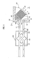
- FIG. 1 is a schematic diagram of illustrating a ventilating system according to the first embodiment of the present invention.
- FIG. 2 is a cross sectional view along I-I' of FIG. 1.
- FIG. 3 is a perspective view of illustrating an air flow when purifying an indoor air with a ventilating system of FIG. 1.
- FIG. 4 is a perspective view of illustrating an air flow when ventilating a room with a ventilating system of FIG. 1.
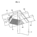
- FIG. 5 and FIG. 6 are perspective views of illustrating examples of installing a ventilating system of FIG. 1 to the inside of a room.
- a case of the ventilating system is provided to a space between a ceiling and a floor of an upper story.
- a ventilating system according to the first embodiment of the present invention has a case 100, wherein one end of the case 100 is projected toward the inside of a room, and the other end is buried in a ceiling. More particularly, as shown in FIG. 1 and FIG. 2, the case 100 has two sides connected with each other for being adhered to the corner of a wall 10, and one front side being round toward the inside of the room.
- the case 100 is formed at a predetermined thickness.
- the case 100 has a quadrant shape formed by dividing a circular shape into four parts.
- the case 100 has the two sides positioned at the corner of the wall 10 for being adhered to the wall 10, an upper end being buried in the ceiling, and a lower end being projected toward the inside of the room.
- the case 100 is positioned, some of the case 100 corresponding to a first height H1 (H1 of FIG. 2) is provided in a space between the ceiling and the bottom of the upper story, and the remaining of the case 100 corresponding to a second height H2 (H2 of FIG. 2) is provided in an inside space of the room under the ceiling.
- H1 first height
- H2 second height
- the ventilating system according to the present invention may be easily installed to a building having a small distance between a floor of a lower story and a floor of an upper story, that is, a small height of one story. If using the ventilating system according to the present invention, it is possible to decrease a height of one story when constructing a new building.
- the ventilating system has an air supplying passage of providing an outdoor air to the inside of the room, an air discharging passage of discharging an indoor air to the outside of the room, and an air circulating passage of circulating the indoor air, wherein each passage flows through the case 100.
- the outside of the room, the case 100, and the inside of the room are in communication with one another.
- the air supplying passage of providing the outdoor air to the inside of the room flows through the space provided between the ceiling and the floor of the upper story, the air supplying passage is connected to the case 100.
- the air supplying passage penetrates the wall 10 without passing through the space provided between the ceiling and the floor of the upper story, and then the air supplying passage is directly connected with the side of the case 10 under the ceiling 20.
- the air supplying passage is comprised of a first port 101 provided in side of the case 100, an air-supplying duct 300 connected with the first port 101, and an air-discharging hole 130 provided in the case 100.
- the first port 101 is provided at any one side of the two sides of the case 100, for being positioned under the ceiling 20.
- the air-supplying duct 300 is provided to penetrate the wall 100, wherein one end of the air-supplying duct 300 is connected with the outside of the room, the other end of the air-supplying duct 300 is connected with the first port 101 under the ceiling 20, and the air-discharging hole 130 is provided in the front of the case 100.
- the first port 101 is provided at a lower portion in the side of the case 100, and the air-discharging hole 130 is provided at a central portion or an upper portion in the front of the case 100 under the ceiling 20.
- a guide passage 160 is provided in the case 100, wherein the guide passage 160 is slantingly provided from the inner upper portion of the case 100 to the air-discharging hole 130.
- a flow-direction guide 131 may be additionally provided in the air-discharging hole 130, for controlling the flow direction of the air discharged to the inside of the room.
- the outdoor air introduced to a lower part of the case 100 through the air-supplying duct 300, moves to an upper part of the case 100, and then is discharged to the inside of the room through the guide passage 160 and the air-discharging hole 130.
- the air supplied to the inside of the room is discharged to a lower space of the room by the guide passage 160, and the air-supplying direction is determined by the flow-direction guide 131.
- an air-supplying fan 320 may be provided in the air-supplying duct 300, as shown in FIG. 1, wherein the air-supplying fan 320 supplies the outdoor air to the inside of the room.
- the inside of the room, the case 100, and the outside of the room are in communication with one another.
- the air discharging passage is connected to the case 100.
- the air discharging passage penetrates the wall 10 without passing through the space formed between the ceiling and the floor of the upper story, and then the air discharging passage is directly connected with the case 100 under the ceiling 20.
- the air discharging passage is comprised of a second inlet 120 provided on the bottom of the case 100, a second port 102 provided in the side of the case 100, and an air-discharging duct 400 connected with the second port 102 and being in communication with the outside of the room.
- the second inlet 120 may be formed of a plurality of slots.
- the second inlet 120 may be formed of a plurality of slots.
- the second port 102 is provided in parallel with the first port 101 at the lower portion in the side of the case 100. Accordingly, the indoor air introduced to the case 100 through the second inlet 120 is discharged to the outside of the room through the air-discharging duct 400.
- the air-discharging duct 400 may have an additional air-discharging fan 410 for discharging the introduced indoor air to the outside of the room. Furthermore, as shown in FIG. 1, another air-discharging fan 411 may be provided in the air-discharging duct 400, for improvement the efficiency in discharging the air.
- the inside of the room is in communication with one point of the air supplying passage inside the case 100.
- the air circulating passage introduces the indoor air to the case 100, and again supplies the introduced air to the inside of the room.
- the air circulating passage is comprised of a first inlet 110 provided on the bottom of the case 100, and the air-discharging hole 130 provided in the front of the case 100.
- the first inlet 110 may be formed of a plurality of slots, wherein the first inlet 110 is provided in parallel with the second inlet 120 on the bottom of the case 100.
- the air circulating passage meets with the air supplying passage in the case 100. Accordingly, the indoor air introduced to the case 100 through the air circulating passage and the outdoor air introduced to the case 100 through the air supplying passage are supplied to the inside of the room through the air-discharging hole 130.
- a preheat exchanger 500 may be additionally provided at an intersection of the air supplying passage and the air discharging passage, and more specifically, at an intersection of the air-supplying duct 300 and the air-discharging duct 400.
- the preheat exchanger 500 includes a plurality of first passages for the flow of the outdoor air, and a plurality of second passages for the flow of the indoor air, wherein the second passages are provided in-between the first passages. Then, a plate is provided between each of the first passages and each of the second passages.
- a fan 210 is provided in the case 100, wherein the fan 210 supplies the air introduced to the case 100 through the air supplying passage or the air circulating passage to the inside of the room.
- the fan 210 supplies the outdoor air introduced to the inside of the case 100 through the air-supplying duct 300 connected with the lower portion in the side of the case 100 to the inside of the room.
- the fan 210 supplies the indoor air flowing into the case 100 through the first inlet 110 formed on the bottom of the case 100 to the inside of the room, again.
- the fan 210 may be formed of a cross flow fan of inhaling the air at an axis direction, and discharging the inhaled air at a radius direction. In this case, it is possible to obtain compactness in the case 100, and to improve the efficiency in the fan 210.
- a division plate 150 may be provided in the case 100, wherein the division plate 150 divides the inside space of the case 100 into a lower space and an upper space. Also, an opening 151 is provided in the division plate 150, for communication between the lower space and the upper space of the case 100. As shown in FIG. 2, the fan 210 is positioned in the opening 151.
- the air introduced to the lower space of the case 100 through the first inlet 110 or the air-supplying duct 300 is provided to the lower side of the fan 210 through the opening 151, and then is discharged to the upper space of the case 100.
- the air discharged to the upper space of the case 100 moves along the guide passage 160 inclined toward the inside of the case 100, and then the air is provided to the inside of the room through the air-discharging hole 130 provided at the lower portion in the front of the case 100.
- an air guide 140 may be additionally provided in the case 100, for separating the air supplying passage from the air discharging passage. As shown in FIG. 2, for example, the air guide 140 is provided to the lower space of the case 100, for separation of the first inlet 110 and the second inlet 120. Accordingly, the air guide 140 guides the air introduced to the case 100 through the air-supplying duct 300 or the first inlet 110 toward the air-discharging hole 130, and guides the air introduced to the case 100 through the second inlet 120 toward the air-discharging duct 400.
- At least one louver 111 is provided in the air circulating passage, for opening and closing the air circulating passage.
- the louver 111 is provided for opening and closing the first inlet 110.
- the first inlet 110 is provided with a plurality of slots, whereby the several louvers 111 are provided for opening and closing the respective slots.
- the louver 111 closes the first inlet 110.
- the louver 111 opens the first inlet 110.
- a damper 310 may be provided in the air supplying passage, for opening and closing the air supplying passage.
- the damper 310 is provided to open and close the first port 101. That is, the damper 310 opens the first port 101 when supplying the outdoor air to the inside of the room through the air supplying passage with the ventilating system. In the meantime, the damper 310 closes the first port 101 when circulating the indoor air by using the air circulating passage with the ventilating system.
- a filter member 600 may be provided in the case 100.
- the filter member 600 is positioned under the fan 210, wherein the filter member 600 purifies the outdoor air introduced to the inside of the case 100 through the air-supplying duct 300 and the indoor air introduced to the inside of the case 100 through the first inlet 110.
- the air purified by the filter member 600 in the case 100 is provided to the room space through the air-discharging hole 130. Accordingly, when ventilating and circulating the room air with the ventilating system according to the present invention, it is possible to provide the purified clean air to the room space since the filter member 600 is provided in the ventilating system.
- the filter member 600 is provided with a dust-collecting filter 610, photo-catalyst 620, and active carbon 630.
- the dust-collecting filter 610 filters dust from the air
- the photo-catalyst 620 and the active carbon 630 are carbon having a strong adsorption capability, and absorb odor from the air.
- the dust-collecting filter 610 may be used of an HEPA (High Efficiency Particulate Arrestor) filter, or an ULPA (Ultra Low Penetration Absolute) filter.
- the HEPA filter can remove particles, such as dust, bacteria, virus, and the like, larger than 0.3micron, up to 99.97%
- the ULPA filter having a better performance than the HEPA filter, can remove particles, such as fine dust, bacteria, dandruff, mold, pollen, radon-decay product, smoke, and the like, with a size ranging 0.1 ⁇ 0.01micron, up to 99.999%.
- the photo-catalyst 620 is one kind of catalysts, wherein catalysis is performed with light energy. At this time, the photo-catalyst 620 may be used of TiO 2 , ZnO, CdS, ZrO 2 , SnO 2 , V 2 O 2 , or WO 3 .
- the aforementioned ventilating system according to the present invention may be installed in various positions according to the structure of the building.
- the case 100 is positioned at the right-side corner of the room.
- the air-supplying duct 200 and the air-discharging duct 300 are connected with the right side of the case 100.
- the case 100 is positioned at the left-side corner of the room.
- the air-supplying duct 200 and the air-discharging duct 300 are connected with the left side of the case 100.
- the ventilating system according to the first embodiment of the present invention is operated as a first operation mode for circulating and purifying the indoor air, and a second operation mode for ventilating the room air by introducing the outdoor air to the inside of the room.
- the damper 310 closes the first port 101, and the louver 111 opens the first inlet 110.
- air-discharging fans 410 and 411 are not driven. Accordingly, the indoor air is not discharged to the outside of the room through the air-discharging duct 400.
- the polluted indoor air is introduced to the lower space of the case 100 through the first inlet 110 formed on the bottom of the case 100.
- the polluted air introduced to the lower space of the case 100 passes through the filter member 600 and the fan 210, and then the filtered clean air is discharged to the upper space of the case 100.
- the filter member 600 is provided with the dust-colleting filter 610, the photo-catalyst 620, and the active carbon 630, which remove the foreign matter from the polluted air, thereby purifying the air.
- the purified clean air is introduced to the upper space of the case 100, and then is provided to the room space through the air-discharging hole 130.
- the damper 310 closes the first port 101, so that the outdoor air is not introduced to the case 100 through the air-supplying duct 300.
- the damper 310 closes the first port 101, so that the outdoor air is not introduced to the case 100 through the air-supplying duct 300.
- the indoor air flows into the case 100, and the indoor air is purified in the case 100.
- the purified air is discharged to the room space.
- the ventilating system according to the present invention continuously circulates and purifies the indoor air.
- the damper 310 opens the first port 101, and the louver 111 closes the first inlet 110.
- the outdoor air flows into the lower space of the case 100 through the air-supplying duct 300 and the first port 101.
- the outdoor air is purified.
- the purified air moves to the upper space of the case 100, and then is provided to the room space through the air-discharging hole 130.
- the louver 111 closes the first inlet 110, whereby the indoor air is not provided to the case 100 through the first inlet 110.
- the indoor air is supplied to the inside of the case 100 through the second inlet 120, and more particularly, to the lower space of the case 100 through the second inlet 120.
- the first inlet 110 and the second inlet 120 are separated from each other by using the air guide 140. Accordingly, the indoor air introduced to the case 100 through the second inlet 120 is not mixed with the outdoor air introduced to the case 100 through the air-supplying duct 300.
- the indoor air introduced to the case 100 through the second inlet 120 is discharged to the outside of the room through the second port 102 and the air-discharging duct 400.
- the preheat exchanger 500 indirectly heat-exchanges the outdoor air flowing through the air-supplying duct 300 with the indoor air flowing through the air-discharging duct 400. That is, when ventilating the room air, the outdoor air introduced to the inside of the room is heated or cooled by the indoor air discharged to the outside of the room, and then the heated or cooled air is provided to the room space, thereby preventing the rapid change on the inside temperature of the room space.
- the louver 111 is provided in the first inlet 110.
- the louver 111 may not be provided.
- the outdoor air is provided to the case 100 through the first port 101, and the indoor air is provided to the case 100 through the first inlet 110.
- the ventilating system continuously introduces the outdoor air to the inside of the room, and simultaneously circulates the indoor air.
- the outdoor air introduced to the inside of the room and the circulating indoor air are purified by the filter member 600 of the case 100, and then the purified air is provided to the room space.
- FIG. 7 is a schematic diagram of illustrating a ventilating system according to the second embodiment of the present invention.
- FIG. 8 is a perspective view of illustrating an air flow when purifying an indoor air with a ventilating system of FIG. 7.
- FIG. 9 is a perspective view of illustrating an air flow when ventilating a room with a ventilating system of FIG. 7.
- the ventilating system according to the second embodiment of the present invention is similar in structure to the ventilating system according to the first embodiment of the present invention, so that the detailed explanation for the structure of the ventilating system according to the second embodiment of the present invention will be omitted. That is, the differences between the first embodiment and the second embodiment will be described in chief.
- the ventilating system according to the second embodiment of the present invention has a case 100, wherein an upper end of the case 100 is buried in a ceiling, and a lower end of the case 100 is projected toward the inside of a room.
- the case is formed in the flat-quadrant shape.
- the case 100 is formed in a flat quadrate shape, as shown in FIG. 8 and FIG. 9.
- the air-discharging hole 130 is provided in the front of the case 100, for discharging the air to the room space.
- air-discharging holes 130 are provided at both sides of the case 100 as well as the front side of the case 100. Accordingly, in case of the ventilating system according to the second embodiment of the present invention, one side of the case 100 is adhered and fixed to a wall of the room, and the air is provided to the inside of the room through the air-discharging holes 130 formed in the front side and the both sides of the case 100, as shown in FIG. 8 and FIG. 9.
- the ventilating system according to the second embodiment of the present invention may have one side being adhered and fixed to the wall of the room, as shown in FIG. 8 and FIG. 9.
- the ventilating system according to the second embodiment of the present invention may be installed at a corner of a ceiling in the room.
- the two sides of the case 100 are adhered to the wall of the room, so that any one of the two air-discharging holes 130 formed on the two sides adjacent to the front side of the case 100 is positioned close to the wall of the room.
- the air discharged through any one air-discharging hole 103 comes into collision with the wall of the room, thereby generating turbulent air and noise.
- a damper 135 is provided to the air-discharging hole 130 adjacent to the wall, for closing the air-discharging hole 130.
- the air inside the case 100 is discharged to the room space through the two air-discharging holes 130 of the case 100, as shown in FIG. 10.
- the ventilating system according to the second embodiment of the present invention is very similar to the ventilating system according to the first embodiment of the present invention in the shape of the case 100, the position of the air-discharging holes 130, and the damper 135 provided in the air-discharging hole 130, as shown in FIG. 7 to FIG. 10. Accordingly, the detailed explanation for the structure and function of the ventilating system according to the second embodiment of the present invention will be omitted.
- the ventilating system according to the present invention has the following advantages.
- the ventilating system it is possible to perform two functions of circulating the indoor air and the purifying the indoor air with one unit, thereby decreasing the cost in purchasing the device of ventilating and purifying the air.
- the air-supplying duct and the air-discharging duct are connected to one side of the case, so that it is possible to lower a height of the ventilating system at a degree corresponding to a height in each duct.
- one end of the case is buried in the ceiling of the room, and the other end of the case is projected toward the room space.
- the air-supplying duct and the air-discharging duct are in direct connection with the case under the ceiling.
- each duct may be connected with one side from the two sides of the case.
- each duct may be selectively connected with one side of the two sides of the case, in due consideration of the structure of outer walls for installing the ventilating system.
- the filter member is provided in the case, so that the purified clean outdoor air and indoor air is provided to the room space, thereby obtaining the more comfortable room environment.
- the cross flow fan is provided to forcibly inhale the indoor air and the outdoor air, so that it is possible to prevent the decrease in the air supplying amount, generated by the increase in the loss of pressure, even in case of the high-performance dust-collecting filter is provided in the filter member.
- a compact ventilating system having an air purifying function which includes a case having one end buried in a ceiling of a room, and the other end projected toward the inside of the room; an air-supplying passage of communicating the outside of the room, the case, and the inside of the room with one another, to supply an outdoor air to the inside of the room; an air-discharging passage of communicating the inside of the room, the case, and the outside of the room with one another, to discharge an indoor air to the outside of the room; an air-circulating passage of communicating the inside of the room with one point of the air-supplying passage inside the case, to introduce the indoor air to the case, and to re-supply the air to the inside of the room; and a fan provided in the case, for supplying the outdoor air introduced to the case through the air-supplying passage to the inside of the room, or re-supplying the indoor air introduced to the case through the air-circulating passage to the inside of the room.
Landscapes
- Engineering & Computer Science (AREA)
- Chemical & Material Sciences (AREA)
- Combustion & Propulsion (AREA)
- Mechanical Engineering (AREA)
- General Engineering & Computer Science (AREA)
- Chemical Kinetics & Catalysis (AREA)
- General Chemical & Material Sciences (AREA)
- Ventilation (AREA)
- Duct Arrangements (AREA)
Applications Claiming Priority (1)
| Application Number | Priority Date | Filing Date | Title |
|---|---|---|---|
| KR1020040059268A KR100686024B1 (ko) | 2004-07-28 | 2004-07-28 | 공기청정 겸용 환기시스템 및 이를 이용한 운전방법 |
Publications (2)
| Publication Number | Publication Date |
|---|---|
| EP1621823A2 true EP1621823A2 (de) | 2006-02-01 |
| EP1621823A3 EP1621823A3 (de) | 2007-11-21 |
Family
ID=35198015
Family Applications (1)
| Application Number | Title | Priority Date | Filing Date |
|---|---|---|---|
| EP05008227A Withdrawn EP1621823A3 (de) | 2004-07-28 | 2005-04-14 | Lüftungssystem |
Country Status (4)
| Country | Link |
|---|---|
| US (1) | US7497771B2 (de) |
| EP (1) | EP1621823A3 (de) |
| KR (1) | KR100686024B1 (de) |
| CN (1) | CN100383464C (de) |
Cited By (11)
| Publication number | Priority date | Publication date | Assignee | Title |
|---|---|---|---|---|
| EP1767873A3 (de) * | 2005-09-22 | 2007-05-02 | LG Electronics, Inc. | Klimaanlage |
| WO2007097547A3 (en) * | 2006-02-20 | 2009-06-11 | Lg Electronics Inc | Air conditioning system and method of controlling the same |
| EP1891982A3 (de) * | 2006-08-22 | 2009-08-05 | Sanyo Electric Co., Ltd. | Luftfiltervorrichtung mit Mechanismus zur Entfernung von Fremdstoffen |
| EP2098796A1 (de) * | 2008-03-04 | 2009-09-09 | New Evelino Srl | Kompakte Vorrichtung für Luftwechsel mit Wärmerückgewinnung |
| EP2290296A1 (de) * | 2009-07-31 | 2011-03-02 | Kampmann GmbH | Klimatisierungsvorrichtung zum Einbau in eine abgehängte Decke mit Frischluftzufuhr |
| EP2014997A4 (de) * | 2006-04-17 | 2011-11-16 | Daikin Ind Ltd | Klimaanlage |
| EP2017542A4 (de) * | 2006-04-21 | 2011-12-07 | Daikin Ind Ltd | Klimaanlage |
| CN111156678A (zh) * | 2020-02-25 | 2020-05-15 | 广东美的制冷设备有限公司 | 风管结构、新风模块及空调器 |
| CN117515707A (zh) * | 2022-07-29 | 2024-02-06 | 宁波奥克斯电气股份有限公司 | 一种新风模块及空调器 |
| CN117515711A (zh) * | 2022-07-29 | 2024-02-06 | 宁波奥克斯电气股份有限公司 | 一种新风模块及空调器 |
| EP4098950B1 (de) * | 2021-05-24 | 2025-07-30 | LG Electronics Inc. | Klimatisierungssystem |
Families Citing this family (22)
| Publication number | Priority date | Publication date | Assignee | Title |
|---|---|---|---|---|
| WO2007058418A2 (en) * | 2005-11-21 | 2007-05-24 | Lg Electronics, Inc. | Air conditioning system |
| GB0800664D0 (en) * | 2008-01-15 | 2008-02-20 | Titon Hardware | Housings for ventilation systems |
| US8485579B2 (en) * | 2011-03-17 | 2013-07-16 | Western Digital (Fremont), Llc | Vacuum pickup assemblies for picking up articles and minimizing contamination thereof |
| US9551496B2 (en) | 2011-04-20 | 2017-01-24 | Dan P. McCarty | Displacement-induction neutral wall air terminal unit |
| US9074789B2 (en) * | 2013-03-04 | 2015-07-07 | John P. Hanus | Method and apparatus to provide ventilation for a building |
| KR101503857B1 (ko) * | 2013-08-01 | 2015-03-19 | (주)정민 | 도어가 구비된 전열교환기 |
| WO2016077268A1 (en) * | 2014-11-10 | 2016-05-19 | Internal Air Flow Dynamics, Llc | Device, system, and method for eliminating air pockets, eliminating air stratification, minimizing inconsistent temperature, and increasing internal air turns |
| CN106322512B (zh) * | 2015-07-01 | 2023-04-07 | 青岛海尔智能技术研发有限公司 | 一种新型壁挂式空调器 |
| US10403328B2 (en) * | 2016-01-29 | 2019-09-03 | Western Digital Technologies, Inc. | Acoustic attenuation in data storage enclosures |
| CN106592742A (zh) * | 2016-12-13 | 2017-04-26 | 刘俊华 | 卫生间除味系统及其施工方法 |
| CN110319500B (zh) * | 2018-03-30 | 2024-09-03 | 珠海格力电器股份有限公司 | 空调室内机 |
| CN111238117B (zh) * | 2018-11-29 | 2021-04-16 | 宁波方太厨具有限公司 | 一种除异味冰箱 |
| KR102111216B1 (ko) * | 2018-11-30 | 2020-05-14 | 자이에스앤디 주식회사 | 공기 청정기 및 이를 갖는 실내 공기 청정 시스템 |
| EP3971488A1 (de) | 2020-09-18 | 2022-03-23 | Carrier Corporation | Luftreiniger mit rückluftgitter |
| KR102259561B1 (ko) | 2020-11-10 | 2021-06-02 | (주)아지즈 | 환기 겸용 공기청정기 |
| TWI832026B (zh) * | 2020-12-21 | 2024-02-11 | 研能科技股份有限公司 | 車內空汙防治解決方法 |
| CN112815394B (zh) * | 2021-02-23 | 2024-12-31 | 珠海格力电器股份有限公司 | 通风设备及具有其的空调器 |
| JP7414774B2 (ja) * | 2021-06-28 | 2024-01-16 | 矢崎総業株式会社 | 樹脂成形体、樹脂成形体の製造方法、及び、液圧制御装置 |
| CN117515706B (zh) * | 2022-07-29 | 2026-01-23 | 宁波奥克斯电气有限公司 | 一种新风模块及空调器 |
| CN117515710B (zh) * | 2022-07-29 | 2025-12-16 | 宁波奥克斯电气有限公司 | 新风模块和空调器 |
| US12504185B2 (en) | 2022-10-05 | 2025-12-23 | Daniel P. McCarty | Integrated ventilation and heat recovery terminal |
| CN116717846B (zh) * | 2023-05-17 | 2025-10-24 | 珠海格力电器股份有限公司 | 一种室内换风装置及空调器 |
Citations (3)
| Publication number | Priority date | Publication date | Assignee | Title |
|---|---|---|---|---|
| JPH08178349A (ja) | 1994-12-24 | 1996-07-12 | Daikin Ind Ltd | 全熱交換気一体形空調機 |
| JPH08226668A (ja) | 1995-02-20 | 1996-09-03 | Mitsubishi Electric Corp | 天井埋込型換気空調ユニット |
| JP2001227772A (ja) | 1999-12-03 | 2001-08-24 | Mitsubishi Heavy Ind Ltd | 埋込型空気調和機及び空気調和システム |
Family Cites Families (16)
| Publication number | Priority date | Publication date | Assignee | Title |
|---|---|---|---|---|
| JPH0744991B2 (ja) | 1987-11-06 | 1995-05-17 | 松下精工株式会社 | バス乾燥機 |
| US4955997A (en) * | 1989-05-10 | 1990-09-11 | Robertson Iii Elmer W | Flush mounted ceiling air cleaner |
| JPH0468246A (ja) * | 1990-07-05 | 1992-03-04 | Mitsubishi Electric Corp | 換気扇 |
| JPH0515718A (ja) * | 1991-07-12 | 1993-01-26 | Matsushita Seiko Co Ltd | 外気導入型空気清浄機 |
| JP3020695U (ja) * | 1995-05-17 | 1996-02-06 | 耕三 福田 | 空気循環装置 |
| US5934362A (en) * | 1997-01-21 | 1999-08-10 | Tele-Flow, Inc. | Combination bath fan, register box, air conditioning and heating boot |
| JPH10281523A (ja) | 1997-04-04 | 1998-10-23 | Shinwa Seisakusho:Kk | 全熱交換型換気装置 |
| US5987908A (en) * | 1997-09-25 | 1999-11-23 | Floratech Industries | Self-contained air conditioner with discharge-air filter |
| US6217281B1 (en) * | 1999-06-30 | 2001-04-17 | Industrial Technology Research Institute | Low-noise fan-filter unit |
| DE29916321U1 (de) | 1999-09-16 | 1999-12-23 | M + W Zander Facility Engineering GmbH + Co. KG, 70499 Stuttgart | Reinstlufteinrichtung für den Pharmazie-, Lebensmittel- und biotechnischen Bereich |
| CA2321243A1 (en) * | 1999-11-18 | 2001-05-18 | Shinyo Co., Ltd. | Air cycle houses and house ventilation system |
| JP3739989B2 (ja) * | 2000-03-08 | 2006-01-25 | ミドリ安全株式会社 | 換気機能付空気清浄装置 |
| JP2001304612A (ja) * | 2000-04-14 | 2001-10-31 | Daikin Ind Ltd | 天井埋込型空気調和機用室内機 |
| KR100845837B1 (ko) * | 2002-01-24 | 2008-07-14 | 엘지전자 주식회사 | 환기장치 |
| US6619063B1 (en) * | 2002-03-19 | 2003-09-16 | Anthony Lee Brumett | Indoor air treatment system with HEPA filtration |
| US6569010B1 (en) * | 2002-04-25 | 2003-05-27 | Nuclimate Air Quality Systems, Inc. | Induced air distribution system |
-
2004
- 2004-07-28 KR KR1020040059268A patent/KR100686024B1/ko not_active Expired - Fee Related
-
2005
- 2005-04-14 EP EP05008227A patent/EP1621823A3/de not_active Withdrawn
- 2005-04-15 US US11/106,607 patent/US7497771B2/en not_active Expired - Fee Related
- 2005-04-19 CN CNB2005100659611A patent/CN100383464C/zh not_active Expired - Fee Related
Patent Citations (3)
| Publication number | Priority date | Publication date | Assignee | Title |
|---|---|---|---|---|
| JPH08178349A (ja) | 1994-12-24 | 1996-07-12 | Daikin Ind Ltd | 全熱交換気一体形空調機 |
| JPH08226668A (ja) | 1995-02-20 | 1996-09-03 | Mitsubishi Electric Corp | 天井埋込型換気空調ユニット |
| JP2001227772A (ja) | 1999-12-03 | 2001-08-24 | Mitsubishi Heavy Ind Ltd | 埋込型空気調和機及び空気調和システム |
Cited By (15)
| Publication number | Priority date | Publication date | Assignee | Title |
|---|---|---|---|---|
| EP1767873A3 (de) * | 2005-09-22 | 2007-05-02 | LG Electronics, Inc. | Klimaanlage |
| WO2007097547A3 (en) * | 2006-02-20 | 2009-06-11 | Lg Electronics Inc | Air conditioning system and method of controlling the same |
| CN101668994B (zh) * | 2006-02-20 | 2012-05-30 | Lg电子株式会社 | 空调系统及其控制方法 |
| EP2014997A4 (de) * | 2006-04-17 | 2011-11-16 | Daikin Ind Ltd | Klimaanlage |
| US8511108B2 (en) | 2006-04-21 | 2013-08-20 | Daikin Industries, Ltd. | Air conditioning unit |
| EP2017542A4 (de) * | 2006-04-21 | 2011-12-07 | Daikin Ind Ltd | Klimaanlage |
| EP1891982A3 (de) * | 2006-08-22 | 2009-08-05 | Sanyo Electric Co., Ltd. | Luftfiltervorrichtung mit Mechanismus zur Entfernung von Fremdstoffen |
| EP2098796A1 (de) * | 2008-03-04 | 2009-09-09 | New Evelino Srl | Kompakte Vorrichtung für Luftwechsel mit Wärmerückgewinnung |
| EP2290296A1 (de) * | 2009-07-31 | 2011-03-02 | Kampmann GmbH | Klimatisierungsvorrichtung zum Einbau in eine abgehängte Decke mit Frischluftzufuhr |
| EP2405207A1 (de) * | 2009-07-31 | 2012-01-11 | Kampmann GmbH | Klimatisierungsvorrichtung zum einbau in eine raumdecke |
| CN111156678A (zh) * | 2020-02-25 | 2020-05-15 | 广东美的制冷设备有限公司 | 风管结构、新风模块及空调器 |
| EP4098950B1 (de) * | 2021-05-24 | 2025-07-30 | LG Electronics Inc. | Klimatisierungssystem |
| US12480667B2 (en) | 2021-05-24 | 2025-11-25 | Lg Electronics Inc. | Air-conditioning system |
| CN117515707A (zh) * | 2022-07-29 | 2024-02-06 | 宁波奥克斯电气股份有限公司 | 一种新风模块及空调器 |
| CN117515711A (zh) * | 2022-07-29 | 2024-02-06 | 宁波奥克斯电气股份有限公司 | 一种新风模块及空调器 |
Also Published As
| Publication number | Publication date |
|---|---|
| US7497771B2 (en) | 2009-03-03 |
| US20060035579A1 (en) | 2006-02-16 |
| CN100383464C (zh) | 2008-04-23 |
| KR100686024B1 (ko) | 2007-02-22 |
| KR20060010534A (ko) | 2006-02-02 |
| CN1727786A (zh) | 2006-02-01 |
| EP1621823A3 (de) | 2007-11-21 |
Similar Documents
| Publication | Publication Date | Title |
|---|---|---|
| US7497771B2 (en) | Ventilating system | |
| US7591720B2 (en) | Ventilating system | |
| US7591867B2 (en) | Ventilation system | |
| CN206531233U (zh) | 地面式热回收换气装置 | |
| KR101237259B1 (ko) | 실내공기 청정기능을 갖는 필터 및 열교환기가 내장된 창문형 환기장치 | |
| CN206468252U (zh) | 具有热交换和空气净化功能的窗户通风系统 | |
| WO2022012633A1 (zh) | 一种空调的室内机及空调 | |
| KR102081237B1 (ko) | 환기 및 에너지 절감형 공기청정기 | |
| KR102079211B1 (ko) | 하부로 공기가 유동되는 대용량 필터를 구비한 전열교환기 | |
| KR102282099B1 (ko) | 바이패스 챔버가 구비된 전열교환기 | |
| KR20050080287A (ko) | 공기청정장치 일체형 환기시스템 | |
| KR20060024742A (ko) | 청정모드기능을 갖는 전열교환기 | |
| KR100539568B1 (ko) | 공기청정겸용 환기시스템 | |
| KR20000056583A (ko) | 공기 조화기 | |
| CN1821672B (zh) | 通风系统 | |
| KR101995119B1 (ko) | 창문설치형 공기청정기 | |
| JP2555814B2 (ja) | 給気量可変式空気清浄システム | |
| KR20060089775A (ko) | 환기겸용 공기청정기 | |
| KR100587313B1 (ko) | 공기청정장치 일체형 환기시스템 | |
| KR102369733B1 (ko) | 열회수 환기장치 및 공기청정기의 연동 운전을 이용한 실내공기 청정시스템 | |
| KR200407836Y1 (ko) | 환기유니트를 이용한 공기청정시스템 | |
| KR102067232B1 (ko) | 벽부형 전열교환기 | |
| KR20180087016A (ko) | 자연 급기장치 및 이를 구비한 창문형 하이브리드 환기시스템 | |
| KR20160146001A (ko) | 다기능 자동환기장치 | |
| JP2015152273A (ja) | 室内空気清浄システム |
Legal Events
| Date | Code | Title | Description |
|---|---|---|---|
| PUAI | Public reference made under article 153(3) epc to a published international application that has entered the european phase |
Free format text: ORIGINAL CODE: 0009012 |
|
| 17P | Request for examination filed |
Effective date: 20050414 |
|
| AK | Designated contracting states |
Kind code of ref document: A2 Designated state(s): AT BE BG CH CY CZ DE DK EE ES FI FR GB GR HU IE IS IT LI LT LU MC NL PL PT RO SE SI SK TR |
|
| AX | Request for extension of the european patent |
Extension state: AL BA HR LV MK YU |
|
| PUAL | Search report despatched |
Free format text: ORIGINAL CODE: 0009013 |
|
| AK | Designated contracting states |
Kind code of ref document: A3 Designated state(s): AT BE BG CH CY CZ DE DK EE ES FI FR GB GR HU IE IS IT LI LT LU MC NL PL PT RO SE SI SK TR |
|
| AX | Request for extension of the european patent |
Extension state: AL BA HR LV MK YU |
|
| AKX | Designation fees paid |
Designated state(s): ES FR GB |
|
| REG | Reference to a national code |
Ref country code: DE Ref legal event code: 8566 |
|
| 17Q | First examination report despatched |
Effective date: 20110617 |
|
| STAA | Information on the status of an ep patent application or granted ep patent |
Free format text: STATUS: THE APPLICATION IS DEEMED TO BE WITHDRAWN |
|
| 18D | Application deemed to be withdrawn |
Effective date: 20141101 |