EP1621838A2 - Réfrigérateur avec un élévateur de panier - Google Patents
Réfrigérateur avec un élévateur de panier Download PDFInfo
- Publication number
- EP1621838A2 EP1621838A2 EP05014717A EP05014717A EP1621838A2 EP 1621838 A2 EP1621838 A2 EP 1621838A2 EP 05014717 A EP05014717 A EP 05014717A EP 05014717 A EP05014717 A EP 05014717A EP 1621838 A2 EP1621838 A2 EP 1621838A2
- Authority
- EP
- European Patent Office
- Prior art keywords
- link
- basket
- frame
- refrigerator
- door
- Prior art date
- Legal status (The legal status is an assumption and is not a legal conclusion. Google has not performed a legal analysis and makes no representation as to the accuracy of the status listed.)
- Granted
Links
Images


Classifications
-
- F—MECHANICAL ENGINEERING; LIGHTING; HEATING; WEAPONS; BLASTING
- F25—REFRIGERATION OR COOLING; COMBINED HEATING AND REFRIGERATION SYSTEMS; HEAT PUMP SYSTEMS; MANUFACTURE OR STORAGE OF ICE; LIQUEFACTION SOLIDIFICATION OF GASES
- F25D—REFRIGERATORS; COLD ROOMS; ICE-BOXES; COOLING OR FREEZING APPARATUS NOT OTHERWISE PROVIDED FOR
- F25D23/00—General constructional features
- F25D23/02—Doors; Covers
-
- F—MECHANICAL ENGINEERING; LIGHTING; HEATING; WEAPONS; BLASTING
- F25—REFRIGERATION OR COOLING; COMBINED HEATING AND REFRIGERATION SYSTEMS; HEAT PUMP SYSTEMS; MANUFACTURE OR STORAGE OF ICE; LIQUEFACTION SOLIDIFICATION OF GASES
- F25D—REFRIGERATORS; COLD ROOMS; ICE-BOXES; COOLING OR FREEZING APPARATUS NOT OTHERWISE PROVIDED FOR
- F25D25/00—Charging, supporting, and discharging the articles to be cooled
- F25D25/02—Charging, supporting, and discharging the articles to be cooled by shelves
- F25D25/024—Slidable shelves
- F25D25/025—Drawers
-
- A—HUMAN NECESSITIES
- A47—FURNITURE; DOMESTIC ARTICLES OR APPLIANCES; COFFEE MILLS; SPICE MILLS; SUCTION CLEANERS IN GENERAL
- A47B—TABLES; DESKS; OFFICE FURNITURE; CABINETS; DRAWERS; GENERAL DETAILS OF FURNITURE
- A47B46/00—Cabinets, racks or shelf units, having one or more surfaces adapted to be brought into position for use by extending or pivoting
-
- A—HUMAN NECESSITIES
- A47—FURNITURE; DOMESTIC ARTICLES OR APPLIANCES; COFFEE MILLS; SPICE MILLS; SUCTION CLEANERS IN GENERAL
- A47B—TABLES; DESKS; OFFICE FURNITURE; CABINETS; DRAWERS; GENERAL DETAILS OF FURNITURE
- A47B51/00—Cabinets with means for moving compartments up and down
-
- A—HUMAN NECESSITIES
- A47—FURNITURE; DOMESTIC ARTICLES OR APPLIANCES; COFFEE MILLS; SPICE MILLS; SUCTION CLEANERS IN GENERAL
- A47B—TABLES; DESKS; OFFICE FURNITURE; CABINETS; DRAWERS; GENERAL DETAILS OF FURNITURE
- A47B67/00—Chests; Dressing-tables; Medicine cabinets or the like; Cabinets characterised by the arrangement of drawers
- A47B67/04—Chests of drawers; Cabinets characterised by the arrangement of drawers
-
- F—MECHANICAL ENGINEERING; LIGHTING; HEATING; WEAPONS; BLASTING
- F25—REFRIGERATION OR COOLING; COMBINED HEATING AND REFRIGERATION SYSTEMS; HEAT PUMP SYSTEMS; MANUFACTURE OR STORAGE OF ICE; LIQUEFACTION SOLIDIFICATION OF GASES
- F25D—REFRIGERATORS; COLD ROOMS; ICE-BOXES; COOLING OR FREEZING APPARATUS NOT OTHERWISE PROVIDED FOR
- F25D25/00—Charging, supporting, and discharging the articles to be cooled
- F25D25/02—Charging, supporting, and discharging the articles to be cooled by shelves
-
- A—HUMAN NECESSITIES
- A47—FURNITURE; DOMESTIC ARTICLES OR APPLIANCES; COFFEE MILLS; SPICE MILLS; SUCTION CLEANERS IN GENERAL
- A47B—TABLES; DESKS; OFFICE FURNITURE; CABINETS; DRAWERS; GENERAL DETAILS OF FURNITURE
- A47B2210/00—General construction of drawers, guides and guide devices
- A47B2210/17—Drawers used in connection with household appliances
-
- F—MECHANICAL ENGINEERING; LIGHTING; HEATING; WEAPONS; BLASTING
- F25—REFRIGERATION OR COOLING; COMBINED HEATING AND REFRIGERATION SYSTEMS; HEAT PUMP SYSTEMS; MANUFACTURE OR STORAGE OF ICE; LIQUEFACTION SOLIDIFICATION OF GASES
- F25D—REFRIGERATORS; COLD ROOMS; ICE-BOXES; COOLING OR FREEZING APPARATUS NOT OTHERWISE PROVIDED FOR
- F25D23/00—General constructional features
- F25D23/02—Doors; Covers
- F25D23/021—Sliding doors
-
- F—MECHANICAL ENGINEERING; LIGHTING; HEATING; WEAPONS; BLASTING
- F25—REFRIGERATION OR COOLING; COMBINED HEATING AND REFRIGERATION SYSTEMS; HEAT PUMP SYSTEMS; MANUFACTURE OR STORAGE OF ICE; LIQUEFACTION SOLIDIFICATION OF GASES
- F25D—REFRIGERATORS; COLD ROOMS; ICE-BOXES; COOLING OR FREEZING APPARATUS NOT OTHERWISE PROVIDED FOR
- F25D25/00—Charging, supporting, and discharging the articles to be cooled
- F25D25/005—Charging, supporting, and discharging the articles to be cooled using containers
-
- F—MECHANICAL ENGINEERING; LIGHTING; HEATING; WEAPONS; BLASTING
- F25—REFRIGERATION OR COOLING; COMBINED HEATING AND REFRIGERATION SYSTEMS; HEAT PUMP SYSTEMS; MANUFACTURE OR STORAGE OF ICE; LIQUEFACTION SOLIDIFICATION OF GASES
- F25D—REFRIGERATORS; COLD ROOMS; ICE-BOXES; COOLING OR FREEZING APPARATUS NOT OTHERWISE PROVIDED FOR
- F25D25/00—Charging, supporting, and discharging the articles to be cooled
- F25D25/04—Charging, supporting, and discharging the articles to be cooled by conveyors
Definitions
- the present invention relates to a refrigerator having a basket lift apparatus, and particularly, to a refrigerator having a basket lift apparatus capable of improving convenience for a user by lifting a basket when the basket received in a lower portion of a body is taken out.
- Figure 1 is a perspective view of a refrigerator in accordance with the conventional art
- Figure 2 is a sectional view of a refrigerator showing that a basket is received in a body.
- the conventional refrigerator includes: a body 1 whose front is open and which has a receiving space; an upper cooling chamber 3 disposed at an upper side of the body 1, having a pair of upper doors 2 opened in both directions, and storing food items; and a lower cooling chamber 6 disposed at a lower side of the body 1, separated from the upper cooling chamber 3 by a partition wall 4, and having a lower door 5 which is slidingly opened.
- a machine room 8 having therein a compressor 7 and the like for generating cool air to be supplied to the upper cooling chamber 3 and the lower cooling chamber 6 is formed at the rear of the body 1.
- a basket 9 for receiving frozen food items is disposed at the lower cooling chamber 6 and can slide in the front and rear direction (back and forth).
- the lower door 5 is fixed at the front of the basket 9.
- a user pulls the lower door 5 to open the basket 9 and pushes it to close the basket 9.
- a guide rail 10 is installed between the basket 9 and an inner surface of the lower cooling chamber 6 and guides the basket to allow the basket 9 to slide in the front and rear direction (back and forth).
- the refrigerator in accordance with the conventional art having such a structure has a basket at its lower portion (i.e., the basket is installed at a lower side), a user has to stoop or crouch down to put in and/or take out food items into and/or from the basket, which causes inconvenience for the user.
- an object of the present invention is to provide a refrigerator having a basket lift apparatus capable of improving convenience for the user by lifting up a basket when the basket disposed at a lower portion of a body is opened.
- a refrigerator comprising: a refrigerator body having cooling chambers; a frame slidingly received in a cooling chamber disposed at a lower portion of the body; a basket put on the frame and storing food items; a door positioned at the front of the frame and hingedly connected to the frame; a first link, one side of the first link being rotatably connected to the basket and the other side being slidably coupled with the frame; a second link disposed across the first link, one side of the second link being rotatably connected to the basket and the other side being slidably coupled with the frame; and a link drive unit connected to the first link or the second link and driving the link to allow the basket to ascend with respect to the frame.
- a refrigerator comprising: a refrigerator body having cooling chambers; a frame slidingly received in a cooling chamber disposed at a lower portion of the body; a basket put on the frame and storing food items; a lower door positioned at the front of the frame and rotatably connected to the frame; a first link, one side of the first link being rotatably coupled with the frame and the other side being rotatably coupled with the basket; a second link disposed across the first link, one side of the second link being rotatably coupled with the basket and the other side being slidably coupled with the frame; a connection link, one side of the connection link being connected to the lower door and the other side being connected to the first link; and a fixing unit installed at the lower door and fixing the lower door to a specific position.
- a plurality of embodiments of a refrigerator having a basket lift apparatus in accordance with the present invention may exist, and hereinafter, the most preferred embodiment will be described.
- Figure 3 is a perspective view of a refrigerator in accordance with a first embodiment of the present invention
- Figure 4 is a side view of a basket lift apparatus in accordance with the first embodiment of the present invention.
- the refrigerator in accordance with the present invention includes: a refrigerator body 15 having cooling chambers; a frame 26 slidingly received in a cooling chamber disposed at a lower portion of the body 15; a basket 20 put on the frame 26 and storing food items; a lower door 22 positioned at the front of the frame 26 and integrally connected to the frame 26; a first link 28 whose one side is rotatably connected to the basket 20 and the other side is slidably coupled with the frame 26; a second link 30 disposed across the first link 28, whose one side is rotatably connected to the basket 20 and the other side is slidably coupled with the frame 26; and a link drive unit (not shown) connected to the first link 28 or the second link 30 and driving the link to allow the basket 20 to ascend with respect to the frame 26.
- the body 15 includes: an upper cooling chamber 14 disposed at its upper portion and provided with a pair of upper doors 12 opened in both directions, and a lower cooling chamber 18 separated from the upper cooling chamber 14 by a partition wall 16 and disposed at a lower portion of the body 15.
- the upper cooling chamber 14 is used as a refrigerating chamber for storing chilled food items
- the lower cooling chamber 18 is used as a freezing chamber for storing frozen food items.
- a lower door 22 is disposed at the front of the lower cooling chamber 18 and is moved in a front and rear direction of the body 15 such that the basket 20 is taken out of or put into the lower cooling chamber 18.
- a plurality of drawers 24 storing food items and put in or taken out in a front and rear direction are disposed at an upper side of the lower cooling chamber 18.
- a machine room (not shown) that can receive a compressor and the like may be disposed at one side in the lower cooling chamber 18.
- the lower door 22 has a handle 21 at its front so that a user can hold and pull the lower door 22.
- An operation switch 55 is installed at one side of the handle 21 and can be operated to allow the basket 20 to ascend when the basket is taken out.
- the first link 28 is formed in a bar type having a certain length and is disposed inclined at a certain angle. One end of the first link 28 is slidably coupled with a first rail portion 32 formed at a lower end of the frame 26, and its other end is hingedly connected to a shaft 33 formed at a lower end of the basket 20.
- the second link 30 is formed in a bar type having a certain length. One end of the second link 30 is slidably coupled with the second rail portion 134 formed at a lower end of the frame 26 and its other end is hingedly connected to a shaft 35 formed at a lower end of the basket 20.
- the frame 26 is formed as a quadrangular box shape having a space where the basket 20 can be placed.
- Two guide rails 40 along which the frame 26 slides in a front and rear direction are installed between a lower surface of the frame 26 and a bottom of the lower cooling chamber 18.
- Each guide rail 40 includes: a fixed rail 41 fixed on a bottom of the lower cooling chamber 18; a middle rail 42 slidably connected with the fixed rail 41; and a moving rail 43 slidably connected with the middle rail 42 and fixed on a bottom surface of the frame 26.
- Figure 5 is a cross sectional view of a link drive unit in accordance with the first embodiment of the present invention
- Figure 6 is a sectional view taken along line VI-VI of Figure 5.
- the link drive unit 70 includes a pair of pulleys 73 disposed at both edges of the frame 26 along a direction in which the frame 26 moves, and separated from each other at a predetermined distance; a belt 75 movably coupled with a pair of pulley 73; and a driving motor 77 for moving the belt 75.
- a driving motor 77 for rotating the pulley 73 forward or backward is installed at a pulley 73 disposed at the rear, one of a pair of pulleys 73.
- a lower end of the first link 28 is integrally and movably coupled with a lower surface of the belt 75.
- a lower end of the second link 30 is integrally and movably coupled with an upper surface of the belt 75 such that the second link 30 can move in an opposite direction to a moving direction of the first link when the belt 75 runs.
- the basket may be slid by a sprocket and a chain, instead of the pulley 73 and the belt 75.
- first link 28 and the second link 30 are slidably coupled with the frame, and their upper ends are rotatably coupled with the basket.
- upper ends of the first link 28 and the second link 30 may be slidably coupled with the basket, and their lower ends may be rotatably coupled with the frame.
- Figure 7 is a view showing the operation of the basket lift apparatus in accordance with the first embodiment of the present invention.
- the user when putting and/or taking out food items into from the basket 20, the user holds and pulls the handle 21 frontward. Then, the rail is extended, thereby allowing the frame 26 and the lower door 22 to be taken out frontward.
- the user When intending to lift up the basket 20, the user inputs a signal with the operation switch 55.
- a control unit (not shown) having received the inputted signal controls the driving motor 77 to thereby rotate the driving motor 77 so that lower ends of the first link 28 and the second link 30 approach each other.
- the belt 75 runs, allowing the lower ends of the first link 28 and the second link 30 to slide along the first rail portion 32 and the second rail portion 34.
- the lower ends of the first link 28 and the second link 30 move in a direction that the two approach each other, upper ends of the first link 28 and the second link 30 ascend vertically. Accordingly, the basket 20 ascends, being separated from the basket 20.
- the driving motor 77 rotates in a direction that the lower ends of the first link 28 and the second link 30 recede from each other.
- the basket 20 descends, getting near to the frame 26.
- the user holds and presses the handle 21 rearward, so that the guide rail 40 is shortened.
- the frame 26 and the basket 20 are received in the lower cooling chamber 18, and the lower door 22 blocks a front aperture of the lower cooling chamber 18.
- Figure 8 is a cross sectional view showing a link drive unit in accordance with a second embodiment of the present invention.
- the same reference numerals designate the same part as those of the first embodiment, and the detailed descriptions thereon will be omitted.
- the link drive unit 70 can move along a direction that the frame 26 moves and include a solenoid 78 provided with a rod 79 whose one side is integrally connected with the belt 75. Namely, the rod 79 is moved forward or backward as an electric signal is supplied to the solenoid 78, thereby driving the belt 75.
- the solenoid 78 is used for the driving motor.
- Figure 9 is a side view of a basket lift apparatus in accordance with a third embodiment of the present invention
- Figure 10 is a cross sectional view of a link drive unit in accordance with the third embodiment of the present invention.
- the same reference numerals designate the same part as those of the first embodiment, and the detailed descriptions thereon will be omitted.
- one side of a first link 128 is rotatably coupled with the frame 26, and the other side is slidably coupled with the basket 20.
- a second link 130 is disposed across the first link 128.
- One side of the second link 130 is slidably coupled with the frame 26, and its other side is rotatably coupled with the basket 20.
- One side of the first link 128 is rotatably coupled with one side of the frame 26, and a fourth rail portion 134 is formed at the other side of the frame 26 so that one side of the second link 130 can slide therealong in a direction that the frame 26 moves.
- a third rail portion 132 along which the other side of the first link 128 slides is formed at one side of the basket 20, and the other side of the second link 130 is rotatably coupled with the other side of the basket 20 by a shaft 66.
- the shaft 66 is provided with a link spring 67 for applying an elastic force in a direction that the second link 130 rotates to lift up the basket 20.
- the link spring 67 provides an elastic force which makes the first link 128 stand. When the basket 20 ascends, the link spring 67 provides an elastic force thereto, thereby facilitating the ascent of the basket 20.
- the link spring 67 is a spiral spring or a torsion spring.
- the link drive unit 80 includes: a gear motor 85 integrally and rotatably coupled with a shaft 62 formed at a lower end of the first link 128; a gear 83 engaged with the gear motor 85; and a driving motor 87 integrally coupled with the gear 83 and rotating the gear 83.
- first link 128 and a lower end of the second link 130 slide and a lower end of the first link 128 and an upper end of the second link 130 rotatably coupled with the frame 26 and the basket 20, respectively, in the present embodiment, the opposite construction may be employed.
- the shaft 62 formed at the lower end of the first link 128 is rotated by using the driving motor 87 in the present embodiment.
- an upper end of the second link 130 may be rotated, or an upper end of the first link 128 and/or a lower end of the second link may be slid by using a driving motor, a solenoid or the like.
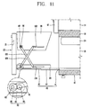
- FIG 11 is a view showing operation of the basket lift apparatus in accordance with the third embodiment of the present invention.
- a user when intending to move the basket 20 upwards in a state that the basket 20 has been taken out, a user operates an operation switch 55 disposed outside the lower door 22.
- the link driving motor 87 rotates to rotate the first link upwardly, and thus the basket 20 moves upwardly with respect to the frame 26.
- the lower end of the second link 130 moves along a fourth rail portion 134.
- the link spring 67 applies an elastic force to the second link 130, thereby facilitating the ascent of the basket 20.
- the link driving motor 87 rotates to rotate the first link 128 downwardly. Accordingly, the upper end of the first link 128 and the lower end of the second link 130 slide to the rear areas of the basket 20 and the frame 26, respectively, and the basket 20 descends to come in contact with and be supported by the frame 26.
- Figure 12 is a side view of a basket lift apparatus in accordance with a fourth embodiment of the present invention
- Figure 13 is a cross sectional view of a link drive unit in accordance with the fourth embodiment of the present invention.
- the same reference numerals designate the same part as those of the first embodiment, and the detailed descriptions thereon will be omitted.
- a refrigerator in accordance with the present invention includes: a refrigerator body 15 having cooling chambers; a frame 226 slidingly received in a cooling chamber disposed at a lower portion of the body 15; a basket 20 put on the frame 226 and storing food items; a lower door 22 positioned at the front of the frame 226 and rotatably connected with the frame 226; a first link 228 whose one side is rotatably coupled with the frame 226 and the other side is rotatably coupled with the basket 20; a second link 230 disposed across the first link 228, whose one side is rotatably coupled with the basket 20 and the other side is slidably coupled with the frame 226; a connection link 300 whose one side is connected with the lower door 22 and the other side is connected to the first link 228; and a fixing unit 400 installed at the lower door 22 and fixing the lower door 22 at a specific position.
- a hinge portion 143 is formed at a lower portion of the lower door 22 and is rotatably supported thereby.
- a lower end of the first link 228 is rotatably connected to a front area of the frame, and a link spring 68 is connected to a shaft 62 formed at a lower end of the first link 228 so that the link 228 can rotate, moving the basket 20 upwards. Also, a rail portion 234 along which a lower end of the second link 230 slides in a front and rear direction is formed at a rear area of the frame 226.
- connection link 300 is rotatably connected to the lower door 22, and its other end is rotatably connected to a specific place.
- the fixing unit 400 includes: a first door fixing unit 410 formed at a rear surface of the lower door 22 and allowing the lower door 22 to remain in a downwardly-rotated (i.e., opened) state as the basket 20 ascends; and a second door fixing unit 420 allowing the lower door 22 to remain perpendicular to the frame 226 as the basket 20 descends.
- the first door fixing unit 410 includes: a rod 411 having a certain length and rotatably connected to a rear surface of the lower door 22 by a shaft 414; a stopping hole 415 formed at the frame 226 such that the rod 411 passes therethrough; and a catching protrusion 412 formed at an end of the rod 411 and getting caught in the stopping hole 415.
- the rod 411 preferably has an inclined portion 413 so that the rod 411 can easily pass through the stopping hole 415 when the lower door 22 rotates.
- Such a first door fixing unit 410 can allow the lower door 22 to maintain a current state since the rod 411 passes through the stopping hole 415 as the lower door 22 rotates and the catching protrusion 412 formed at an end portion of the rod 411 gets caught in the stopping hole 415 when the lower door 22 rotates as much as possible.
- the second door fixing unit 420 includes: a locking hook 423 linearly movably mounted to the lower door 22; a locking hole 424 formed at an upper end of the front of the frame 226, in which the locking hook 423 is locked; and a spring 427 providing an elastic force to the locking hook 423 in a direction that the locking hook 423 is locked in the locking hole 424.
- the locking hook 423 includes: an operation portion 428 disposed at a handle 21 of the lower door 22 and operated by a user; a rod portion 429 integrally connected with the operation portion 428 and linearly movably disposed inside the lower door 22; and a locking portion 431 formed at an end portion of the rod portion 429, passing through a through hole 430 formed at a rear surface of the lower door 22 to be exposed outside the rear of the lower door 22, and locked in the locking hole 424.
- a guide inclined surface 422 is formed at one side of the locking portion 431 for the purpose of smooth contact with the locking hole 424.
- Two locking hooks 423 are formed as a pair and disposed at right and left sides of the lower door 22, respectively. And a spring 427 is disposed between said pair of operation portions 428.
- the basket 20 may be lifted up by a pulling force of the lower door 22 and an elastic force of the link spring 68 in the present embodiment, the basket 20 may be lifted up only by the pulling force of the lower door 22 or by a rotation force of a driving motor. Also, the basket 20 may be lifted up by a rotation force of the driving motor and the elastic force of the link spring 68 that work at the same time.
- Figure 14 is a view showing operation of the basket lift apparatus in accordance with the fourth embodiment of the present invention.
- a four-linkage mechanism which is hingedly connected between the lower door 22, the frame 226 and the basket 20 is operated to lift up the basket 20. Namely, when the lower door 22 is rotated, the first link connected to the lower door 22 by the connection link 300 is rotated together with the lower door 22, and the second link 230 hingedly connected between the basket 20 and the frame 226 is placed upright by the rotation of the first link 228, thereby lifting up the basket 20.
- the basket 20 is more easily lifted up by an elastic force of the link spring 68 mounted to the first link 228, which makes the operation of a user easy. And, when the basket 20 is lifted up as much as possible, the first door fixing unit 410 mounted between the lower door 22 and the basket 20 is operated, thereby preventing the lower door 22 from returning back to an original position and thus allowing the basket 20 to remain lifted.
- the user's convenience can be improved as the basket is lifted up by rotation of the lower door after the basket is taken out of the lower cooling chamber.
- the basket is automatically lifted up when the user presses a switch after taking the basket outside, the user can more conveniently use the refrigerator.
Landscapes
- Engineering & Computer Science (AREA)
- Chemical & Material Sciences (AREA)
- Combustion & Propulsion (AREA)
- Physics & Mathematics (AREA)
- Mechanical Engineering (AREA)
- Thermal Sciences (AREA)
- General Engineering & Computer Science (AREA)
- Refrigerator Housings (AREA)
Applications Claiming Priority (1)
| Application Number | Priority Date | Filing Date | Title |
|---|---|---|---|
| KR1020040059927A KR100690647B1 (ko) | 2004-07-29 | 2004-07-29 | 바스켓 승강장치를 구비한 냉장고 |
Publications (3)
| Publication Number | Publication Date |
|---|---|
| EP1621838A2 true EP1621838A2 (fr) | 2006-02-01 |
| EP1621838A3 EP1621838A3 (fr) | 2008-07-23 |
| EP1621838B1 EP1621838B1 (fr) | 2014-12-03 |
Family
ID=34981894
Family Applications (1)
| Application Number | Title | Priority Date | Filing Date |
|---|---|---|---|
| EP05014717.2A Expired - Lifetime EP1621838B1 (fr) | 2004-07-29 | 2005-07-07 | Réfrigérateur avec un élévateur de panier |
Country Status (6)
| Country | Link |
|---|---|
| US (2) | US7396093B2 (fr) |
| EP (1) | EP1621838B1 (fr) |
| KR (1) | KR100690647B1 (fr) |
| CN (1) | CN100385189C (fr) |
| AU (1) | AU2005203300B2 (fr) |
| ES (1) | ES2530974T3 (fr) |
Cited By (18)
| Publication number | Priority date | Publication date | Assignee | Title |
|---|---|---|---|---|
| WO2006120075A1 (fr) | 2005-05-10 | 2006-11-16 | BSH Bosch und Siemens Hausgeräte GmbH | Appareil a refroidir dote d'un porte-produits a refroidir coulissant |
| EP1989953A1 (fr) * | 2007-05-08 | 2008-11-12 | Vauth-Sagel Holding GmbH & Co. KG | Armature pour une armoire angulaire dotée d'une étagère en une partie amovible |
| WO2009049983A2 (fr) | 2007-10-10 | 2009-04-23 | BSH Bosch und Siemens Hausgeräte GmbH | Appareil de réfrigération |
| CN101231121B (zh) * | 2007-01-24 | 2012-06-13 | 泰州乐金电子冷机有限公司 | 冰箱用托盘拉出装置 |
| RU2491484C1 (ru) * | 2009-06-03 | 2013-08-27 | ЭлДжи ЭЛЕКТРОНИКС ИНК. | Холодильник |
| WO2014159375A1 (fr) * | 2013-03-14 | 2014-10-02 | Electrolux Home Products, Inc. | Réfrigérateur doté d'un mécanisme de levage de type à ciseaux |
| EP2933590A1 (fr) * | 2014-04-18 | 2015-10-21 | LG Electronics Inc. | Réfrigérateur |
| EP2937652A1 (fr) * | 2014-04-16 | 2015-10-28 | LG Electronics Inc. | Réfrigérateur |
| EP3114964A1 (fr) * | 2011-01-24 | 2017-01-11 | Carefusion 303 Inc. | Mécanisme d'insertion et de polarisation |
| CN107205547A (zh) * | 2015-02-20 | 2017-09-26 | 保罗海蒂诗有限及两合公司 | 家具或家用设备搁架的滑动和举升机构、家具和家用设备 |
| WO2018036576A3 (fr) * | 2016-08-25 | 2018-06-28 | Constin Gmbh | Dispositif servant à agencer des batteries |
| CN109097271A (zh) * | 2018-10-09 | 2018-12-28 | 上海原能细胞生物低温设备有限公司 | 一种程序降温装置及其操作方法 |
| EP3505854A1 (fr) * | 2017-12-29 | 2019-07-03 | LG Electronics Inc. | Réfrigérateur |
| US10465970B1 (en) | 2018-06-11 | 2019-11-05 | Lg Electronics Inc. | Refrigerator |
| EP3587970A1 (fr) * | 2018-06-22 | 2020-01-01 | LG Electronics Inc. | Réfrigérateur et dispositif d'élévation pour réfrigérateur |
| EP3617633A1 (fr) * | 2018-08-30 | 2020-03-04 | Lg Electronics Inc. | Réfrigérateur |
| CN111336763A (zh) * | 2018-12-18 | 2020-06-26 | 海信(山东)冰箱有限公司 | 一种冰箱 |
| WO2021032676A1 (fr) * | 2019-08-16 | 2021-02-25 | Gunnebo Markersdorf Gmbh | Dispositif de stockage destinée au stockage antivol d'articles de valeur |
Families Citing this family (64)
| Publication number | Priority date | Publication date | Assignee | Title |
|---|---|---|---|---|
| US20050029209A1 (en) * | 2003-05-12 | 2005-02-10 | Zackary Engel | Slide system |
| AU2004242445B2 (en) * | 2004-07-16 | 2006-02-02 | Lg Electronics Inc | Refrigerator having basket lift apparatus |
| KR100700777B1 (ko) * | 2005-03-02 | 2007-03-27 | 엘지전자 주식회사 | 냉장고 및 냉장고의 바스켓 구동장치 |
| US7794027B2 (en) * | 2005-05-06 | 2010-09-14 | Newell Operating Company | Storage bin with lifting mechanism |
| US8104852B2 (en) * | 2005-10-05 | 2012-01-31 | Lg Electronics Inc. | Refrigerator |
| US7628461B2 (en) * | 2006-07-20 | 2009-12-08 | Maytag Corporation | Bottom mount refrigerator having an elevating freezer basket |
| US8231190B2 (en) * | 2008-02-01 | 2012-07-31 | Whirlpool Corporation | Articulated freezer drawers |
| KR101291208B1 (ko) * | 2008-06-12 | 2013-07-31 | 삼성전자주식회사 | 냉장고 |
| BRPI0802420A2 (pt) * | 2008-07-07 | 2010-03-09 | Whirlpool Sa | mecanismo para movimentação de prateleiras de equipamentos de refrigeração e equipamento de refrigeração |
| KR101592573B1 (ko) * | 2009-03-20 | 2016-02-05 | 엘지전자 주식회사 | 냉장고 |
| JP4745427B2 (ja) * | 2009-07-14 | 2011-08-10 | 富士通株式会社 | 物品保持装置及びこれを備えたラック装置 |
| US20110214942A1 (en) * | 2010-03-05 | 2011-09-08 | Kenneth Robert Niemiec | Assist Lift |
| CN102155840B (zh) * | 2011-04-22 | 2013-07-03 | 合肥美的荣事达电冰箱有限公司 | 一种抽屉组件和具有其的冰箱 |
| AT511446B1 (de) * | 2011-09-02 | 2012-12-15 | Blum Gmbh Julius | Möbel mit auf- und abfahrbarem innenkorpus und klappe zum abdecken desselben |
| DE102011053985A1 (de) * | 2011-09-27 | 2013-03-28 | Paul Hettich Gmbh & Co. Kg | Beschlag |
| CN102393124B (zh) * | 2011-10-25 | 2013-11-06 | 合肥美的电冰箱有限公司 | 冰箱 |
| US8905503B2 (en) * | 2012-02-29 | 2014-12-09 | General Electric Company | Refrigerator appliance with a divider support |
| CN103375962B (zh) * | 2012-04-11 | 2015-12-16 | 珠海格力电器股份有限公司 | 冰箱搁架组件及冰箱 |
| US8827390B2 (en) | 2012-07-19 | 2014-09-09 | General Electric Company | Appliance with features for facilitating access to a container |
| US8794722B2 (en) * | 2013-01-08 | 2014-08-05 | General Electric Company | Drawer assembly for an appliance |
| US9107494B2 (en) | 2013-03-14 | 2015-08-18 | Electrolux Home Products, Inc. | Refrigerator with a lift mechanism including at least one pivot arm |
| KR101896468B1 (ko) | 2013-09-02 | 2018-09-11 | 삼성전자주식회사 | 냉장고 |
| WO2016032998A1 (fr) * | 2014-08-25 | 2016-03-03 | Rolls-Royce Energy Systems Inc. | Boîtier de moteur à turbine à gaz et procédé correspondant |
| US9915449B1 (en) * | 2015-04-12 | 2018-03-13 | Patrick Pack | Refrigerator-freezer |
| EP3085294A1 (fr) * | 2015-04-24 | 2016-10-26 | BSH Hausgeräte GmbH | Dispositif de levage et lave-vaisselle |
| DE102015208661A1 (de) | 2015-05-11 | 2016-11-17 | BSH Hausgeräte GmbH | Geschirrspülmaschine |
| DE102015211495B4 (de) * | 2015-06-22 | 2017-12-14 | BSH Hausgeräte GmbH | Hebevorrichtung und Geschirrspülmaschine |
| EP3889528B1 (fr) | 2015-11-04 | 2023-01-04 | LG Electronics Inc. | Réfrigérateur |
| KR102386709B1 (ko) * | 2015-11-04 | 2022-04-14 | 엘지전자 주식회사 | 냉장고 |
| DE102017110499A1 (de) * | 2016-10-27 | 2018-05-03 | Paul Hettich Gmbh & Co. Kg | Hubmechanismus mit einer Ablage, Möbel und Schubkasten |
| WO2018088802A1 (fr) | 2016-11-10 | 2018-05-17 | Samsung Electronics Co., Ltd. | Dispositif de levage et réfrigérateur le comprenant |
| JP2018200160A (ja) * | 2016-11-10 | 2018-12-20 | 三星電子株式会社Samsung Electronics Co.,Ltd. | 昇降機構、昇降ユニットを備える冷蔵庫及び洗濯機 |
| US9895046B1 (en) * | 2016-12-27 | 2018-02-20 | Midea Group Co., Ltd. | Dishwasher rack lift system |
| US10159398B2 (en) * | 2016-12-27 | 2018-12-25 | Midea Group Co., Ltd. | Dishwasher rack system |
| CN108253680A (zh) * | 2016-12-28 | 2018-07-06 | 博西华电器(江苏)有限公司 | 冰箱 |
| KR102289689B1 (ko) | 2017-03-10 | 2021-08-13 | 삼성전자주식회사 | 승강장치 및 이를 갖는 냉장고 |
| KR102309146B1 (ko) * | 2017-06-20 | 2021-10-06 | 엘지전자 주식회사 | 서랍장치 및 서랍장치가 구비된 냉장고 |
| US10400510B2 (en) | 2017-12-01 | 2019-09-03 | Kenneth Robert Niemiec | Automated step device and methods of making and using |
| KR102464474B1 (ko) * | 2018-03-26 | 2022-11-09 | 엘지전자 주식회사 | 냉장고 |
| KR20190109069A (ko) * | 2018-03-16 | 2019-09-25 | 엘지전자 주식회사 | 냉장고 |
| KR102510856B1 (ko) * | 2018-03-26 | 2023-03-15 | 엘지전자 주식회사 | 냉장고 |
| KR102510855B1 (ko) | 2018-03-30 | 2023-03-15 | 엘지전자 주식회사 | 냉장고 |
| KR102492728B1 (ko) * | 2018-05-08 | 2023-01-27 | 엘지전자 주식회사 | 냉장고 |
| KR102595327B1 (ko) | 2018-08-30 | 2023-10-30 | 엘지전자 주식회사 | 냉장고 |
| KR102586889B1 (ko) | 2018-08-30 | 2023-10-06 | 엘지전자 주식회사 | 냉장고 |
| KR102550745B1 (ko) * | 2018-08-31 | 2023-07-03 | 엘지전자 주식회사 | 냉장고 |
| KR102542610B1 (ko) * | 2018-08-31 | 2023-06-12 | 엘지전자 주식회사 | 냉장고 |
| FR3086851B1 (fr) * | 2018-10-03 | 2020-10-09 | O C An S | Meuble de rangement ergonomique |
| KR102617684B1 (ko) * | 2018-10-19 | 2023-12-27 | 엘지전자 주식회사 | 냉장고 |
| KR102596480B1 (ko) * | 2018-10-19 | 2023-11-01 | 엘지전자 주식회사 | 냉장고 |
| KR102614610B1 (ko) | 2018-12-03 | 2023-12-14 | 엘지전자 주식회사 | 냉장고 |
| KR102663561B1 (ko) * | 2018-12-28 | 2024-05-08 | 엘지전자 주식회사 | 냉장고 |
| KR102579883B1 (ko) * | 2018-12-28 | 2023-09-18 | 엘지전자 주식회사 | 냉장고 |
| KR102583877B1 (ko) * | 2018-12-28 | 2023-10-04 | 엘지전자 주식회사 | 냉장고 |
| KR102609769B1 (ko) * | 2019-01-14 | 2023-12-05 | 엘지전자 주식회사 | 냉장고 |
| US11382422B1 (en) * | 2019-02-25 | 2022-07-12 | Frank Gatski | Overhead storage system and apparatus configured to raise and lower |
| CN111765710B (zh) * | 2019-04-02 | 2022-01-25 | 重庆海尔制冷电器有限公司 | 冰箱 |
| KR102790987B1 (ko) * | 2019-05-23 | 2025-04-07 | 엘지전자 주식회사 | 냉장고 |
| KR102892694B1 (ko) * | 2019-07-12 | 2025-11-27 | 엘지전자 주식회사 | 냉장고 |
| US10932568B2 (en) * | 2019-07-26 | 2021-03-02 | Haier Us Appliance Solutions, Inc. | Motorized basket lifting mechanism |
| KR102920017B1 (ko) * | 2019-11-20 | 2026-01-29 | 엘지전자 주식회사 | 냉장고 |
| US11585595B2 (en) * | 2020-07-14 | 2023-02-21 | Samsung Electronics Co., Ltd. | Refrigerator |
| KR102690149B1 (ko) * | 2022-06-29 | 2024-08-05 | (주)세고스 | 리프트업 시스템 |
| CN116175607B (zh) * | 2023-04-25 | 2023-09-15 | 云南涟浪机器人科技有限公司 | 一种智能配送机器人 |
Citations (2)
| Publication number | Priority date | Publication date | Assignee | Title |
|---|---|---|---|---|
| US20040100168A1 (en) | 2002-11-04 | 2004-05-27 | Lg Electronics Inc. | Apparatus for protecting door gasket of refrigerator |
| GB2406633A (en) | 2003-10-04 | 2005-04-06 | Lg Electronics Inc | A refrigerator including a mechanism which allows lifting and holding of a food storage container |
Family Cites Families (41)
| Publication number | Priority date | Publication date | Assignee | Title |
|---|---|---|---|---|
| US799689A (en) * | 1904-04-21 | 1905-09-19 | Frederick L G Straubel | Vertical-filing drawer. |
| US1892020A (en) * | 1930-09-24 | 1932-12-27 | O C Straubel | Vertical filing drawer |
| US1929612A (en) * | 1932-08-12 | 1933-10-10 | O C Straubel | Filing cabinet or file box |
| US2319651A (en) * | 1939-10-13 | 1943-05-18 | Cribben And Sexton Company | Oven drawer and door mechanism |
| US2525201A (en) * | 1947-05-23 | 1950-10-10 | John K Beynon | Door operated oven rack structure |
| US2819141A (en) * | 1954-05-21 | 1958-01-07 | American Radiator & Standard | Cutting board drawer construction |
| US2798640A (en) * | 1954-09-24 | 1957-07-09 | Sunray Company | Floating bottom container |
| US2866677A (en) * | 1956-03-26 | 1958-12-30 | Harold R Anderson | Filing device |
| US2926507A (en) * | 1958-12-05 | 1960-03-01 | Gen Motors Corp | Refrigerating apparatus |
| US3212835A (en) * | 1962-01-16 | 1965-10-19 | Whirlpool Co | Drop down cabinet door and associated removable receptacle |
| US3246939A (en) * | 1963-11-15 | 1966-04-19 | Gen Motors Corp | Door-operated sliding basket |
| US4095439A (en) * | 1976-12-10 | 1978-06-20 | Whirlpool Corporation | Movable ice receptacle |
| US4087140A (en) * | 1977-04-14 | 1978-05-02 | Whirlpool Corporation | Magnetic latch - movable ice receptacle |
| US4873356A (en) | 1987-09-30 | 1989-10-10 | E. R. Squibb & Sons, Inc. | Method for preparing phosphinic acids used in preparing ace inhibitors and intermediates produced thereby |
| JPH01106894U (fr) * | 1988-01-04 | 1989-07-19 | ||
| US4828342A (en) * | 1988-10-03 | 1989-05-09 | Alexander Stefan | Convertible computer desk |
| US5115822A (en) * | 1991-03-20 | 1992-05-26 | Nichols Will E | Dishwasher basket assembly including lift mechanism |
| JPH04359781A (ja) * | 1991-06-07 | 1992-12-14 | Matsushita Refrig Co Ltd | 床下昇降冷蔵庫 |
| JPH056140A (ja) * | 1991-06-28 | 1993-01-14 | Sanyo Electric Co Ltd | 表示装置 |
| JPH05296647A (ja) * | 1992-04-14 | 1993-11-09 | Toshiba Corp | 冷蔵庫 |
| US5586816A (en) * | 1992-07-09 | 1996-12-24 | Geiss, Ii; Michael J. | Multi-purpose, mobile storage cabinet with horizontally and vertically adjustable shelf structure |
| JPH07184725A (ja) * | 1993-12-28 | 1995-07-25 | Ayano Seisakusho:Kk | 昇降式収納装置 |
| US5415010A (en) * | 1994-01-24 | 1995-05-16 | Woo; Jong R. | Table attached with refrigerator |
| US5677512A (en) * | 1995-01-12 | 1997-10-14 | Reiker; Kenneth H. | Self-adhering electrical box |
| US5755499A (en) * | 1996-08-07 | 1998-05-26 | Hillesland; Norman C. | Remote Control Holder |
| KR0159711B1 (ko) | 1996-10-08 | 1999-10-01 | 삼성전자주식회사 | 냉장고 |
| DE29701227U1 (de) * | 1997-01-25 | 1997-04-30 | TIAW Thüringer Institut für akademische Weiterbildung eV, 99084 Erfurt | Schrank mit verfahrbaren Fächern |
| SE511501C2 (sv) * | 1997-07-09 | 1999-10-11 | Allgon Ab | Kompakt antennanordning |
| US6126458A (en) * | 1999-07-13 | 2000-10-03 | Yazaki North America, Inc. | Bussed electrical center assembly with connector pre-set |
| JP3404334B2 (ja) * | 1999-09-20 | 2003-05-06 | 松下冷機株式会社 | 棚装置及びこの棚装置を備えた冷蔵庫 |
| JP2001314015A (ja) * | 2000-04-27 | 2001-11-09 | Sumitomo Wiring Syst Ltd | コネクタ仮止め構造付きの電気接続箱 |
| US6510858B1 (en) * | 2000-08-09 | 2003-01-28 | Steris Inc. | Load lifting/lowering mechanism for a washer |
| JP2002264943A (ja) | 2001-03-12 | 2002-09-18 | Matsushita Refrig Co Ltd | 容量可変容器および容量可変容器を備えた冷蔵庫 |
| KR100398644B1 (ko) | 2001-06-26 | 2003-09-19 | 위니아만도 주식회사 | 김치저장고의 승강식 서랍장치 |
| DE60226208T2 (de) * | 2002-02-14 | 2009-05-14 | Mta S.P.A., Codogno | Modulare Struktur zum Halten von Sicherungen und modularer Sicherungshalter |
| KR100690645B1 (ko) * | 2004-07-15 | 2007-03-09 | 엘지전자 주식회사 | 바스켓 승강장치를 구비한 냉장고 |
| AU2004242445B2 (en) * | 2004-07-16 | 2006-02-02 | Lg Electronics Inc | Refrigerator having basket lift apparatus |
| KR100619732B1 (ko) * | 2004-07-29 | 2006-09-08 | 엘지전자 주식회사 | 바스켓 승강장치를 구비한 냉장고 |
| KR100652583B1 (ko) * | 2004-07-29 | 2006-12-06 | 엘지전자 주식회사 | 바스켓 승강장치를 구비한 냉장고 |
| KR100608687B1 (ko) * | 2004-08-26 | 2006-08-09 | 엘지전자 주식회사 | 바스켓 완충기능을 구비한 냉장고 |
| KR20060031113A (ko) * | 2004-10-07 | 2006-04-12 | 엘지전자 주식회사 | 바스켓 승강장치를 구비한 냉장고 |
-
2004
- 2004-07-29 KR KR1020040059927A patent/KR100690647B1/ko not_active Expired - Fee Related
-
2005
- 2005-07-07 EP EP05014717.2A patent/EP1621838B1/fr not_active Expired - Lifetime
- 2005-07-07 ES ES05014717T patent/ES2530974T3/es not_active Expired - Lifetime
- 2005-07-12 US US11/178,438 patent/US7396093B2/en not_active Expired - Lifetime
- 2005-07-27 AU AU2005203300A patent/AU2005203300B2/en not_active Ceased
- 2005-07-28 CN CNB2005100884179A patent/CN100385189C/zh not_active Expired - Fee Related
-
2008
- 2008-06-10 US US12/136,426 patent/US7581796B2/en not_active Expired - Fee Related
Patent Citations (2)
| Publication number | Priority date | Publication date | Assignee | Title |
|---|---|---|---|---|
| US20040100168A1 (en) | 2002-11-04 | 2004-05-27 | Lg Electronics Inc. | Apparatus for protecting door gasket of refrigerator |
| GB2406633A (en) | 2003-10-04 | 2005-04-06 | Lg Electronics Inc | A refrigerator including a mechanism which allows lifting and holding of a food storage container |
Cited By (40)
| Publication number | Priority date | Publication date | Assignee | Title |
|---|---|---|---|---|
| WO2006120075A1 (fr) | 2005-05-10 | 2006-11-16 | BSH Bosch und Siemens Hausgeräte GmbH | Appareil a refroidir dote d'un porte-produits a refroidir coulissant |
| CN101231121B (zh) * | 2007-01-24 | 2012-06-13 | 泰州乐金电子冷机有限公司 | 冰箱用托盘拉出装置 |
| EP1989953A1 (fr) * | 2007-05-08 | 2008-11-12 | Vauth-Sagel Holding GmbH & Co. KG | Armature pour une armoire angulaire dotée d'une étagère en une partie amovible |
| WO2009049983A2 (fr) | 2007-10-10 | 2009-04-23 | BSH Bosch und Siemens Hausgeräte GmbH | Appareil de réfrigération |
| WO2009049983A3 (fr) * | 2007-10-10 | 2009-10-15 | BSH Bosch und Siemens Hausgeräte GmbH | Appareil de réfrigération |
| RU2491484C1 (ru) * | 2009-06-03 | 2013-08-27 | ЭлДжи ЭЛЕКТРОНИКС ИНК. | Холодильник |
| EP3114964A1 (fr) * | 2011-01-24 | 2017-01-11 | Carefusion 303 Inc. | Mécanisme d'insertion et de polarisation |
| US9918899B2 (en) | 2011-01-24 | 2018-03-20 | Carefusion 303, Inc. | Biased mechanism for guided insertion |
| US9687075B2 (en) | 2011-01-24 | 2017-06-27 | Carefusion 303, Inc. | Biased mechanism for guided insertion |
| WO2014159375A1 (fr) * | 2013-03-14 | 2014-10-02 | Electrolux Home Products, Inc. | Réfrigérateur doté d'un mécanisme de levage de type à ciseaux |
| US9243839B2 (en) | 2014-04-16 | 2016-01-26 | Lg Electronics Inc. | Refrigerator |
| EP2937652A1 (fr) * | 2014-04-16 | 2015-10-28 | LG Electronics Inc. | Réfrigérateur |
| US9310126B2 (en) | 2014-04-18 | 2016-04-12 | Lg Electronics Inc. | Refrigerator |
| EP2933590A1 (fr) * | 2014-04-18 | 2015-10-21 | LG Electronics Inc. | Réfrigérateur |
| CN107205547A (zh) * | 2015-02-20 | 2017-09-26 | 保罗海蒂诗有限及两合公司 | 家具或家用设备搁架的滑动和举升机构、家具和家用设备 |
| CN107205547B (zh) * | 2015-02-20 | 2020-06-26 | 保罗海蒂诗有限及两合公司 | 家具或家用设备搁架的滑动和举升机构、家具和家用设备 |
| WO2018036576A3 (fr) * | 2016-08-25 | 2018-06-28 | Constin Gmbh | Dispositif servant à agencer des batteries |
| US10627156B2 (en) | 2017-12-29 | 2020-04-21 | Lg Electronics Inc. | Refrigerator |
| US11002478B2 (en) | 2017-12-29 | 2021-05-11 | Lg Electronics Inc. | Refrigerator |
| EP4361542A3 (fr) * | 2017-12-29 | 2024-07-03 | LG Electronics Inc. | Réfrigérateur |
| EP3505854A1 (fr) * | 2017-12-29 | 2019-07-03 | LG Electronics Inc. | Réfrigérateur |
| EP4664041A3 (fr) * | 2017-12-29 | 2026-03-04 | LG Electronics Inc. | Réfrigérateur |
| EP4361543A3 (fr) * | 2017-12-29 | 2024-07-03 | LG Electronics Inc. | Réfrigérateur |
| EP3922935A1 (fr) * | 2017-12-29 | 2021-12-15 | LG Electronics Inc. | Réfrigérateur |
| US10465970B1 (en) | 2018-06-11 | 2019-11-05 | Lg Electronics Inc. | Refrigerator |
| EP3581865A1 (fr) * | 2018-06-11 | 2019-12-18 | LG Electronics Inc. | Réfrigérateur |
| EP3587970A1 (fr) * | 2018-06-22 | 2020-01-01 | LG Electronics Inc. | Réfrigérateur et dispositif d'élévation pour réfrigérateur |
| US11668517B2 (en) | 2018-06-22 | 2023-06-06 | Lg Electronics Inc. | Refrigerator and elevation device for refrigerator |
| US10921052B2 (en) | 2018-06-22 | 2021-02-16 | Lg Electronics Inc. | Refrigerator and elevation device for refrigerator |
| US12050050B2 (en) | 2018-06-22 | 2024-07-30 | Lg Electronics Inc. | Refrigerator and elevation device for refrigerator |
| US11287178B2 (en) | 2018-06-22 | 2022-03-29 | Lg Electronics Inc. | Refrigerator and elevation device for refrigerator |
| KR20230084458A (ko) * | 2018-08-30 | 2023-06-13 | 엘지전자 주식회사 | 냉장고 |
| US11561040B2 (en) | 2018-08-30 | 2023-01-24 | Lg Electronics Inc. | Refrigerator |
| US11859898B2 (en) | 2018-08-30 | 2024-01-02 | Lg Electronics Inc. | Refrigerator having scissors lift for drawer |
| EP3617633A1 (fr) * | 2018-08-30 | 2020-03-04 | Lg Electronics Inc. | Réfrigérateur |
| US11248837B2 (en) | 2018-08-30 | 2022-02-15 | Lg Electronics Inc. | Refrigerator |
| CN109097271B (zh) * | 2018-10-09 | 2024-03-19 | 上海原能细胞生物低温设备有限公司 | 一种程序降温装置及其操作方法 |
| CN109097271A (zh) * | 2018-10-09 | 2018-12-28 | 上海原能细胞生物低温设备有限公司 | 一种程序降温装置及其操作方法 |
| CN111336763A (zh) * | 2018-12-18 | 2020-06-26 | 海信(山东)冰箱有限公司 | 一种冰箱 |
| WO2021032676A1 (fr) * | 2019-08-16 | 2021-02-25 | Gunnebo Markersdorf Gmbh | Dispositif de stockage destinée au stockage antivol d'articles de valeur |
Also Published As
| Publication number | Publication date |
|---|---|
| KR100690647B1 (ko) | 2007-03-09 |
| US20080238278A1 (en) | 2008-10-02 |
| ES2530974T3 (es) | 2015-03-09 |
| CN100385189C (zh) | 2008-04-30 |
| AU2005203300B2 (en) | 2006-11-16 |
| CN1727829A (zh) | 2006-02-01 |
| US20060043848A1 (en) | 2006-03-02 |
| KR20060011221A (ko) | 2006-02-03 |
| EP1621838A3 (fr) | 2008-07-23 |
| US7581796B2 (en) | 2009-09-01 |
| US7396093B2 (en) | 2008-07-08 |
| EP1621838B1 (fr) | 2014-12-03 |
| AU2005203300A1 (en) | 2006-02-16 |
Similar Documents
| Publication | Publication Date | Title |
|---|---|---|
| US7396093B2 (en) | Refrigerator having basket lift apparatus | |
| KR102612600B1 (ko) | 냉장고 | |
| EP1617160B1 (fr) | Réfrigérateur avec un élévateur de panier | |
| US7731314B2 (en) | Door assembly and refrigerator using the same | |
| EP1621837B1 (fr) | Réfrigérateur du type tiroir de base avec dispositif de levage d'un panier | |
| KR102474913B1 (ko) | 냉장고 및 냉장고용 승강장치 | |
| KR20190112382A (ko) | 냉장고 | |
| KR20190140322A (ko) | 냉장고 | |
| CN100429466C (zh) | 具有拉篮提升装置的冰箱 | |
| KR100690646B1 (ko) | 바스켓 승강장치를 구비한 냉장고 | |
| US20230304729A1 (en) | Refrigerator | |
| KR102586889B1 (ko) | 냉장고 | |
| JP2004301356A (ja) | 棚装置、および棚装置を備えた冷蔵庫 | |
| KR20080084782A (ko) | 냉장고의 서랍 개폐 장치 | |
| KR100565249B1 (ko) | 바스켓 승강기능을 구비한 냉장고 | |
| US20210389046A1 (en) | Refrigerator | |
| JPH09310967A (ja) | 冷蔵庫 | |
| KR102959791B1 (ko) | 냉장고 | |
| JP2004293910A (ja) | 冷蔵庫 |
Legal Events
| Date | Code | Title | Description |
|---|---|---|---|
| PUAI | Public reference made under article 153(3) epc to a published international application that has entered the european phase |
Free format text: ORIGINAL CODE: 0009012 |
|
| AK | Designated contracting states |
Kind code of ref document: A2 Designated state(s): AT BE BG CH CY CZ DE DK EE ES FI FR GB GR HU IE IS IT LI LT LU LV MC NL PL PT RO SE SI SK TR |
|
| AX | Request for extension of the european patent |
Extension state: AL BA HR MK YU |
|
| PUAL | Search report despatched |
Free format text: ORIGINAL CODE: 0009013 |
|
| AK | Designated contracting states |
Kind code of ref document: A3 Designated state(s): AT BE BG CH CY CZ DE DK EE ES FI FR GB GR HU IE IS IT LI LT LU LV MC NL PL PT RO SE SI SK TR |
|
| AX | Request for extension of the european patent |
Extension state: AL BA HR MK YU |
|
| 17P | Request for examination filed |
Effective date: 20080922 |
|
| 17Q | First examination report despatched |
Effective date: 20081027 |
|
| AKX | Designation fees paid |
Designated state(s): AT BE BG CH CY CZ DE DK EE ES FI FR GB GR HU IE IS IT LI LT LU LV MC NL PL PT RO SE SI SK TR |
|
| GRAP | Despatch of communication of intention to grant a patent |
Free format text: ORIGINAL CODE: EPIDOSNIGR1 |
|
| GRAJ | Information related to disapproval of communication of intention to grant by the applicant or resumption of examination proceedings by the epo deleted |
Free format text: ORIGINAL CODE: EPIDOSDIGR1 |
|
| GRAP | Despatch of communication of intention to grant a patent |
Free format text: ORIGINAL CODE: EPIDOSNIGR1 |
|
| INTG | Intention to grant announced |
Effective date: 20140520 |
|
| INTG | Intention to grant announced |
Effective date: 20140617 |
|
| GRAS | Grant fee paid |
Free format text: ORIGINAL CODE: EPIDOSNIGR3 |
|
| GRAA | (expected) grant |
Free format text: ORIGINAL CODE: 0009210 |
|
| AK | Designated contracting states |
Kind code of ref document: B1 Designated state(s): AT BE BG CH CY CZ DE DK EE ES FI FR GB GR HU IE IS IT LI LT LU LV MC NL PL PT RO SE SI SK TR |
|
| REG | Reference to a national code |
Ref country code: GB Ref legal event code: FG4D |
|
| REG | Reference to a national code |
Ref country code: CH Ref legal event code: EP Ref country code: AT Ref legal event code: REF Ref document number: 699602 Country of ref document: AT Kind code of ref document: T Effective date: 20141215 |
|
| REG | Reference to a national code |
Ref country code: IE Ref legal event code: FG4D |
|
| REG | Reference to a national code |
Ref country code: DE Ref legal event code: R096 Ref document number: 602005045326 Country of ref document: DE Effective date: 20150115 |
|
| REG | Reference to a national code |
Ref country code: ES Ref legal event code: FG2A Ref document number: 2530974 Country of ref document: ES Kind code of ref document: T3 Effective date: 20150309 |
|
| REG | Reference to a national code |
Ref country code: NL Ref legal event code: VDEP Effective date: 20141203 |
|
| REG | Reference to a national code |
Ref country code: AT Ref legal event code: MK05 Ref document number: 699602 Country of ref document: AT Kind code of ref document: T Effective date: 20141203 |
|
| PG25 | Lapsed in a contracting state [announced via postgrant information from national office to epo] |
Ref country code: LT Free format text: LAPSE BECAUSE OF FAILURE TO SUBMIT A TRANSLATION OF THE DESCRIPTION OR TO PAY THE FEE WITHIN THE PRESCRIBED TIME-LIMIT Effective date: 20141203 Ref country code: NL Free format text: LAPSE BECAUSE OF FAILURE TO SUBMIT A TRANSLATION OF THE DESCRIPTION OR TO PAY THE FEE WITHIN THE PRESCRIBED TIME-LIMIT Effective date: 20141203 Ref country code: FI Free format text: LAPSE BECAUSE OF FAILURE TO SUBMIT A TRANSLATION OF THE DESCRIPTION OR TO PAY THE FEE WITHIN THE PRESCRIBED TIME-LIMIT Effective date: 20141203 |
|
| REG | Reference to a national code |
Ref country code: LT Ref legal event code: MG4D |
|
| PG25 | Lapsed in a contracting state [announced via postgrant information from national office to epo] |
Ref country code: GR Free format text: LAPSE BECAUSE OF FAILURE TO SUBMIT A TRANSLATION OF THE DESCRIPTION OR TO PAY THE FEE WITHIN THE PRESCRIBED TIME-LIMIT Effective date: 20150304 Ref country code: CY Free format text: LAPSE BECAUSE OF FAILURE TO SUBMIT A TRANSLATION OF THE DESCRIPTION OR TO PAY THE FEE WITHIN THE PRESCRIBED TIME-LIMIT Effective date: 20141203 Ref country code: SE Free format text: LAPSE BECAUSE OF FAILURE TO SUBMIT A TRANSLATION OF THE DESCRIPTION OR TO PAY THE FEE WITHIN THE PRESCRIBED TIME-LIMIT Effective date: 20141203 Ref country code: LV Free format text: LAPSE BECAUSE OF FAILURE TO SUBMIT A TRANSLATION OF THE DESCRIPTION OR TO PAY THE FEE WITHIN THE PRESCRIBED TIME-LIMIT Effective date: 20141203 Ref country code: AT Free format text: LAPSE BECAUSE OF FAILURE TO SUBMIT A TRANSLATION OF THE DESCRIPTION OR TO PAY THE FEE WITHIN THE PRESCRIBED TIME-LIMIT Effective date: 20141203 |
|
| PG25 | Lapsed in a contracting state [announced via postgrant information from national office to epo] |
Ref country code: EE Free format text: LAPSE BECAUSE OF FAILURE TO SUBMIT A TRANSLATION OF THE DESCRIPTION OR TO PAY THE FEE WITHIN THE PRESCRIBED TIME-LIMIT Effective date: 20141203 Ref country code: SK Free format text: LAPSE BECAUSE OF FAILURE TO SUBMIT A TRANSLATION OF THE DESCRIPTION OR TO PAY THE FEE WITHIN THE PRESCRIBED TIME-LIMIT Effective date: 20141203 Ref country code: RO Free format text: LAPSE BECAUSE OF FAILURE TO SUBMIT A TRANSLATION OF THE DESCRIPTION OR TO PAY THE FEE WITHIN THE PRESCRIBED TIME-LIMIT Effective date: 20141203 Ref country code: PT Free format text: LAPSE BECAUSE OF FAILURE TO SUBMIT A TRANSLATION OF THE DESCRIPTION OR TO PAY THE FEE WITHIN THE PRESCRIBED TIME-LIMIT Effective date: 20150403 Ref country code: CZ Free format text: LAPSE BECAUSE OF FAILURE TO SUBMIT A TRANSLATION OF THE DESCRIPTION OR TO PAY THE FEE WITHIN THE PRESCRIBED TIME-LIMIT Effective date: 20141203 |
|
| PG25 | Lapsed in a contracting state [announced via postgrant information from national office to epo] |
Ref country code: IS Free format text: LAPSE BECAUSE OF FAILURE TO SUBMIT A TRANSLATION OF THE DESCRIPTION OR TO PAY THE FEE WITHIN THE PRESCRIBED TIME-LIMIT Effective date: 20150403 Ref country code: PL Free format text: LAPSE BECAUSE OF FAILURE TO SUBMIT A TRANSLATION OF THE DESCRIPTION OR TO PAY THE FEE WITHIN THE PRESCRIBED TIME-LIMIT Effective date: 20141203 |
|
| REG | Reference to a national code |
Ref country code: DE Ref legal event code: R097 Ref document number: 602005045326 Country of ref document: DE |
|
| PLBE | No opposition filed within time limit |
Free format text: ORIGINAL CODE: 0009261 |
|
| STAA | Information on the status of an ep patent application or granted ep patent |
Free format text: STATUS: NO OPPOSITION FILED WITHIN TIME LIMIT |
|
| PG25 | Lapsed in a contracting state [announced via postgrant information from national office to epo] |
Ref country code: DK Free format text: LAPSE BECAUSE OF FAILURE TO SUBMIT A TRANSLATION OF THE DESCRIPTION OR TO PAY THE FEE WITHIN THE PRESCRIBED TIME-LIMIT Effective date: 20141203 |
|
| 26N | No opposition filed |
Effective date: 20150904 |
|
| PG25 | Lapsed in a contracting state [announced via postgrant information from national office to epo] |
Ref country code: SI Free format text: LAPSE BECAUSE OF FAILURE TO SUBMIT A TRANSLATION OF THE DESCRIPTION OR TO PAY THE FEE WITHIN THE PRESCRIBED TIME-LIMIT Effective date: 20141203 Ref country code: MC Free format text: LAPSE BECAUSE OF FAILURE TO SUBMIT A TRANSLATION OF THE DESCRIPTION OR TO PAY THE FEE WITHIN THE PRESCRIBED TIME-LIMIT Effective date: 20141203 |
|
| REG | Reference to a national code |
Ref country code: CH Ref legal event code: PL |
|
| PG25 | Lapsed in a contracting state [announced via postgrant information from national office to epo] |
Ref country code: LU Free format text: LAPSE BECAUSE OF FAILURE TO SUBMIT A TRANSLATION OF THE DESCRIPTION OR TO PAY THE FEE WITHIN THE PRESCRIBED TIME-LIMIT Effective date: 20150707 |
|
| REG | Reference to a national code |
Ref country code: IE Ref legal event code: MM4A |
|
| PG25 | Lapsed in a contracting state [announced via postgrant information from national office to epo] |
Ref country code: LI Free format text: LAPSE BECAUSE OF NON-PAYMENT OF DUE FEES Effective date: 20150731 Ref country code: CH Free format text: LAPSE BECAUSE OF NON-PAYMENT OF DUE FEES Effective date: 20150731 |
|
| PG25 | Lapsed in a contracting state [announced via postgrant information from national office to epo] |
Ref country code: BE Free format text: LAPSE BECAUSE OF FAILURE TO SUBMIT A TRANSLATION OF THE DESCRIPTION OR TO PAY THE FEE WITHIN THE PRESCRIBED TIME-LIMIT Effective date: 20141203 |
|
| REG | Reference to a national code |
Ref country code: FR Ref legal event code: PLFP Year of fee payment: 12 |
|
| PG25 | Lapsed in a contracting state [announced via postgrant information from national office to epo] |
Ref country code: IE Free format text: LAPSE BECAUSE OF NON-PAYMENT OF DUE FEES Effective date: 20150707 |
|
| PG25 | Lapsed in a contracting state [announced via postgrant information from national office to epo] |
Ref country code: BG Free format text: LAPSE BECAUSE OF FAILURE TO SUBMIT A TRANSLATION OF THE DESCRIPTION OR TO PAY THE FEE WITHIN THE PRESCRIBED TIME-LIMIT Effective date: 20141203 Ref country code: HU Free format text: LAPSE BECAUSE OF FAILURE TO SUBMIT A TRANSLATION OF THE DESCRIPTION OR TO PAY THE FEE WITHIN THE PRESCRIBED TIME-LIMIT; INVALID AB INITIO Effective date: 20050707 |
|
| REG | Reference to a national code |
Ref country code: FR Ref legal event code: PLFP Year of fee payment: 13 |
|
| PG25 | Lapsed in a contracting state [announced via postgrant information from national office to epo] |
Ref country code: TR Free format text: LAPSE BECAUSE OF FAILURE TO SUBMIT A TRANSLATION OF THE DESCRIPTION OR TO PAY THE FEE WITHIN THE PRESCRIBED TIME-LIMIT Effective date: 20141203 |
|
| REG | Reference to a national code |
Ref country code: FR Ref legal event code: PLFP Year of fee payment: 14 |
|
| PGFP | Annual fee paid to national office [announced via postgrant information from national office to epo] |
Ref country code: IT Payment date: 20220606 Year of fee payment: 18 Ref country code: GB Payment date: 20220607 Year of fee payment: 18 |
|
| PGFP | Annual fee paid to national office [announced via postgrant information from national office to epo] |
Ref country code: FR Payment date: 20220607 Year of fee payment: 18 |
|
| PGFP | Annual fee paid to national office [announced via postgrant information from national office to epo] |
Ref country code: ES Payment date: 20220811 Year of fee payment: 18 Ref country code: DE Payment date: 20220603 Year of fee payment: 18 |
|
| P01 | Opt-out of the competence of the unified patent court (upc) registered |
Effective date: 20230524 |
|
| REG | Reference to a national code |
Ref country code: DE Ref legal event code: R119 Ref document number: 602005045326 Country of ref document: DE |
|
| GBPC | Gb: european patent ceased through non-payment of renewal fee |
Effective date: 20230707 |
|
| PG25 | Lapsed in a contracting state [announced via postgrant information from national office to epo] |
Ref country code: DE Free format text: LAPSE BECAUSE OF NON-PAYMENT OF DUE FEES Effective date: 20240201 Ref country code: GB Free format text: LAPSE BECAUSE OF NON-PAYMENT OF DUE FEES Effective date: 20230707 |
|
| PG25 | Lapsed in a contracting state [announced via postgrant information from national office to epo] |
Ref country code: FR Free format text: LAPSE BECAUSE OF NON-PAYMENT OF DUE FEES Effective date: 20230731 |
|
| PG25 | Lapsed in a contracting state [announced via postgrant information from national office to epo] |
Ref country code: IT Free format text: LAPSE BECAUSE OF NON-PAYMENT OF DUE FEES Effective date: 20230707 |
|
| REG | Reference to a national code |
Ref country code: ES Ref legal event code: FD2A Effective date: 20240827 |
|
| PG25 | Lapsed in a contracting state [announced via postgrant information from national office to epo] |
Ref country code: ES Free format text: LAPSE BECAUSE OF NON-PAYMENT OF DUE FEES Effective date: 20230708 |
|
| PG25 | Lapsed in a contracting state [announced via postgrant information from national office to epo] |
Ref country code: ES Free format text: LAPSE BECAUSE OF NON-PAYMENT OF DUE FEES Effective date: 20230708 |