EP1621941A1 - Appareil de formation des images - Google Patents
Appareil de formation des images Download PDFInfo
- Publication number
- EP1621941A1 EP1621941A1 EP05008613A EP05008613A EP1621941A1 EP 1621941 A1 EP1621941 A1 EP 1621941A1 EP 05008613 A EP05008613 A EP 05008613A EP 05008613 A EP05008613 A EP 05008613A EP 1621941 A1 EP1621941 A1 EP 1621941A1
- Authority
- EP
- European Patent Office
- Prior art keywords
- toner
- process cartridge
- image
- image carrier
- drum
- Prior art date
- Legal status (The legal status is an assumption and is not a legal conclusion. Google has not performed a legal analysis and makes no representation as to the accuracy of the status listed.)
- Withdrawn
Links
- 238000000034 method Methods 0.000 claims abstract description 112
- 238000004140 cleaning Methods 0.000 claims abstract description 51
- 230000003287 optical effect Effects 0.000 claims abstract description 12
- 239000000314 lubricant Substances 0.000 claims description 27
- 239000011248 coating agent Substances 0.000 claims description 16
- 238000000576 coating method Methods 0.000 claims description 16
- 239000000969 carrier Substances 0.000 claims description 4
- 239000000470 constituent Substances 0.000 claims 1
- 239000002131 composite material Substances 0.000 description 3
- 239000002699 waste material Substances 0.000 description 3
- XOOUIPVCVHRTMJ-UHFFFAOYSA-L zinc stearate Chemical compound [Zn+2].CCCCCCCCCCCCCCCCCC([O-])=O.CCCCCCCCCCCCCCCCCC([O-])=O XOOUIPVCVHRTMJ-UHFFFAOYSA-L 0.000 description 2
- NIXOWILDQLNWCW-UHFFFAOYSA-N acrylic acid group Chemical group C(C=C)(=O)O NIXOWILDQLNWCW-UHFFFAOYSA-N 0.000 description 1
- 229910052782 aluminium Inorganic materials 0.000 description 1
- XAGFODPZIPBFFR-UHFFFAOYSA-N aluminium Chemical compound [Al] XAGFODPZIPBFFR-UHFFFAOYSA-N 0.000 description 1
- 230000015572 biosynthetic process Effects 0.000 description 1
- CJZGTCYPCWQAJB-UHFFFAOYSA-L calcium stearate Chemical compound [Ca+2].CCCCCCCCCCCCCCCCCC([O-])=O.CCCCCCCCCCCCCCCCCC([O-])=O CJZGTCYPCWQAJB-UHFFFAOYSA-L 0.000 description 1
- 239000008116 calcium stearate Substances 0.000 description 1
- 235000013539 calcium stearate Nutrition 0.000 description 1
- 230000006835 compression Effects 0.000 description 1
- 238000007906 compression Methods 0.000 description 1
- 239000012141 concentrate Substances 0.000 description 1
- 239000000463 material Substances 0.000 description 1
- 229910052751 metal Inorganic materials 0.000 description 1
- 239000002184 metal Substances 0.000 description 1
- 239000000203 mixture Substances 0.000 description 1
- 238000012986 modification Methods 0.000 description 1
- 230000004048 modification Effects 0.000 description 1
- 239000000843 powder Substances 0.000 description 1
- 239000011347 resin Substances 0.000 description 1
- 229920005989 resin Polymers 0.000 description 1
- 230000000630 rising effect Effects 0.000 description 1
- 238000006748 scratching Methods 0.000 description 1
- 230000002393 scratching effect Effects 0.000 description 1
- 239000007787 solid Substances 0.000 description 1
- 230000000087 stabilizing effect Effects 0.000 description 1
- 238000011144 upstream manufacturing Methods 0.000 description 1
Images


Classifications
-
- G—PHYSICS
- G03—PHOTOGRAPHY; CINEMATOGRAPHY; ANALOGOUS TECHNIQUES USING WAVES OTHER THAN OPTICAL WAVES; ELECTROGRAPHY; HOLOGRAPHY
- G03G—ELECTROGRAPHY; ELECTROPHOTOGRAPHY; MAGNETOGRAPHY
- G03G21/00—Arrangements not provided for by groups G03G13/00 - G03G19/00, e.g. cleaning, elimination of residual charge
- G03G21/0005—Arrangements not provided for by groups G03G13/00 - G03G19/00, e.g. cleaning, elimination of residual charge for removing solid developer or debris from the electrographic recording medium
- G03G21/007—Arrangement or disposition of parts of the cleaning unit
-
- G—PHYSICS
- G03—PHOTOGRAPHY; CINEMATOGRAPHY; ANALOGOUS TECHNIQUES USING WAVES OTHER THAN OPTICAL WAVES; ELECTROGRAPHY; HOLOGRAPHY
- G03G—ELECTROGRAPHY; ELECTROPHOTOGRAPHY; MAGNETOGRAPHY
- G03G21/00—Arrangements not provided for by groups G03G13/00 - G03G19/00, e.g. cleaning, elimination of residual charge
- G03G21/16—Mechanical means for facilitating the maintenance of the apparatus, e.g. modular arrangements
- G03G21/18—Mechanical means for facilitating the maintenance of the apparatus, e.g. modular arrangements using a processing cartridge, whereby the process cartridge comprises at least two image processing means in a single unit
- G03G21/1803—Arrangements or disposition of the complete process cartridge or parts thereof
- G03G21/1814—Details of parts of process cartridge, e.g. for charging, transfer, cleaning, developing
-
- G—PHYSICS
- G03—PHOTOGRAPHY; CINEMATOGRAPHY; ANALOGOUS TECHNIQUES USING WAVES OTHER THAN OPTICAL WAVES; ELECTROGRAPHY; HOLOGRAPHY
- G03G—ELECTROGRAPHY; ELECTROPHOTOGRAPHY; MAGNETOGRAPHY
- G03G21/00—Arrangements not provided for by groups G03G13/00 - G03G19/00, e.g. cleaning, elimination of residual charge
- G03G21/16—Mechanical means for facilitating the maintenance of the apparatus, e.g. modular arrangements
- G03G21/18—Mechanical means for facilitating the maintenance of the apparatus, e.g. modular arrangements using a processing cartridge, whereby the process cartridge comprises at least two image processing means in a single unit
- G03G21/1803—Arrangements or disposition of the complete process cartridge or parts thereof
- G03G21/1828—Prevention of damage or soiling, e.g. mechanical abrasion
- G03G21/1832—Shielding members, shutter, e.g. light, heat shielding, prevention of toner scattering
-
- G—PHYSICS
- G03—PHOTOGRAPHY; CINEMATOGRAPHY; ANALOGOUS TECHNIQUES USING WAVES OTHER THAN OPTICAL WAVES; ELECTROGRAPHY; HOLOGRAPHY
- G03G—ELECTROGRAPHY; ELECTROPHOTOGRAPHY; MAGNETOGRAPHY
- G03G2221/00—Processes not provided for by group G03G2215/00, e.g. cleaning or residual charge elimination
- G03G2221/0005—Cleaning of residual toner
-
- G—PHYSICS
- G03—PHOTOGRAPHY; CINEMATOGRAPHY; ANALOGOUS TECHNIQUES USING WAVES OTHER THAN OPTICAL WAVES; ELECTROGRAPHY; HOLOGRAPHY
- G03G—ELECTROGRAPHY; ELECTROPHOTOGRAPHY; MAGNETOGRAPHY
- G03G2221/00—Processes not provided for by group G03G2215/00, e.g. cleaning or residual charge elimination
- G03G2221/16—Mechanical means for facilitating the maintenance of the apparatus, e.g. modular arrangements and complete machine concepts
- G03G2221/18—Cartridge systems
- G03G2221/183—Process cartridge
Definitions
- the present invention relates to an electrophotographic copier, printer, facsimile apparatus, multifunction machine having at least two functions thereof or similar image forming apparatus. More particularly, the present invention relates to an image forming apparatus of the type including a process cartridge, which includes at least an image carrier on which a toner image is to be formed and a cleaning device including a cleaning member for removing toner left on the image carrier after the transfer of the toner image, and removably mounted on the body of the apparatus.
- a case included in the process cartridge is formed with a hole to pass a light beam emitted from an optical writing unit toward the image carrier therethrough.
- An image forming apparatus of the type described is conventional and disclosed in, e.g., Japanese Patent Laid-Open Publication No. 2003-316107.
- This type of image forming apparatus is configured such that a light beam, issued from an optical writing unit, is incident on an image carrier via a hole formed in the bottom wall of a case included in a process cartridge.
- the opening is apt to cause toner leaked between a cleaning member and the image carrier to drop on the optical writing unit via the above hole. This part of toner contaminates the optical wiring unit and therefore lowers the quality of a toner image formed on the image carrier.
- An image forming apparatus of the present invention includes an apparatus body and an image carrier on which a toner image is to be formed.
- a cleaning device is constructed integrally with the image carrier and includes a cleaning member configured to remove a residual toner left on the image carrier after the transfer of the toner image.
- At least one process cartridge is removably mounted on the apparatus body and includes a case bottom wall formed with a hole that allows a light beam emitted from an optical writing unit to be incident on the image carrier therethrough. When the process cartridge is mounted to the apparatus body, the above hole is positioned in the portion of the case bottom wall at a higher level than the portion of the case bottom wall below the cleaning member.
- an image forming apparatus embodying the present invention is shown in a vertical section and implemented as a full-color image forming apparatus by way of example.
- the image forming apparatus includes a first, a second, a third and a fourth photoconductive drum or image carrier 2Y (yellow), 2C (cyan), 2M (magenta) and 2BK (black) arranged in the body 1 of the apparatus and an endless intermediate image transfer belt 3 also disposed in the apparatus body 1.
- the intermediate image transfer belt (simply belt hereinafter) 3 is passed over support rollers 4, 5 and 6 and caused to turn in a direction indicated by an arrow A in FIG. 1.
- a toner image of a particular color is formed on each of the drums 2Y through 2BK.
- the belt 3 is positioned above the drums 2Y through 2BK with its lower run contacting the circumferences of the drums 2Y through 2BK. It is to be noted that the belt 3 is a specific form of an image transfer member to which toner images are to be transferred from the drums 2Y through 2BK.
- Arrangements for forming toner images on the drums 2Y through 2BK and transferring the toner images to the belt 3 all are substantially identical except for the color of toner. Therefore, the following description will concentrate on arrangements for forming a yellow toner image on the first drum 2Y and transferring it to the belt 3 by way of example.
- FIG. 2 shows image forming devices configured to form a toner image on the surface of the drum 2Y in an enlarged view.
- a charge roller or charger 7Y to which a charge voltage is applied uniformly charges the surface of the drum 2Y to a preselected polarity.
- a light beam L issued from an optical writing unit 8 and modulated in accordance with image data, is incident on the charged surface of the drum 2Y, forming a latent image on the drum 2Y.
- the light beam L is implemented as a laser beam.
- the latent image thus formed on the drum 2Y is developed by a developing device 9Y to become a yellow toner image.
- the developing device 9Y includes a case 10Y storing a dry yellow developer D therein.
- a developing roller 11Y is formed of aluminum and positioned in the vicinity of the drum 2Y to face the drum 2Y via an opening formed in the case 10Y.
- a magnet roller 75Y is disposed in the developing roller 11Y while a doctor blade 31Y limits, or meters, the amount of the developer existing on the developing roller 22Y.
- the developing device 9Y additionally includes screws 32Y and 33Y facing the developing roller 11Y and a seal member 76Y.
- the developer D present in the case 10Y is conveyed by the screws 32Y and 33Y while being agitated thereby and then deposited on the developing roller 11Y, which is being rotated counterclockwise in FIG. 2, by the magnetic force of the magnet roller 75Y.
- the doctor blade 31Y meters the developer D thus deposited on the developing roller 11Y to thereby regulate the height of the developer D.
- the developing roller 11Y is rotated by an apparatus body gear, not shown, at a linear velocity two and half times as high as the drum 2Y in the forward direction.
- the seal member 76Y is positioned upstream of the developing roller 11Y in the direction of rotation of the drum 2Y in order to prevent the toner image from dropping.
- a primary image transfer roller 12Y is positioned at opposite side to the drum 2Y with respect to the belt 3.
- an image transfer voltage is applied to the primary image transfer roller 12Y, the toner image is transferred from the drum 2Y to the belt 3 turning in the direction A.
- This image transfer will be referred to as primary image transfer hereinafter. Residual toner left on the drum 2Y after the primary image transfer is removed by a cleaning device 13Y.
- the cleaning device 13Y includes a case 34Y formed with an opening that faces the drum 2Y.
- a cleaning blade 35Y is affixed to the case 34Y at one edge and pressed against the surface of the drum 2Y at the other edge for removing toner left on the drum 2Y after the primary image transfer.
- a screw 36Y conveys the toner thus removed to a waste toner bottle not shown.
- the charge roller 7Y is applied with an AC-biased DC voltage and therefore charges the drum 2Y at the same time as it discharges the drum 2Y when the drum 2Y, cleaned by the cleaning device 13Y, passes by the charge roller 7Y. Consequently, the drum 2Y is prepared for the next image formation.
- the cleaning blade 35Y is a specific form of a cleaning member for removing toner left on an image carrier after the transfer of a toner image.
- the screw 36Y is a specific form of toner conveying means for conveying the toner thus removed by the cleaning member to the outside of the apparatus.
- a cyan, a magenta and a black toner image are respectively formed on the second, the second, third and fourth drums 2C, 2M and 2BK in exactly the same manner as the yellow toner image formed on the first drum 2Y and sequentially transferred to the belt 3 over the yellow toner image by the primary image transfer, completing a composite color image on the belt 3.
- Toner left on each of the drums 2C through 2BK after the primary image transfer is removed by a respective cleaning device like the toner left on the drum 2Y.
- a sheet cassette 14 loaded with paper sheets or similar recording media P and a sheet feeding device 16 including a pickup roller 15 are arranged in the lower portion of the apparatus body 1.
- the pickup roller 15 pays out the top paper sheet from the sheet cassette 14 in a direction indicated by an arrow B in FIG. 1 when rotated.
- the paper sheet P is then conveyed by a registration roller pair 17 toward part of the belt 3 passed over the support roller 4 and a secondary image transfer roller 18 facing it at preselected timing.
- a preselected image transfer voltage is applied to the secondary image transfer roller 18, so that the composite color image is transferred from the belt 3 to the paper sheet P. Let this image transfer be referred to as secondary image transfer as distinguished from the primary image transfer.
- the paper sheet P thus carrying the composite color image thereon, is conveyed further upward to a fixing device 19, which fixes the color image on the paper sheet P with heat and pressure. Subsequently, the paper sheet P is driven out of the apparatus body 1 by an outlet roller pair 20 to a stack portion 22 formed on the top of the apparatus body 1. Toner left on the belt 3 after the secondary image transfer is removed by a cleaning device 24.
- Toner bottles 37H, 37C, 37M and 37BK storing yellow toner, cyan toner, magenta toner and black toner, respectively, are removably mounted to the upper portion of the apparatus body 1.
- the yellow toner, cyan toner, magenta toner and black toner are respectively replenished from the toner bottles 37H through 37BK to developing devices 9Y, 9C, 9M and 9BK via respective paths.
- a dome-like toner guide member 77Y is affixed to the top wall of the case 10Y.
- the yellow toner is fed from the toner bottle 37Y to the toner guide member 77Y via a pipe, not shown, and then replenished to the rear portion of the case 10Y, as viewed in FIG. 2, via a toner inlet 62Y formed in the top wall of the case 10Y.
- the toner thus replenished to the case 10Y is conveyed by the screw 33Y from the rear toward the front, as viewed in FIG. 2, and then conveyed by the screw 32Y from the front toward the rear.
- the toner and carrier are agitated together, and each is frictionally electrified to a particular polarity. This is also true with the other developing devices 9C, 9M and 9BK.
- lubricant coating devices 63Y, 63C, 63M and 63BK respectively face the drums 63Y, 63C, 63M and 63BK in order to coat them with a lubricant. More specifically, as shown in FIG. 2, the lubricant coating device 63Y, for example, faces the drum 2Y and is made up of a case 64Y, a brush roller 65Y supported by the case 64Y and rotatable counterclockwise, as seen in FIG. 2, and a solid lubricant 67Y pressed against the brush roller 65Y by a spring 66Y.
- the brush roller 65Y is caused to rotate in contact with the surface of the drum 2Y while shaving off the lubricant 67Y in the form of powder and coating it on the drum 2Y.
- the lubricant 67Y may be implemented by zinc stearate or calcium stearate by way of example.
- the brush roller 65Y is made up of a grounded metallic core and bristles made of acrylic conductive resin SA-7 6.25D/F (trade name) available from Toray and provided with density of 50,000/in 2 .
- the lubricant 67Y is pressed against the brush with a pressure of 500 mN to 2,000 mN.
- the brush is rotated in the same direction as the drum 2Y, as seen at their contact point, at a linear velocity 1 time to 1.3 times as high as the drum 2Y.
- the drum 2Y and brush roller 65Y have diameters of, e.g., 30 mm and 12 mm, respectively.
- the brush bites into the drum 2Y by 1 mm.
- the other lubricant coating devices 63C, 63M and 63BK are identical in configuration with the lubricant coating device 63Y.
- the lubricant, coated on each drum is capable of stabilizing the cleaning ability of the cleaning blade for thereby extending the life of the drum.
- the drum 2Y, charge roller or charger 7Y, developing device 9Y, lubricant coating device 63Y and cleaning device 13Y are constructed into a single process cartridge 40Y. More specifically, the cases 10Y, 64Y and 34Y are configured as a single unit case 41Y while the drum 2Y and charge roller 7Y are rotatably supported by the unit case 41Y.
- the drum 2Y, developing device 9Y, cleaning device 13Y, charge roller 7Y and lubricant coating device 63Y are constructed into a process cartridge 40Y.
- the other drums 2C, 2M and 2BK and image forming devices arranged therearound are constructed into process cartridges 40C, 40M and 40BK.
- the process cartridges 40Y through 40BK each are removably mounted to the apparatus body 1 in the direction perpendicular to the sheet surface of FIG. 1 or 2.
- the crux is that at least the drum and cleaning device be constructed into a process cartridge. More specifically, the drum on which a toner image is to be formed and the cleaning device including a cleaning member configured to remove toner left on the drum after image transfer are constructed integrally with each other. Such a process cartridge is removably mounted to the apparatus body 1.
- the belt 3 is inclined downward from the left to the right while the drums 2Y thorough 2BK are arranged side by side along the lower run of the belt 3.
- the process cartridges 40Y through 40BK are also arranged side by side in correspondence to the drums 2Y through 2BK, respectively, and inclined at an angle relative to a horizontal plane.
- the process cartridges 40Y through 40BK and the lower run of the belt 3 which they face are inclined by an angle of about 15° relative to a horizontal plane.
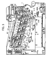
- FIG. 3 is a front view showing the intermediate image transfer belt accommodated in a case and showing the process cartridges 40Y through 40 BK.
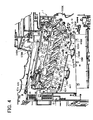
- FIG. 4 is a view showing the apparatus body 1 from which the process cartridges 40Y through 40BK are removed.
- guides 42Y, 42C, 42M and 42BK are affixed to the apparatus body 1 and respectively include support plates 43Y, 43C, 43M and 43BK and stop plates 54Y, 54C, 54M and 54BK, not shown in FIG. 1, rising substantially vertically from the support plates 44Y through 43BK, respectively.
- the support plates 43Y through 43BK respectively guide the bottoms of the process cartridges 40Y through 40BK when the process cartridges are mounted or dismounted to or from the apparatus body 1.
- the support plates 43Y through 43BK each are inclined substantially in parallel to the lower run of the belt 3 which the drums 2Y through 2BK face.
- the support plates 43Y through 43BK each are inclined by 15° relative to a horizontal plane.
- the unit cases 41Y through 40BK of the process cartridges 40Y through 40BK include bottom walls 68Y, 68C, 68M and 68BK, respectively, which are inclined in parallel to the support plates 43Y through 43BK, so that the process cartridges can be mounted to the apparatus body 1 in an inclined position, as stated previously.
- Holes 4Y, 44C, 44M and 44BK and holes 69Y, 69C, 69M and 69 BK are respectively formed in the support plates 43Y through 43BK and the bottle walls 68Y through 68BK of the process cartridges 40Y through 40BK, allowing the laser beams L emitted from the optical writing unit 8 to be incident on the drums 2Y through 2BK.
- the process cartridges 40Y through 40BK each are mounted to the apparatus body 1 in a direction indicated by an arrow E in FIG. 4 and dismounted from the same in a direction indicated by an arrow F.
- the bottom walls 68Y through 68BK of the process cartridges 40Y through 40 BK are respectively guided by the support plates 38Y through 38BK.
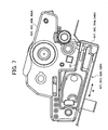
- the side walls of the unit cases 41 through 41BK are respectively abutted against the stop plates 54Y through 54GK due to the weights of the process cartridges, see FIG. 7.
- the process cartridges 40Y through 40 BK are smoothly mounted to or dismounted from the apparatus body 1 by being protected from widthwise shift by the guides 42Y through 42BK, respectively.
- the widthwise direction of each process cartridge refers to a direction W, see FIG. 6, perpendicular to the lengthwise direction LL of the process cartridge.
- the illustrative embodiment is configured such that in the condition wherein the process cartridge 40Y, for example, is set on the apparatus body 1, the holes 44Y and 69Y are positioned at a higher level than the wall portion AR of the case below the cleaning blade or cleaning member 35Y. More specifically, in the illustrative embodiment, the hole 44Y of the case bottom wall 68Y and support plate 43Y each are inclined relative to a horizontal plane, as stated previously. Consequently, the holes 44Y and 69Y are positioned at a higher level than the bottom portion AR of the case below the cleaning blade 35Y.
- the cleaning device 13Y further includes a waste toner screw or toner conveying means 36Y configured to convey the toner removed from the drum 2Y by the cleaning blade or cleaning member 35Y to the outside of the cleaning device 13Y.
- This toner conveying means is positioned below the axis O of the drum or image carrier 2Y, so that the toner is conveyed by the waste toner screw 36Y at a side remote from the drum 2Y and charge roller 7Y. This prevents the toner from being scattered toward the drum 2Y or the charge roller 7Y.
- the other process cartridges 40C, 40M and 40BK are configured in exactly the same manner as the process cartridge 40Y.
- the developing device 9Y also included in the process cartridge 40Y of the illustrative embodiment, is located at opposite side to the cleaning device 13Y with respect to the drum 2Y. Further, as shown in FIG. 2, the developing roller 11Y of the developing device 9Y is rotated in such a direction as to convey the developer D upward at the position where the developing roller 11Y faces the drum 2Y. In addition, the drum 2Y moves in the same direction as the developing roller 11Y at the position where the former faces the latter. This is also true with the other process cartridges 40C, 40M and 40BK. Thus, the developing roller 11Y, conveying the developer upward, prevents the carrier or the toner of the developer from moving into or out of the process cartridge, thereby protecting the inside of the process cartridge and that of the apparatus from smears.
- a plurality of process cartridges are arranged side by side, and each is inclined relative to a horizontal plane, as stated earlier.
- at least part of the cleaning device of the upper process cartridge is positioned above the developing device of the lower process cartridge.
- at least part of the lubricant coating device of the upper process cartridge is positioned above the developing device of the lower process cartridge.
- the cleaning device 13Y and lubricant coating device 63Y of the upper process cartridge 40 are positioned above the developing device 9C of the lower process cartridge 40C.
- an A4 machine can be loaded with a zinc stearate bar sized 8 x 8 x 236 mm that extends the life of the process cartridge to more than 100,000 paper sheets.
- the illustrative embodiment therefore, solves the problem of a conventional image forming apparatus that because a space wide enough to accommodate a large lubricant is not available, a small lubricant should be used and is used up before the lives of the other parts of the process cartridge end. Moreover, the life of the lubricant and the lives of the other parts of the process cartridge are substantially coincident, so that the process cartridge can be replaced without wasteful cost.
- the apparatus body 1 includes guide portions 55Y, 55C, 55M and 55 BK, not shown in FIG. 1 or 2, for restricting the upward movement of the process cartridges.
- the guide portions 55Y through 55BK are formed flat by cutting and raising part of restricting plates 54Y through 54BK, which comprise sheet metal or similar flat materials.
- the guide portions 55Y through 55BK are spaced upward from the support plates 43Y through 43BK, respectively.
- the engaging portion 56 of the process cartridge contacts the underside of associated one of the guide portions 55Y through 55BK, FIGS. 4 and 5. This is also true when the process cartridge is pulled out of the apparatus body 1. Consequently, the process cartridge is prevented from moving upward and causing its drum from contacting the belt 3 when mounted to the process cartridge, thereby protecting the surface of the drum and that of the belt 3 from scratches.
- the guide portions 55Y through 55BK are shorter than the support plates 43Y through 43BK in the front-and-rear direction of the apparatus body 1.
- the engaging portions 56 of the process cartridges 40Y through 40BK get out of the associated guide portions 55Y through 55BK. Therefore, when any one of the process cartridges 40Y through 40BK is inserted into the apparatus body 1 up to a preselected position, it can be shifted upward to bring its drum into contact with the belt 3.
- the guide portions 55Y through 55BK limit the upward movement of the process cartridges 40Y through 40BK, respectively, up to a preselected position in the apparatus body 1.
- bulges 57Y, 57C, 57M and 57BK respectively rise from the rear portions of the support plates 43Y, 43C, 43M and 43BK.
- the engaging portion 56 of the process cartridge gets out of associated one of the guide portions 55Y through 55BK, and then the process cartridge gets on associated one of the bulges 57Y through 57BK and is raised thereby with the result that the drum of the process cartridge is caused to contact the belt 3.
- the process cartridge When any one of the process cartridges 40Y through 40BK is inserted into the apparatus body 1, the process cartridge must be accurately positioned at a preselected position.
- the stop plates 54Y through 54BK are respectively formed with positioning holes 58Y through 58BK in their front portions.
- the process cartridges 40Y through 40BK each are formed with a reference projection or reference portion 59 in its front portion.
- a faceplate may by mounted on the apparatus body 1 and brought to a closed position.
- a pin may be studded on the rear end of each process cartridge and caused to mate with a positioning hole formed in the rear wall of the apparatus body 1, although not shown specifically.
- the process cartridge should advantageously be unlocked from the apparatus body 1 by the following configuration.
- a handle 60 is affixed to the front portion of each of the unit cases 41Y through 41BK.
- the handle 60 is angularly movable between a use position X and a non-use or store position Y in a direction indicated by a double-headed arrow Z.
- FIGS. 6, 7 and 8 show the handle 60 stored in the non-use position.
- the illustrative embodiment is configured to transfer toner images from the drums or image carriers to the belt or image transfer body one above the other.
- the present invention is similarly applicable to an image forming apparatus of the type directly transferring toner images formed on image carriers to a recording medium one above the other. Further, the present invention is applicable even to an image forming apparatus including a single process cartridge.
- the present invention provides an image forming apparatus capable of preventing toner from dropping via a hole assigned to a light beam and smearing an optical writing unit.
Landscapes
- Physics & Mathematics (AREA)
- General Physics & Mathematics (AREA)
- Engineering & Computer Science (AREA)
- Computer Vision & Pattern Recognition (AREA)
- Electrophotography Configuration And Component (AREA)
- Dry Development In Electrophotography (AREA)
- Cleaning In Electrography (AREA)
Applications Claiming Priority (1)
| Application Number | Priority Date | Filing Date | Title |
|---|---|---|---|
| JP2004130412A JP2005315913A (ja) | 2004-04-26 | 2004-04-26 | 画像形成装置 |
Publications (1)
| Publication Number | Publication Date |
|---|---|
| EP1621941A1 true EP1621941A1 (fr) | 2006-02-01 |
Family
ID=34935440
Family Applications (1)
| Application Number | Title | Priority Date | Filing Date |
|---|---|---|---|
| EP05008613A Withdrawn EP1621941A1 (fr) | 2004-04-26 | 2005-04-20 | Appareil de formation des images |
Country Status (4)
| Country | Link |
|---|---|
| US (1) | US7305203B2 (fr) |
| EP (1) | EP1621941A1 (fr) |
| JP (1) | JP2005315913A (fr) |
| CN (1) | CN100394315C (fr) |
Families Citing this family (22)
| Publication number | Priority date | Publication date | Assignee | Title |
|---|---|---|---|---|
| JP4375699B2 (ja) * | 2000-09-14 | 2009-12-02 | 株式会社リコー | タンデム作像装置およびそれを備える画像形成装置、ならびに作像手段の配置方法 |
| JP4755867B2 (ja) | 2004-11-26 | 2011-08-24 | 株式会社リコー | 現像装置、及びこれを備えたプロセスカートリッジ、画像形成装置 |
| JP2006251301A (ja) | 2005-03-10 | 2006-09-21 | Ricoh Co Ltd | 現像装置並びにこれを用いたプロセスカートリッジ及び画像形成装置、トナー |
| JP2007178970A (ja) * | 2005-11-30 | 2007-07-12 | Ricoh Co Ltd | プロセスカートリッジ、画像形成装置 |
| JP4827554B2 (ja) * | 2006-02-27 | 2011-11-30 | 株式会社リコー | 潤滑剤塗布装置、プロセスカートリッジ、及び画像形成装置 |
| JP4764766B2 (ja) * | 2006-05-01 | 2011-09-07 | 株式会社リコー | 現像装置、プロセスカートリッジ及び画像形成装置 |
| JP2008102489A (ja) | 2006-09-19 | 2008-05-01 | Ricoh Co Ltd | 現像剤搬送装置、現像装置、プロセスユニット及び画像形成装置 |
| JP2009047714A (ja) * | 2006-09-19 | 2009-03-05 | Ricoh Co Ltd | 現像剤搬送装置、現像装置、プロセスユニット及び画像形成装置 |
| JP2008102492A (ja) * | 2006-09-19 | 2008-05-01 | Ricoh Co Ltd | 現像剤搬送装置、現像装置、プロセスユニット及び画像形成装置 |
| KR101101822B1 (ko) * | 2007-02-13 | 2012-01-05 | 삼성전자주식회사 | 현상장치 및 이를 채용한 화상형성장치 |
| JP5130035B2 (ja) * | 2007-12-21 | 2013-01-30 | 株式会社リコー | プロセスカートリッジ及び画像形成装置 |
| JP5187114B2 (ja) * | 2008-02-25 | 2013-04-24 | 株式会社リコー | 現像装置、プロセスカートリッジおよび画像形成装置 |
| JP5299686B2 (ja) * | 2008-08-08 | 2013-09-25 | 株式会社リコー | プロセスカートリッジ、及び、画像形成装置 |
| JP5311280B2 (ja) * | 2008-09-10 | 2013-10-09 | 株式会社リコー | 潤滑剤供給装置、プロセスユニット及び画像形成装置 |
| JP4307517B1 (ja) | 2008-12-02 | 2009-08-05 | キヤノン株式会社 | カラー電子写真画像形成装置 |
| JP5724407B2 (ja) * | 2011-01-27 | 2015-05-27 | 株式会社リコー | 潤滑剤供給装置、プロセスカートリッジ、及び、画像形成装置 |
| JP6195149B2 (ja) | 2013-05-14 | 2017-09-13 | 株式会社リコー | 画像形成装置 |
| JP6137615B2 (ja) | 2013-05-21 | 2017-05-31 | 株式会社リコー | 画像形成装置及び画像濃度制御方法 |
| JP2016184043A (ja) * | 2015-03-25 | 2016-10-20 | 富士ゼロックス株式会社 | 現像剤補給装置及び画像形成装置 |
| JP6620978B2 (ja) | 2015-10-22 | 2019-12-18 | 株式会社リコー | 現像装置、画像形成装置およびプロセスカートリッジ |
| US10031441B2 (en) * | 2015-10-26 | 2018-07-24 | Ricoh Company, Ltd. | Developing device, and image forming apparatus and process cartridge incorporating same |
| JP6465067B2 (ja) * | 2016-04-27 | 2019-02-06 | 京セラドキュメントソリューションズ株式会社 | 画像形成装置 |
Citations (9)
| Publication number | Priority date | Publication date | Assignee | Title |
|---|---|---|---|---|
| EP0341667A2 (fr) | 1988-05-09 | 1989-11-15 | Mita Industrial Co., Ltd. | Machine de formation d'images |
| JPH086385A (ja) * | 1994-06-20 | 1996-01-12 | Brother Ind Ltd | 画像形成装置 |
| JPH08202226A (ja) | 1995-01-31 | 1996-08-09 | Ricoh Co Ltd | 画像形成装置 |
| JP2002062711A (ja) | 2000-06-05 | 2002-02-28 | Ricoh Co Ltd | 画像形成装置 |
| JP2003149995A (ja) * | 2001-08-31 | 2003-05-21 | Ricoh Co Ltd | 画像形成装置 |
| EP1331525A2 (fr) | 2002-01-25 | 2003-07-30 | Ricoh Company, Ltd. | Appareil de formation d'images comprenant une qualité d'image et une facilité de maintenance améliorées |
| JP2003316107A (ja) | 2001-09-07 | 2003-11-06 | Ricoh Co Ltd | 画像形成装置、搬送ユニット、中間転写ユニット及びプロセスカートリッジ |
| JP2004077554A (ja) * | 2002-08-09 | 2004-03-11 | Ricoh Co Ltd | 画像形成装置 |
| JP2004117386A (ja) * | 2002-09-20 | 2004-04-15 | Ricoh Co Ltd | カラー画像形成装置 |
Family Cites Families (8)
| Publication number | Priority date | Publication date | Assignee | Title |
|---|---|---|---|---|
| JPS6364068A (ja) * | 1986-09-05 | 1988-03-22 | Ricoh Co Ltd | 静電記録装置 |
| JPH03101757A (ja) | 1989-09-16 | 1991-04-26 | Fujitsu Ltd | 電子写真装置 |
| JP2000075745A (ja) | 1998-08-26 | 2000-03-14 | Canon Inc | クリーニング装置又はプロセスカートリッジ又は画像形成装置 |
| JP2001228774A (ja) | 2000-02-14 | 2001-08-24 | Matsushita Electric Ind Co Ltd | 画像形成装置 |
| US7010246B2 (en) * | 2002-06-10 | 2006-03-07 | Ricoh Company, Ltd. | Image forming apparatus, drum unit, image forming module, and method of insertion and removal of a damper into and from an image carrier drum |
| CN100407065C (zh) * | 2002-12-20 | 2008-07-30 | 株式会社理光 | 图像形成装置 |
| EP1452931A1 (fr) * | 2003-02-28 | 2004-09-01 | Ricoh Company, Ltd. | Appareil de fomation d'image avec cartouche de traitement à installer |
| JP4647232B2 (ja) * | 2003-06-24 | 2011-03-09 | 株式会社リコー | プロセスカートリッジ及び画像形成装置 |
-
2004
- 2004-04-26 JP JP2004130412A patent/JP2005315913A/ja active Pending
-
2005
- 2005-04-15 US US11/106,435 patent/US7305203B2/en not_active Expired - Lifetime
- 2005-04-20 EP EP05008613A patent/EP1621941A1/fr not_active Withdrawn
- 2005-04-26 CN CNB2005100669933A patent/CN100394315C/zh not_active Expired - Fee Related
Patent Citations (9)
| Publication number | Priority date | Publication date | Assignee | Title |
|---|---|---|---|---|
| EP0341667A2 (fr) | 1988-05-09 | 1989-11-15 | Mita Industrial Co., Ltd. | Machine de formation d'images |
| JPH086385A (ja) * | 1994-06-20 | 1996-01-12 | Brother Ind Ltd | 画像形成装置 |
| JPH08202226A (ja) | 1995-01-31 | 1996-08-09 | Ricoh Co Ltd | 画像形成装置 |
| JP2002062711A (ja) | 2000-06-05 | 2002-02-28 | Ricoh Co Ltd | 画像形成装置 |
| JP2003149995A (ja) * | 2001-08-31 | 2003-05-21 | Ricoh Co Ltd | 画像形成装置 |
| JP2003316107A (ja) | 2001-09-07 | 2003-11-06 | Ricoh Co Ltd | 画像形成装置、搬送ユニット、中間転写ユニット及びプロセスカートリッジ |
| EP1331525A2 (fr) | 2002-01-25 | 2003-07-30 | Ricoh Company, Ltd. | Appareil de formation d'images comprenant une qualité d'image et une facilité de maintenance améliorées |
| JP2004077554A (ja) * | 2002-08-09 | 2004-03-11 | Ricoh Co Ltd | 画像形成装置 |
| JP2004117386A (ja) * | 2002-09-20 | 2004-04-15 | Ricoh Co Ltd | カラー画像形成装置 |
Non-Patent Citations (3)
| Title |
|---|
| PATENT ABSTRACTS OF JAPAN vol. 1996, no. 12 26 December 1996 (1996-12-26) * |
| PATENT ABSTRACTS OF JAPAN vol. 2002, no. 06 4 June 2002 (2002-06-04) * |
| PATENT ABSTRACTS OF JAPAN vol. 2003, no. 12 5 December 2003 (2003-12-05) * |
Also Published As
| Publication number | Publication date |
|---|---|
| CN100394315C (zh) | 2008-06-11 |
| US20050238384A1 (en) | 2005-10-27 |
| US7305203B2 (en) | 2007-12-04 |
| CN1690876A (zh) | 2005-11-02 |
| JP2005315913A (ja) | 2005-11-10 |
Similar Documents
| Publication | Publication Date | Title |
|---|---|---|
| EP1621941A1 (fr) | Appareil de formation des images | |
| JP4720900B2 (ja) | 感光体ユニットおよび画像形成装置 | |
| JP4710965B2 (ja) | 画像形成装置および感光体ユニット | |
| US8509650B2 (en) | Electrophotographic image forming apparatus | |
| US7415223B2 (en) | Image formation apparatus and photoreceptor cartridge | |
| JP4586726B2 (ja) | 画像形成装置 | |
| US8406657B2 (en) | Color electrophotographic image forming apparatus | |
| US8467701B2 (en) | Color electrophotographic image forming apparatus | |
| JP4332806B2 (ja) | 現像ユニットおよび画像形成装置 | |
| JP4384251B1 (ja) | 現像カートリッジ、プロセスカートリッジ、及び電子写真画像形成装置 | |
| US8073360B2 (en) | Color electrophotographic image forming apparatus | |
| US7796916B2 (en) | Image forming apparatus having a guide for guiding at first and/ or second image forming units to be mounting in the apparatus when an openable member is open | |
| JP2007322554A (ja) | 感光体ユニットおよび画像形成装置 | |
| JP2010055114A (ja) | 画像形成装置 | |
| KR20050003876A (ko) | 전자사진방식 인쇄기 | |
| US7483648B2 (en) | Process cartridge and image forming apparatus using the same | |
| JP4687535B2 (ja) | 画像形成装置 | |
| JP4653401B2 (ja) | プロセスカートリッジおよび画像形成装置 | |
| US5923926A (en) | Developing device and electrophotographic image forming apparatus | |
| JP2006276775A (ja) | 画像形成装置 | |
| JP2004279551A (ja) | 画像形成装置 | |
| JP2012163845A (ja) | プロセスカートリッジ及び電子写真画像形成装置 | |
| JP2010211176A (ja) | 現像カートリッジ、プロセスカートリッジ、及び電子写真画像形成装置 | |
| HK1009513A1 (en) | Developing device and electrophotographic image forming apparatus | |
| HK1009513B (en) | Developing device and electrophotographic image forming apparatus |
Legal Events
| Date | Code | Title | Description |
|---|---|---|---|
| PUAI | Public reference made under article 153(3) epc to a published international application that has entered the european phase |
Free format text: ORIGINAL CODE: 0009012 |
|
| 17P | Request for examination filed |
Effective date: 20050420 |
|
| AK | Designated contracting states |
Kind code of ref document: A1 Designated state(s): AT BE BG CH CY CZ DE DK EE ES FI FR GB GR HU IE IS IT LI LT LU MC NL PL PT RO SE SI SK TR |
|
| AX | Request for extension of the european patent |
Extension state: AL BA HR LV MK YU |
|
| AKX | Designation fees paid |
Designated state(s): DE ES FR GB IT NL |
|
| 17Q | First examination report despatched |
Effective date: 20100805 |
|
| STAA | Information on the status of an ep patent application or granted ep patent |
Free format text: STATUS: THE APPLICATION IS DEEMED TO BE WITHDRAWN |
|
| 18D | Application deemed to be withdrawn |
Effective date: 20150310 |