EP1622005B1 - Gerät und Verfahren zur Steuerung eines Verzweigungsbefehls anhand einer Verzweigungsreservationsstelle - Google Patents
Gerät und Verfahren zur Steuerung eines Verzweigungsbefehls anhand einer Verzweigungsreservationsstelle Download PDFInfo
- Publication number
- EP1622005B1 EP1622005B1 EP04257346A EP04257346A EP1622005B1 EP 1622005 B1 EP1622005 B1 EP 1622005B1 EP 04257346 A EP04257346 A EP 04257346A EP 04257346 A EP04257346 A EP 04257346A EP 1622005 B1 EP1622005 B1 EP 1622005B1
- Authority
- EP
- European Patent Office
- Prior art keywords
- entries
- branch
- entry
- instruction
- branch instruction
- Prior art date
- Legal status (The legal status is an assumption and is not a legal conclusion. Google has not performed a legal analysis and makes no representation as to the accuracy of the status listed.)
- Expired - Lifetime
Links
Images








Classifications
-
- G—PHYSICS
- G06—COMPUTING OR CALCULATING; COUNTING
- G06F—ELECTRIC DIGITAL DATA PROCESSING
- G06F9/00—Arrangements for program control, e.g. control units
- G06F9/06—Arrangements for program control, e.g. control units using stored programs, i.e. using an internal store of processing equipment to receive or retain programs
- G06F9/30—Arrangements for executing machine instructions, e.g. instruction decode
- G06F9/38—Concurrent instruction execution, e.g. pipeline or look ahead
- G06F9/3861—Recovery, e.g. branch miss-prediction, exception handling
-
- G—PHYSICS
- G06—COMPUTING OR CALCULATING; COUNTING
- G06F—ELECTRIC DIGITAL DATA PROCESSING
- G06F9/00—Arrangements for program control, e.g. control units
- G06F9/06—Arrangements for program control, e.g. control units using stored programs, i.e. using an internal store of processing equipment to receive or retain programs
- G06F9/30—Arrangements for executing machine instructions, e.g. instruction decode
- G06F9/38—Concurrent instruction execution, e.g. pipeline or look ahead
- G06F9/3802—Instruction prefetching
- G06F9/3804—Instruction prefetching for branches, e.g. hedging, branch folding
-
- G—PHYSICS
- G06—COMPUTING OR CALCULATING; COUNTING
- G06F—ELECTRIC DIGITAL DATA PROCESSING
- G06F9/00—Arrangements for program control, e.g. control units
- G06F9/06—Arrangements for program control, e.g. control units using stored programs, i.e. using an internal store of processing equipment to receive or retain programs
- G06F9/30—Arrangements for executing machine instructions, e.g. instruction decode
- G06F9/38—Concurrent instruction execution, e.g. pipeline or look ahead
- G06F9/3802—Instruction prefetching
- G06F9/3814—Implementation provisions of instruction buffers, e.g. prefetch buffer; banks
-
- G—PHYSICS
- G06—COMPUTING OR CALCULATING; COUNTING
- G06F—ELECTRIC DIGITAL DATA PROCESSING
- G06F9/00—Arrangements for program control, e.g. control units
- G06F9/06—Arrangements for program control, e.g. control units using stored programs, i.e. using an internal store of processing equipment to receive or retain programs
- G06F9/30—Arrangements for executing machine instructions, e.g. instruction decode
- G06F9/38—Concurrent instruction execution, e.g. pipeline or look ahead
- G06F9/3836—Instruction issuing, e.g. dynamic instruction scheduling or out of order instruction execution
Definitions
- the present invention relates to an instruction control method in a computer system, and more specifically to a branch instruction control apparatus and a control method in which new entries are made and a flag required for the control of a branch instruction is updated in accordance with the release of entries as an entry control method for a branch reservation station for controlling a branch instruction, and entries are rearranged by a bubble-up mechanism, in a computer in which an out-of-order method is adopted.
- an instruction which has been inputted to an implementation pipeline in advance sometimes affects the implementation of succeeding instructions.
- the succeeding instructions are implemented based on the implementation results of the preceding instruction, if the processing of the preceding instruction is delayed, no succeeding instructions can be implemented during that time, and the succeeding instructions must keep waiting for the completion of the preceding instruction. In this way, a branch instruction in particular, among instructions which affect the implementation of succeeding instructions, greatly affects the succeeding instructions.
- the preceding instruction which has been implemented in advance is an instruction which is going to change branch conditions, unless the implementation results of that instruction are not fixed, it is not possible to judge whether a branch exists or not. If it is not possible to judge whether a branch exists or not, the sequence of the succeeding instructions of the branch instruction cannot be established.
- an instruction control apparatus which adopts any other processing method, and is the problem common to any instruction control apparatus.
- an instruction control apparatus holds a branch prediction mechanism. By predicting a branch, it is possible to input the succeeding instruction sequences of the branch instruction one after another to the implementation pipeline without waiting for the completion of the branch instruction.
- a plurality of branch instructions are inputted to the implementation pipeline based on branch prediction results.
- the branch instructions which are inputted to the implementation pipeline are controlled in a branch instruction control unit.
- the branch instruction control unit can control a plurality of branch instructions, but there is an upper limit in the number of branch instructions which can be controlled at a time. If the processing of branch instructions is delayed, the resources of the branch instruction control unit decrease gradually, and when the number of branch instructions which are inputted to the implementation pipeline reach the upper limit of the number of entries which can be processed at the same time, no new instruction can be inputted to the pipeline any more.
- a reservation station When the instruction control apparatus is controlled by the out-of-order method, all the instructions are controlled by the instruction control unit called a reservation station.
- a pointer method or a bubble-up method is a general method for controlling entries of a reservation station. When entries are controlled by the pointer method, it is possible to effectively use the number of entries which are limited resources without waste, but there is a demerit in that the pointer method cannot easily cope with the tendency of high frequencies used in instruction control apparatuses in recent years.
- Each entry of the reservation station is controlled by a VALID signal indicating that the entry is valid or invalid.
- the VALID signal is 0 (zero) and the entries are invalid, succeeding instructions could not use the entries in prior art. Consequently, until the entries are released (reset) and the succeeding instructions can come to use the entries, the entries are toothless temporarily, and useless cycles in which part of entries cannot be used are generated.
- entries When an branch instruction is controlled by a reservation station, entries must be released in order. Therefore, the entries in the reservation station must always line up in the order of instructions.
- the entries of a branch reservation station are controlled by the bubble-up method, if the entries become toothless temporarily after the entries are released and the entries cannot be used effectively, the entries reach the seeming upper limit of the number of entries, so no new instruction can be inputted to the implementation pipeline.
- the throughput of the branch instruction decreases, thus causing the performance of an instruction control apparatus to be decreased.
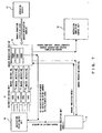
- Fig. 1 is an example showing the release of entries in a branch reservation station and the process of making a new entry in accordance with the input of a new instruction in prior art.
- a total of ten entries, for example, from RSBR0 to RSBR9 are provided in the branch reservation station.
- data or flags required for the control of branch instruction 1 to branch instruction 6 are stored for six entries from RSBR0 to RSBR5; branch instruction 7 and branch instruction 8 are going to be inputted to RSBR6 and RSBR7 respectively from the side of the decoder; and the control is going to be completed for branch instruction 1 to branch instruction 3.
- bubbling-up is carriedout, and the contents of each entry are moved in a direction toward the top entry.
- this bubbling-up is carried out after the entry positioned in a direction toward the top entry is released and the VALID flag for the released entry is lowered. Consequently, the bubbling-up is carried out after it is confirmed that the entries from RSBR0 to RSBR2 have been released and the VALID flag has been lowered.
- RSBR0, RSBR1 and RSBR7 out of ten entries are empty, that is to say, toothless. So, when trying to input new branch instructions from the side of the decoder in this cycle, there is no empty entry on the rear end side of the branch reservation station, and no new branch instruction can be inputted in the implementation pipeline.
- Fig. 2 to Fig. 5 show part of the control circuit corresponding to a conventional technology of FIG.1 .
- the control circuits of the present invention which will be explained later, described below is the operation of these control circuits (shown in Fig. 2 to Fig.5 ).
- Fig. 2 shows a bubble-up control signal output circuit (No. 1).
- all the entries from RSBR0 which is the top entry to RSBRm which is the (m+1) th entry exist in the branch reservation station.
- a disabled bubble-up signal indicating bubble-up inability is outputted from the buffer 100.
- bubbling-up is carried out in the form in which the contents of an entry are moved in a direction toward the top entry by the number of one entry for each of the entries, so bubbling-up is impossible when data is stored continuously in all the entries from the top entry to the (m+1)th entry.
- Fig. 3 shows a bubble-up control signal output circuit (No. 2).
- an enable_lup signal indicating that the bubbling-up of the entry following the empty entry is possible is outputted from the buffer 101.
- Fig. 4 shows the output circuit of a load permitting (enabling) signal for data for RSBRm from the decoder.
- a VALID signal indicating that RSBR (m-1) is valid for the AND gate 102
- a signal indicating that entries from RSBRm to RSBRn which is the last entry do not exist, that is to say, these entries are empty are inputted, loading of data such as a flag in the entry RSBRm is permitted from the decoder.
- Fig. 5 shows the latch circuit holding data such as a flag required for the control of branch instructions as the entry of the branch reservation station.
- Fig. 5 corresponds to the RSBR0 of the top entry , and in the prior art shown in Fig. 1 , the same type latch circuit as shown in Fig. 5 is used in correspondence with the three entries from the top entry to RSBR2.
- a set signal which sets data such as a flag to the entry of RSBR0 is given to the set terminal.
- a COMPLETE signal indicating that the branch instruction for the entry of RSBR0 via the OR gate 104 has been completed a CLEAR signal which releases the entry of RSBR0 when re-instruction fetching is required as will be described later, and RS1 as a RESET signal used for interrupt, etc. are inputted to a reset terminal, and when these signals become H (1), a reset is executed.
- the COMPLETE signal of RSBR0 resets the contents of the latch 103, but basically, it is used to lower the VALID flag in order to carry out bubbling-up as described above.
- the difference lies only in that only a COMPLETE signal as the entry of the OR gate 104 is excluded. This is because in prior art of FIG. 1 , when the control of branch instructions is completed, the entries which are released are limited to three entries from RSBR0 to RSBR2, and entries which are released at the same time are limited to one or more entries which can be released continuously from the top entry.
- Patent document 1 Kokai (Jpn. unexamined patent publication) No. 2000-181707 "Instruction Control Apparatus and Method"
- an instruction control apparatus in which a reservation station in which a plurality of instructions which have been decoded and which have not been issued to the implementation unit are stored temporarily is provided, and in which information stored in entries is moved by the bubble-up method for the reservation station.
- the problem was not solved in that entries become toothless with the operation method in which bubbling-up is carried out after the VALID flags of the entries which have been released are lowered as described in Fig. 1 .
- US2004003214 discloses an instruction control method which uses delay instructions for branching, and successively stores a plurality of delay instructions in a storage unit together with information indicating whether or not the branch instructions corresponding to the delay instructions are predicted to branch.
- US2001 004756 discloses an apparatus which stores data corresponding to each type of instruction, and includes: an information reservation station unit for performing integral control containing a resource updating process performed when the instruction is completely executed. It also includes one or more function reservation station units for storing data corresponding to the function relating to the execution of the instruction and controlling the execution of the function under the integral control of the instruction reservation station unit.
- US3718912 discloses an execution system for instructions having source and sink operand designations which includes an arithmetic unit, execution means for holding an instruction for controlling the arithmetic unit and a plurality of operand registers, each having tag means associated therewith for indicating the nature of data stored therein.
- Instruction modification logic on the basis of indications of availability of the operand registers, inserts modified source and sink operand register designations in instructions which are then stored in an instruction register stack.
- Interlock logic controls the transfer of instructions from the instruction register stack to the execution means as a function of the source and sink operand register designations in the modified instructions and the data tags associated with the operand registers.
- a branch instruction control apparatus having a plurality of entries, each entry being arranged to store data required for the implementation control of a corresponding branch instruction and a valid flag of the data in order of decoding successively from a top entry, comprising: a bubble-up mechanism, when one or more entries are successively released in order of older decoding from the top entry among entries whose implementation control of the corresponding branch instructions has been completed, for moving the contents of remaining entries in a direction toward the top entry by number of released entries regardless of the valid flag of the released entries, and a new-entry data set unit for storing data required for the implementation control of newly decoded branch instructions in one or more empty entries which are near the top entry including entries which become empty by the movement, in the same cycle as in the movement of the said contents of remaining entries by the bubble-up mechanism.
- a branch instruction control method for controlling branch instructions using a plurality of entries, in which each entry stores data required for the implementation control of a corresponding branch instruction each entry being stores in order of decoding successively from a top entry, wherein when one or more entries are successively released in order of older decoding from the top entry among entries whose implementation control of the corresponding branch instructions has been completed, contents of remaining entries are moved in a direction toward the top entry by number of released entries regardless of the valid flag of the released entries by a bubble-up mechanism; and data required for the implementation control of newly decoded branch instructions is stored in one or more empty entries which are near the top entry including entries which become empty by the movement, in the same cycle as in the movement of the said contents.
- the present invention has been developed to improve the throughput of branch instructions and prevent the performance of the instruction control apparatus from decreasing by preventing a temporary toothless state after entries are released when the entries of branch reservation stations are controlled by the bubble-up method.
- the branch instruction control apparatus of the present invention is a control apparatus in which a plurality of entries in which data required for the implementation control of the branch instructions is stored in order of decoding successively from the top entry are provided, and said apparatus comprises a mechanism which, when one or more entries are successively released in order of older decoding from the top entry among the entries whose implementation control of the corresponding branch instruction has been completed, moves the contents of the remaining entries in a direction toward the top entry by the number of entries released, and a unit for storing data required for the implementation control of newbranch instructions in one or more empty entries which are near the top entry including the entries which become empty by the movement, in the same cycle as in the movement of the said contents.
- Fig. 6 is a block diagram showing the configuration of the principle of the branch instruction control apparatus of the present invention.
- Fig. 6 is a block diagram showing the configuration of the principle of the branch instruction control apparatus 1 which includes a plurality of entries 2 in which data required for the implementation control of branch instructions is stored in order of the decoding of the branch instructions successively from the top entry in accordance with each branch instruction, and the apparatus 1 comprises a bubble-up mechanism 3 and a new-entry data set unit 4.
- the bubble-up mechanism 3 is the mechanism which, when one or more entries are successively released in order of older decoding from the top entry among the entries whose implementation control of the branch instructions has been completed, moves the contents of the remaining entries in a direction toward the top entry by the number of entries released, and the new-entry data set unit 4 sets data required for the implementation control of newly decoded branch instructions in one or more empty entries which are near the top entry including the entries which become empty by the movement, in the same cycle as the movement of the said contents.
- the number of entries released and the number of new entries in which data is newly set can be made equal, and it is possible to further include an entry data update unit (for example, a RSBR update circuit) for updating data required for the implementation control of branch instructions stored in each entry in the same cycle as the movement of the contents of entries by the bubble-up mechanism 3.
- an entry data update unit for example, a RSBR update circuit
- an entry release unit (used when re-instructions are fetched) which, when the branch prediction concerning the branch instructions corresponding to the entries in which data required for the implementation control of branch instructions is stored ends in failure and re-instructions are fetched in the same cycle as in the movement of the contents of entries by the bubble-up mechanism 3, releases the entries corresponding to new branch instructions in which the order of decoding is newer than that of the branch instructions including the entries before being bubbled-up which correspond to the branch instructions.
- an entry release unit used when re-instructions are fetched
- the branch instruction control method of the present invention is a method which controls branch instructions using a plurality of entries in which data required for the implementation control of the branch instructions is stored in the order of decoding of the branch instructions successively from the top entry in accordance with the branch instructions, and the method which, when one or more entries are successively released in the order of older decoding from the top entry among the entries whose implementation control of the corresponding branch instruction has been completed, the bubble-up mechanism moves the contents of the remaining entries in a direction toward the top entry by the number of entries released, and sets data required for the implementation control of the branch instructions which are newly decoded to one or more empty entries which are near the top entry including the entries which become empty by the movement, in the same cycle as the movement of said contents.
- the entries which are waiting for implementation can be rearranged by the bubble-up mechanism; new entries corresponding to new branch instructions can be made; flags required for the branch instruction control can be updated; the throughput of instruction processing control equivalent to the entry control by the pointer method can be realized; and can easily cope with the change of the frequency of the instruction control apparatus into high frequency, thus contributing greatly to increasing the performance of the information processing system.
- Fig. 7 is a block diagram showing the whole configuration of the information processing device in which the branch instruction control apparatus of the present invention, for example, the branch reservation station, is used.
- the information processing device comprises an instruction fetch control unit 10, an instruction decode unit 11, a branch reservation station 12, an operation circuit 13, an instruction completion control unit 14, and a branch prediction unit 15, to process instructions in out-of-order.
- a branch prediction is conducted by the branch prediction unit (branch history) 15 based on a instruction fetch address, and when the instruction is predicted to branch, a branch prediction address is given to the instruction fetch control unit 10. Then, the instruction and the prediction result are inputted to the instruction decode unit 11, and when the instruction is decoded, the instruction is judged to be a branch instruction or an instruction which is predicted to branch, and is inputted to the branch reservation station (reservation station for branch, RSBR) 12, and at the same time, is also given to the instruction completion control unit 14 to which all the instructions are given.
- the RSBR is supposed to include everything, namely a plurality of entries in which data and flags required for the control of branch instruction are stored, a control circuit which carries out various controls such as storing, updating and bubbling-up of data for each entry, etc.
- a condition code as a branch condition and a branch destination address are given to the branch reservation station 12, and from the branch prediction unit 15, a branch prediction result is given to the branch reservation station 12.
- a branch instruction completion report indicating that the control of branch instructions has been completed, or a COMPLETE signal is given to the branch completion control unit 14, and branch prediction update data is given to the branch prediction unit 15 when necessary, and when the branch prediction ends in failure and re-instruction fetching is conducted, the re-instruction fetch request and the re-instruction fetch address are given to the instruction fetch control unit 10.
- the branch reservation station 12 has a plurality of entries, RSBR0, RSBR1, RSBR2 ⁇ to control a plurality of branch instructions at the same time, and when there is any empty entry, a new entry is made in a decoding cycle according to the instructions from the instruction decode unit 11. However, when there is no empty entry, that fact is notified to the branch decode unit 11, and the decoding of all the instructions is stopped.
- the branch reservation station 12 can control n+1 entries from RSBR0 to RSBRn, and can make entries which correspond to a maximum of, for example, two instructions at the same time, and can release entries which correspond to a maximum of two instructions at the same time.
- entries which are released from the RSBR exist.
- the fact that entries are released means that the implementation control of the branch instructions responding to the entries has been completed.
- the RSBR removes the entries whose control has been completed, and continues to control the entries in which the control is continuously required.
- RSBR entries are conducted in order, and since entries are always rearranged in order of decoding of instructions by bubbling-up, each entry is arranged in order of an older instruction from RSBR0.
- RSBR0 is released from the RSBR
- the entry of and after RSBR1 is bubbled up in a direction toward a smaller number by one entry. Since the entry of and after RSBR4 after bubbling-up becomes empty, a new entry is made to RSBR4, or RSBR4 and RSBR5.
- condition 3 since the decoder supplies the instruction sequence which, if fact, cannot be implemented to the pipeline, no new entry is made within the RSBR. However, the instructions prior to the instruction which have been registered and which requests re-instruction fetching are continuously controlled within the RSBR. So, every time an entry is released from the RSBR, bubbling-up is only conducted. If the condition 4) is satisfied, all the entries within the RSBR are deleted. Consequently, no new entry is made.
- Bubbling-up is possible by the number of entries released from the RSBR.
- a maximum of two entries are released at the same time, and in this case, bubbling-up is conducted by the number of two entries.
- the RSBR can be released only from RSBR0 and RSBR1.
- each entry can independently update the flag (data) which the entry holds. Therefore, the control concerning branch instructions becomes possible even during bubbling-up.
- the control concerning branch instructions means the judgement of branch, acquisition of a branch-destination address, judgement of branch prediction, and request of re-instruction fetching when the branch prediction fails.
- the fact that the control concerning branch instructions is possible even during bubbling-up means that as the result of conducting a branch prediction judgement, for example, in RSBR2, if the branch prediction is supposed to end in failure, the request of re-instruction fetching must be issued from RSBR2 to the instruction fetch control unit 10. At that time, RSBR0 is supposed to have satisfied the release condition (COMPLETE condition) from the RSBR in the same cycle. The branch instruction of RSBR2 must stay in RSBR1 in the next cycle as the bubble-up condition is satisfied.
- RSBR2 while issuing the request of re-instruction fetching to the instruction fetch control unit 10, sets data and flags to RSBR1, and issues a reset instruction to the entries of and after RSBR2 in order to clear all the branch instructions existing in and after RSBR3 and all the instructions which have been newly decoded. Furthermore, since the request of re-instruction fetching is issued from RSBR2 to RSBR 1 during bubbling-up, a flag indicating that the request of re-instruction fetching has been issued is set to RSBR1.
- Fig. 8 shows the control circuit of each entry in the branch reservation station 12.
- Each entry has a storage region 21 of a VALID flag indicating whether the entry is valid or not and a storage region 20 of the other flags and data.
- the flags and data stored in the region other then the storage region for the VALID flag are, for example, the branch judgement flag indicating that the branch has been fixed/not fixed, or established/not established, etc., the address of a branch instruction, the address of a branch destination which is given by the operation circuit 13 in Fig. 7 , etc.
- an entry update unit for updating the storage contents of the flags and data for the corresponding entry.
- a RSBR0 update circuit 22 0 for updating the storage contents of the flags and data for RSBR0 is connected to entry RSBR0.
- a selector 23 which selects, for example, data which is inputted from four instruction word registers (IWR) within the instruction decode unit 11 when the instructions are decoded, and the data which is used to move the data of the following entries when entries are bubbled up is provided, and on the right side of the entries, a selector 24 which selects data from the update circuit corresponding to each following entry is provided.
- IWR instruction word registers
- Fig. 8 only the control circuit for the top entry i.e. RSBR0 is shown, but an equivalent control circuit also exists for RSBR1, RSBR2 ⁇ .
- the branch instruction from IWRO and IWR1 among branch instructions which are given to, for example, the selector 23 is inputted to the selector 23 through one path. This is because there is a low possibility that two successive instructions among the four instructions which are decoded at the same time by the instruction decode unit 11 are both branch instructions.
- Fig. 9 shows the BUBBLE-UP control signal output circuit (No. 1).
- Fig. 9 shows the circuit which outputs a bubble-up prohibition signal, i.e. a disable bubble-up signal in the same way as in Fig. 2 in prior art, and this circuit outputs a bubble-up prohibition signal when a COMPLETE signal is L (0) for RSBR0 given to the AND gate 25, and the signal indicting that the entry is VALID is H (1).
- a COMPLETE signal is L (0) for RSBR0 given to the AND gate 25, and the signal indicting that the entry is VALID is H (1).
- Fig. 10 shows the BUBBLE-UP control signal output circuit (No. 2) .
- an ENABLE_1 up signal which moves the contents of each entry by the number of one entry in a direction toward the top entry is outputted from the AND gate 26 when the COMPLETE signal indicating that the implementation control of the branch instruction responding to RSBR0 has been completed is H, and the signal indicating that the implementation control of the branch instruction corresponding to the following entry RSBR1 has been completed is L, that is to say, when the implementation control has not been completed.
- Fig. 11 shows the BUBBLE-UP control signal output circuit (No. 3).
- the buffer 27 outputs an ENABLE_2 up signal which moves the contents of each entry in a direction toward the top entry by the number of tow entries when the COMPLETE signal indicating that the implementation control of the branch instruction corresponding to RSBR1 has been completed is H.
- RSBR1 is the second entry from the top entry; to release entries one after another from the top entry is a basic principle in the control of the branch reservation station 12; when RSBR1 may be released, the COMPLETE signal for RSBR0 is also H; and RSBR0 is also released at the same time. Consequently, the bubbling-up which moves the contents of the respective entries in a direction toward the top entry by the number of two entries is conducted.
- any of the bubble-up control signal output circuits shown in Fig. 9 , Fig. 10 , and Fig. 11 constitutes the mechanism which moves the contents of the remaining entries in a direction toward the top entry by the number of entries released when one or more entries are successively released in the order of older decoding from the top entry among the entries whose implementation control of the corresponding branch instruction has been completed, namely the bubble-up mechanism.
- Fig. 12 shows the ENABLE signal output circuit for data loading from the instruction decode unit 11 for RSBRm.
- the OR gate 33 outputs an ENABLE signal which permits the loading of data for RSBRm from the instruction decode unit 11 when any output of the three AND gates, 30, 31 and 32 becomes H.
- the AND gate 30 outputs H to the OR gate 33 when a disable bubble-up signal as the output of the AND gate 25 shown in Fig. 9 , a VALID signal indicating that the RSBR (m-1), that is, the immediately prior entry is valid, and a signal indicating that entries from RSBRm to RSBRn (i.e. the last entry) do not exist, that is to say, these entries are empty, are inputted as H respectively.
- bubbling-up is not conducted, and the immediately prior entry RSBR (m-1) is valid, and since the entries from RSBRm to the last entry RSBRn are empty, loading of data from the instruction decode unit 11 is permitted.
- Fig. 13 shows the data/flag SET signal output circuit for RSBRm to set data for the latch circuit ( Fig. 14 ) similar to the latch circuit in prior art shown in Fig. 5 .
- the OR gate 36 when the output of the AND gate 35 or the OR gate 40 is H, the OR gate 36 outputs a data SET signal to the latch circuit.
- the OR gate 40 gives the output H to the OR gate 36.
- the AND gate 37 outputs H to the OR gate 40. In other words, bubbling-up is not conducted in this state, the contents of RSBRm as they are are written to the same entry as a self loop again.
- the AND gate 38 gives the output H to the OR gate 40.
- the AND gate 39 gives the output H to the OR gate 40.
- the AND gate 38 writes the contents of RSBR (m+1) to RSBRm when bubbling-up is conducted by the number of one entry
- the AND gate 39 writes the contents of RSBR (m+2) to RSBRm when bubbling-up is conducted by the number of two entries.
- the data SET signal output circuit shown in Fig. 13 together with the data load ENABLE signal output circuit shown in Fig. 12 constitutes the new entry data set unit (corresponding to the AND gate 35) and the bubble-up mechanism, both specified in claim 1.
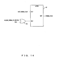
- Fig. 14 shows the latch circuit of each entry corresponding to the latch circuit in prior art shown in Fig. 5 .
- the output of the OR gate 36 shown in Fig. 13 is given to the set terminal of the latch 42, and the output of the OR gate 43 is given to the reset terminal.
- the OR gate 43 When either a CLEAR signal indicating that the release of RSBRmbecomes necessary due to re-instruction fetching or RS1 as a RESET signal unrelated to this embodiment, for example, interrupt is inputted as H, the OR gate 43 outputs H to the set terminal.
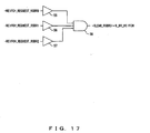
- Each of Fig. 15 to Fig. 17 shows the CLEAR signal output circuit which outputs a CLEAR signal for the corresponding entry when the prediction for the branch instruction fails and re-instruction fetching is performed.
- the request of re-instruction fetching is supposed to be given to the instruction control unit 10 from the branch instruction corresponding to any of these entries.
- the circuits in Fig. 15 to Fig. 17 operate basically in negative logic.
- Fig. 15 shows the CLEAR signal output circuit which resets the second entry RSBR1 from the top.
- a signal indicating that the request of re-instruction fetching to the buffer 45 has been outputted from the branch instruction corresponding to RSBR0 is inputted as L
- a COMPLETE signal for the top entry RSBR0 and a signal indicating that the request of re-instruction fetching to the NAND gate 46 has been outputted from the branch instruction corresponding to the next entry RSBR2 are inputted as H
- a COMPLETE signal for RSBR1 and a signal indicating that the request of re-instruction fetching to the NAND gate 47 has been outputted from the branch instruction corresponding to RSBR2 are inputted as H
- a CLEAR signal for RSBR1 is outputted as L from the AND gate 48.
- the input condition for the NAND gate 46 indicates that though the request of re-instruction fetching is outputted from the branch instruction responding to RSBR1, since the storage contents of RSBR1 are moved to RSBR0 by bubbling-up, RSBR1 should be reset.
- the input condition for the NAND gate 47 indicates that since both RSBR0 and RSBR1 become empty, bubbling-up is conducted by the number of two entries, and the storage contents of RSBR2 are moved to RSBR0, RSBR1 should be reset.
- Fig. 16 shows the CLEAR signal output circuit for RSBR2.
- a CLEAR signal for RSBR2 is outputted via the buffer 50 to which a signal indicating that the request of re-instruction fetching has been outputted from the branch instruction corresponding to RSBR0 is inputted as L; the buffer 51 to which a signal indicating that the request of re-instruction fetching has been outputted from the branch instruction corresponding to RSBR1 is inputted as L; the NAND gate 52 to which a COMPLETE signal for RSBR0 and a signal indicating that the request of re-instruction fetching has been outputted from the branch instruction corresponding to RSBR2 are inputted as H; and the AND gate 53.
- the input condition for the NAND gate 52 indicates that since the top entry is released, bubbling-up is conducted by the number of one entry, and the storage contents of RSBR2 are moved to RSBR1, RSBR2 must be cleared.
- a signal indicating that the request of re-instruction fetching has been outputted from the branch instruction corresponding to either RSBR0, RSBR1 or RSBR2 is inputted as L to the buffer 55, 56 and 57, the remaining entries, RSBR3 to RSBRn, must be released, and a CLEAR signal for these entries is outputted from the AND gate 58.
- any of the entry CLEAR signal output circuits shown in Fig. 15 , Fig. 16 and Fig. 17 constitutes, when the branch prediction concerning the branch instructions corresponding to the entries in which data required for the implementation control of the branch instructions is stored ends in failure, and re-instruction fetching is conducted in the same cycle as in the movement of the contents of entries by the bubble-up mechanism, a unit for releasing the entries corresponding to all the branch instructions in which the order of decoding is newer than said branch instructions, namely an entry release unit when re-instruction fetching is conducted.
- Fig. 18 and Fig. 19 show the branch judgement circuit and the branch-destination address judgement circuit as part of the update circuit corresponding to each entry described in Fig. 8 .
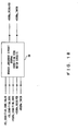
- Fig. 18 shows the operation of the branch judgement circuit (condition code match circuit) for entry RSBRm.
- an EU_CONDITION_CODE_VALID signal indicating that an operation in the operation circuit 13 shown in Fig.
- an EU_CONDITION_CODE signal as the result of the operation a condition code in the OPC of the branch instruction entered to RSBRm, a RESOLVED signal which becomes 1 when branch judgement is completed, and a TAKEN signal which becomes 1 when the establishment of branch has been fixed are inputted to the branch judgment circuit 60, and when a RESOLVED signal indicating that the branch judgment is completed is 0, the branch judgment circuit 60 conducts the branch determination by matching the condition code given from the operation circuit 13 with the condition code entered, and when the RESOLVED signal is 1, the branch judgment circuit 60 carries out the operation of outputting two signals as they are.
- the circuits shown in Fig. 18 and Fig. 19 exist between, for example, the OR gate shown in Fig. 13 and the set terminal of the latch circuit 42 shown in Fig. 14 , and are used to update part of flags and data.
- the flags and data which are updated by the update circuit 22 corresponding to each entry shown in Fig. 8 correspond to the above-mentioned RESOLVED signal, TAKEN signal, TGT_ADRES_VALID signal, TGT_ADRS signal and TGT_ADRS_MATCH signal.
- Fig. 20 shows the operation of release of entries and the registration of new entries in the embodiment of the present invention.
- data is stored in six entries fromRSBR0 to RSBR5 among ten entries. It is supposed that the implementation control of the branch instructions corresponding to the top two entries RSBR0 and RSBR1 has been completed, and the release of these two entries has become possible, and the data corresponding to the two newbranch instructions is going to be stored in the two entries RSBR6 and RSBR7 from the side of the decoder.
- the storage contents of the entries from RSBR2 to RSBR5 are bubbled-up in a direction toward the top entry by the number of two entries and are moved to RSBR0 to RSBR3, and at the same time the data which was going to be stored in RSBR6 and RSBR7 in the preceding cycle is also bubbled-up and is registered to RSBR4 and RSBR5 as two new entries.
- the completion of the branch instructions corresponding to the two top entries, RSBR0 and RSBR1 has become possible, and data corresponding to two new instructions is going to be stored in RSBR6 and RSBR7 from the side of the decoder.
- bubbling-up is conducted by the number of two entries in the next cycle, and the storage contents of the entries from RSBR2 to RSBR5 are moved in a direction toward the top entry by the number of two entries, and data responding to the new branch instructions is stored in RSBR4 and RSBR5 as new registration entries.
- Fig. 21 which shows the operation in prior art, the state in the first cycle is the same as in Fig. 20 , but in the next cycle, bubbling-up is not conducted; RSBR0 and RSBR1 become empty; the VALID flags for these entries are lowered; and new entries are registered in RSBR6 and RSBR7.
- bubbling-up is conducted by the number of two entries; data of the entries from RSBR2 to RSBR7 is moved to RSBR0 to RSBR5 respectively; but data of newly registered entries is not bubbled up at the same time; the new entries are made as RSBR8 and RSBR9; RSBR 6 and RSBR7 are empty and become toothless; since data is stored up to the last entry, RSBR9, the making of new entries for new branch instructions after then becomes impossible.
Landscapes
- Engineering & Computer Science (AREA)
- Software Systems (AREA)
- Theoretical Computer Science (AREA)
- Physics & Mathematics (AREA)
- General Engineering & Computer Science (AREA)
- General Physics & Mathematics (AREA)
- Advance Control (AREA)
Claims (8)
- Verzweigungsinstruktionssteuervorrichtung, die eine Vielzahl von Eintragsfeldern (2, (42, 43)) hat, wobei jedes Eintragsfeld angeordnet ist, um Daten, die für die Implementierungssteuerung einer entsprechenden verzweigungsinstruktion erforderlich sind, und ein Gültigkeitsflag der Daten in der Ordnung des sukzessiven Decodierens ab einem obersten Eintragsfeld zu speichern, und umfasst:einen Bubblc-up-Mechanismus (3, (25, 26, 27)), zum Bewegen, wenn eines oder mehrere Eintragsfelder in der Ordnung des älteren Decodierens ab dem obersten Eintragsfeld von Eintragsfeldern, deren Implementierungssteuerung der entsprechenden Verzweigungsinstruktionen vollzogen worden ist, sukzessive freigegeben werden, des Inhaltes von verbleibenden Eintragsfeldern in einer Richtung hin zu dem obersten Eintragsfeld um die Anzahl von freigegebenen Eintragsfeldern ungeachtet des Gültigkeitsflags der freigegebenen Eintragsfelder, undeiner Neueintragsfeld-Dateneinstelleinheit (4, (35, 36, 37, 38, 39, 40)), zum Speichern von Daten, die für die Implementierungssteuerung von neu decodierten Verzweigungsinstruktionen erforderlich sind, in einem oder mehreren freien Eintragsfeldern, die dem obersten Eintragsfeld nahe sind und Eintragsfelder enthalten, die durch die Bewegung leer werden, in demselben Zyklus wie bei der Bewegung des Inhaltes von verbleibenden Eintragsfeldern durch den Bubble-up-Mechanismus.
- Verzweigungsinstruktionssteuervorrichtung nach Anspruch 1, ferner mit:einer Eintragsfeld-Datenaktualisierungseinheit (22, (60, 61)) zum Aktualisieren der Daten, die für die Implementierungssteuerung der Verzweigungsinstruktion erforderlich sind und in einem jeden Eintragsfeld gespeichert sind, in demselben Zyklus wie bei der Bewegung des Inhaltes von verbleibenden Eintragsfeldern durch den Bubblc-up-Mechanismus.
- Verzweigungsinstruktionssteuervorrichtung nach Anspruch 1, ferner mit:einer Eintragsfeld-Frcigabeeinheit (45, 46, 47, 48, 49, 50, 51, 52, 53, 55, 56, 57, 58), zum Freigeben der Eintragsfelder entsprechend allen neuen Verzweigungsinstruktionen, in denen die Decodierordnung neuer als die Verzweigungsinstruktion ist, wenn eine Verzweigungsvorhersage bezüglich der Verzweigungsinstruktion entsprechend dem Eintragsfeld, das Daten speichert, die für die Implementierungssteuerung der Verzweigungsinstruktion erforderlich sind, mit einem Fehler endet und ein Neuinstruktionsabruf ausgeführt wird, in demselben Zyklus wie bei der Bewegung des Inhaltes von verbleibenden Eintragsfeldern durch den Bubble-up-Mechanismus.
- Verzweigungsinstruktionssteuervorrichtung nach Anspruch 1, bei der
die Anzahl von freigegebenen Eintragsfeldern und eine Anzahl von neuen Eintragsfeldern, in denen Daten neu gespeichert werden, gleich sind. - Verzweigungsinstruktionssteuerverfahren zum Steuern von Verzweigungsinstruktionen unter Verwendung einer Vielzahl von Eintragsfeldern (2, (42, 43)), bei dem jedes Eintragsfeld Daten speichert, die für die Implementierungssteuerung einer entsprechenden Verzweigungsinstruktion erforderlich sind, wobei jedes Eintragsfeld in der Ordnung des sukzessiven Decodierens ab einem obersten Eintragsfeld gespeichert wird, bei dem dann:wenn eines oder mehrere Eintragsfelder in der Ordnung des älteren Decodierens ab dem obersten Eintraqsfeld von Eintragsfeldern, deren Implementierungssteuerung der entsprechenden Verzweigungsinstruktionen vollzogen worden ist, sukzessive freigegeben werden, der Inhalt von verbleibenden Eintragsfeldern in einer Richtung hin zu dem obersten Eintragsfeld um die Anzahl von freigegebenen Eintragsfeldern ungeachtet des Gültigkeitsflags der freigegebenen Eintragsfelder durch einen Bubble-up-Mechanismus (3, (25, 26, 27)) bewegt wird; undDaten, die für die Implementierungssteuerung von neu decodierten Verzweigungsinstruktionen erforderlich sind, in einem oder mehreren freien Eintragsfeldern, die dem obersten Eintragsfeld nahe sind und Eintragsfelder enthalten, die durch die Bewegung leer werden, in demselben Zyklus wie bei der Bewegung des Inhaltes gespeichert werden.
- Verzweigungsinstruktionssteuerverfahren nach Anspruch 5, bei dem
Daten, die für die Implementierungssteuerung der Verzweigungsinstruktionen erforderlich sind und in einem jeden Eintragsfeld gespeichert sind, in demselben Zyklus wie bei der Bewegung des Inhaltes von verbleibenden Eintragsfeldern durch den Bubble-up-Mechanismus (3, (25, 26, 27)) aktualisiert werden. - Verzweigungsinstruktionssteuerverfahren nach Anspruch 5, bei dem
die Eintragsfelder entsprechend allen neuen Verzweigungsinstruktionen, in denen die Ordnung des Decodierens neuer als die Verzweigungsinstruktion ist, dann, wenn eine Verzweigungsvorhersage bezüglich der Verzweigungsinstruktion entsprechend dem Eintragsfeld, in dem Daten gespeichert werden, die für die Implementierungssteuerung der Verzweigungsinstruktion erforderlich sind, mit einem Fehler endet und ein Neuinstruktionsabruf ausgeführt wird, in demselben Zyklus wie bei der Bewegung des Inhaltes von verbleibenden Eintragsfeldern durch den Bubble-up-Mechanismus (3, (25, 26, 27)) freigegeben werden. - Verzweigungsinstruktionssteuervcrfahren nach Anspruch 5, bei dem
die Anzahl von freigegebenen Eintragsfeldern und eine Anzahl von neuen Eintragsfeldern, in denen Daten neu gespeichert werden, gleich sind.
Applications Claiming Priority (1)
| Application Number | Priority Date | Filing Date | Title |
|---|---|---|---|
| JP2004219099A JP3926809B2 (ja) | 2004-07-27 | 2004-07-27 | 分岐命令制御装置、および制御方法。 |
Publications (2)
| Publication Number | Publication Date |
|---|---|
| EP1622005A1 EP1622005A1 (de) | 2006-02-01 |
| EP1622005B1 true EP1622005B1 (de) | 2010-09-01 |
Family
ID=34930845
Family Applications (1)
| Application Number | Title | Priority Date | Filing Date |
|---|---|---|---|
| EP04257346A Expired - Lifetime EP1622005B1 (de) | 2004-07-27 | 2004-11-26 | Gerät und Verfahren zur Steuerung eines Verzweigungsbefehls anhand einer Verzweigungsreservationsstelle |
Country Status (4)
| Country | Link |
|---|---|
| US (1) | US7412592B2 (de) |
| EP (1) | EP1622005B1 (de) |
| JP (1) | JP3926809B2 (de) |
| DE (1) | DE602004028926D1 (de) |
Families Citing this family (2)
| Publication number | Priority date | Publication date | Assignee | Title |
|---|---|---|---|---|
| WO2008155794A1 (ja) | 2007-06-19 | 2008-12-24 | Fujitsu Limited | 情報処理装置 |
| JP7819598B2 (ja) * | 2022-09-13 | 2026-02-25 | 富士通株式会社 | 演算処理装置、演算処理方法及び情報処理装置 |
Family Cites Families (11)
| Publication number | Priority date | Publication date | Assignee | Title |
|---|---|---|---|---|
| US3718912A (en) | 1970-12-22 | 1973-02-27 | Ibm | Instruction execution unit |
| US5136697A (en) * | 1989-06-06 | 1992-08-04 | Advanced Micro Devices, Inc. | System for reducing delay for execution subsequent to correctly predicted branch instruction using fetch information stored with each block of instructions in cache |
| JPH10124315A (ja) * | 1996-10-18 | 1998-05-15 | Hitachi Ltd | 分岐処理方法およびそのための情報処理装置 |
| US5881305A (en) * | 1996-12-13 | 1999-03-09 | Advanced Micro Devices, Inc. | Register rename stack for a microprocessor |
| US6157998A (en) * | 1998-04-03 | 2000-12-05 | Motorola Inc. | Method for performing branch prediction and resolution of two or more branch instructions within two or more branch prediction buffers |
| JP3469469B2 (ja) | 1998-07-07 | 2003-11-25 | 富士通株式会社 | 情報処理装置 |
| US6243805B1 (en) * | 1998-08-11 | 2001-06-05 | Advanced Micro Devices, Inc. | Programming paradigm and microprocessor architecture for exact branch targeting |
| JP3490005B2 (ja) | 1998-12-17 | 2004-01-26 | 富士通株式会社 | 命令制御装置及びその方法 |
| JP3554211B2 (ja) * | 1998-12-17 | 2004-08-18 | 富士通株式会社 | マイクロプログラムを用いた命令制御装置および方法 |
| US6523110B1 (en) * | 1999-07-23 | 2003-02-18 | International Business Machines Corporation | Decoupled fetch-execute engine with static branch prediction support |
| JP3839755B2 (ja) | 2002-06-28 | 2006-11-01 | 富士通株式会社 | 命令制御方法及びプロセッサ |
-
2004
- 2004-07-27 JP JP2004219099A patent/JP3926809B2/ja not_active Expired - Fee Related
- 2004-11-23 US US10/994,603 patent/US7412592B2/en not_active Expired - Lifetime
- 2004-11-26 EP EP04257346A patent/EP1622005B1/de not_active Expired - Lifetime
- 2004-11-26 DE DE602004028926T patent/DE602004028926D1/de not_active Expired - Lifetime
Also Published As
| Publication number | Publication date |
|---|---|
| EP1622005A1 (de) | 2006-02-01 |
| US7412592B2 (en) | 2008-08-12 |
| DE602004028926D1 (de) | 2010-10-14 |
| JP3926809B2 (ja) | 2007-06-06 |
| US20060026409A1 (en) | 2006-02-02 |
| JP2006039962A (ja) | 2006-02-09 |
Similar Documents
| Publication | Publication Date | Title |
|---|---|---|
| US5185868A (en) | Apparatus having hierarchically arranged decoders concurrently decoding instructions and shifting instructions not ready for execution to vacant decoders higher in the hierarchy | |
| EP2671150B1 (de) | Prozessor mit einem koprozessor mit frühem zugang zu noch nicht ausgegebenen befehlen | |
| CN1954290A (zh) | 验证将加载作业的推测结果连结到缓存器值的存储档案的系统及方法 | |
| US7526629B2 (en) | Vector processing apparatus with overtaking function to change instruction execution order | |
| US20040064684A1 (en) | System and method for selectively updating pointers used in conditionally executed load/store with update instructions | |
| KR100431975B1 (ko) | 분기에의한중단이없는파이프라인방식의마이크로프로세서를위한다중명령디스패치시스템 | |
| JP3723020B2 (ja) | 分岐履歴情報の書き込み制御装置及びその方法 | |
| JP2011008732A (ja) | プライオリティ回路、演算処理装置及び演算処理方法 | |
| US7765387B2 (en) | Program counter control method and processor thereof for controlling simultaneous execution of a plurality of instructions including branch instructions using a branch prediction mechanism and a delay instruction for branching | |
| US6754813B1 (en) | Apparatus and method of processing information for suppression of branch prediction | |
| JP3146077B2 (ja) | プロセッサ | |
| EP1622005B1 (de) | Gerät und Verfahren zur Steuerung eines Verzweigungsbefehls anhand einer Verzweigungsreservationsstelle | |
| US6622236B1 (en) | Microprocessor instruction fetch unit for processing instruction groups having multiple branch instructions | |
| US20100100709A1 (en) | Instruction control apparatus and instruction control method | |
| JP5093237B2 (ja) | 命令処理装置 | |
| US8250336B2 (en) | Method, system and computer program product for storing external device result data | |
| US11507377B2 (en) | Arithmetic processing circuit and arithmetic processing method | |
| US7590827B2 (en) | Processor and instruction control method having a storage of latest register for updating data of source operands, and instruction control | |
| EP1190312B1 (de) | Nicht gemeldeter sprung-zwischenspeicher und verfahren zur behandlung von sprüngen | |
| US20250377889A1 (en) | Vector processor and method of executing arithmetic operation in vector processor | |
| US20250383875A1 (en) | Processor, information processing apparatus, and method for controlling processor | |
| US11314505B2 (en) | Arithmetic processing device | |
| JP2901573B2 (ja) | スーパースカラー方式の情報処理装置 | |
| JP3161711B2 (ja) | 情報処理装置 | |
| CN120762763A (zh) | 一种指令处理装置、方法及相关设备 |
Legal Events
| Date | Code | Title | Description |
|---|---|---|---|
| PUAI | Public reference made under article 153(3) epc to a published international application that has entered the european phase |
Free format text: ORIGINAL CODE: 0009012 |
|
| 17P | Request for examination filed |
Effective date: 20050921 |
|
| AK | Designated contracting states |
Kind code of ref document: A1 Designated state(s): AT BE BG CH CY CZ DE DK EE ES FI FR GB GR HU IE IS IT LI LU MC NL PL PT RO SE SI SK TR |
|
| AX | Request for extension of the european patent |
Extension state: AL HR LT LV MK YU |
|
| AKX | Designation fees paid |
Designated state(s): DE FR GB |
|
| 17Q | First examination report despatched |
Effective date: 20080229 |
|
| GRAP | Despatch of communication of intention to grant a patent |
Free format text: ORIGINAL CODE: EPIDOSNIGR1 |
|
| GRAS | Grant fee paid |
Free format text: ORIGINAL CODE: EPIDOSNIGR3 |
|
| GRAA | (expected) grant |
Free format text: ORIGINAL CODE: 0009210 |
|
| AK | Designated contracting states |
Kind code of ref document: B1 Designated state(s): DE FR GB |
|
| REG | Reference to a national code |
Ref country code: GB Ref legal event code: FG4D |
|
| REF | Corresponds to: |
Ref document number: 602004028926 Country of ref document: DE Date of ref document: 20101014 Kind code of ref document: P |
|
| PLBE | No opposition filed within time limit |
Free format text: ORIGINAL CODE: 0009261 |
|
| STAA | Information on the status of an ep patent application or granted ep patent |
Free format text: STATUS: NO OPPOSITION FILED WITHIN TIME LIMIT |
|
| 26N | No opposition filed |
Effective date: 20110606 |
|
| REG | Reference to a national code |
Ref country code: DE Ref legal event code: R097 Ref document number: 602004028926 Country of ref document: DE Effective date: 20110606 |
|
| REG | Reference to a national code |
Ref country code: FR Ref legal event code: PLFP Year of fee payment: 12 |
|
| REG | Reference to a national code |
Ref country code: FR Ref legal event code: PLFP Year of fee payment: 13 |
|
| REG | Reference to a national code |
Ref country code: FR Ref legal event code: PLFP Year of fee payment: 14 |
|
| REG | Reference to a national code |
Ref country code: FR Ref legal event code: PLFP Year of fee payment: 15 |
|
| PGFP | Annual fee paid to national office [announced via postgrant information from national office to epo] |
Ref country code: GB Payment date: 20201118 Year of fee payment: 17 Ref country code: DE Payment date: 20201110 Year of fee payment: 17 Ref country code: FR Payment date: 20201013 Year of fee payment: 17 |
|
| REG | Reference to a national code |
Ref country code: DE Ref legal event code: R119 Ref document number: 602004028926 Country of ref document: DE |
|
| GBPC | Gb: european patent ceased through non-payment of renewal fee |
Effective date: 20211126 |
|
| PG25 | Lapsed in a contracting state [announced via postgrant information from national office to epo] |
Ref country code: GB Free format text: LAPSE BECAUSE OF NON-PAYMENT OF DUE FEES Effective date: 20211126 Ref country code: DE Free format text: LAPSE BECAUSE OF NON-PAYMENT OF DUE FEES Effective date: 20220601 |
|
| PG25 | Lapsed in a contracting state [announced via postgrant information from national office to epo] |
Ref country code: FR Free format text: LAPSE BECAUSE OF NON-PAYMENT OF DUE FEES Effective date: 20211130 |