EP1622069A1 - Tanspondeur RF et boulon avec transpondeur RF - Google Patents
Tanspondeur RF et boulon avec transpondeur RF Download PDFInfo
- Publication number
- EP1622069A1 EP1622069A1 EP04257816A EP04257816A EP1622069A1 EP 1622069 A1 EP1622069 A1 EP 1622069A1 EP 04257816 A EP04257816 A EP 04257816A EP 04257816 A EP04257816 A EP 04257816A EP 1622069 A1 EP1622069 A1 EP 1622069A1
- Authority
- EP
- European Patent Office
- Prior art keywords
- tag
- radio frequency
- antenna
- chip
- radiation portion
- Prior art date
- Legal status (The legal status is an assumption and is not a legal conclusion. Google has not performed a legal analysis and makes no representation as to the accuracy of the status listed.)
- Granted
Links
Images



Classifications
-
- G—PHYSICS
- G06—COMPUTING OR CALCULATING; COUNTING
- G06K—GRAPHICAL DATA READING; PRESENTATION OF DATA; RECORD CARRIERS; HANDLING RECORD CARRIERS
- G06K19/00—Record carriers for use with machines and with at least a part designed to carry digital markings
- G06K19/06—Record carriers for use with machines and with at least a part designed to carry digital markings characterised by the kind of the digital marking, e.g. shape, nature, code
- G06K19/067—Record carriers with conductive marks, printed circuits or semiconductor circuit elements, e.g. credit or identity cards also with resonating or responding marks without active components
- G06K19/07—Record carriers with conductive marks, printed circuits or semiconductor circuit elements, e.g. credit or identity cards also with resonating or responding marks without active components with integrated circuit chips
-
- G—PHYSICS
- G06—COMPUTING OR CALCULATING; COUNTING
- G06K—GRAPHICAL DATA READING; PRESENTATION OF DATA; RECORD CARRIERS; HANDLING RECORD CARRIERS
- G06K19/00—Record carriers for use with machines and with at least a part designed to carry digital markings
- G06K19/06—Record carriers for use with machines and with at least a part designed to carry digital markings characterised by the kind of the digital marking, e.g. shape, nature, code
- G06K19/067—Record carriers with conductive marks, printed circuits or semiconductor circuit elements, e.g. credit or identity cards also with resonating or responding marks without active components
- G06K19/07—Record carriers with conductive marks, printed circuits or semiconductor circuit elements, e.g. credit or identity cards also with resonating or responding marks without active components with integrated circuit chips
- G06K19/077—Constructional details, e.g. mounting of circuits in the carrier
- G06K19/07749—Constructional details, e.g. mounting of circuits in the carrier the record carrier being capable of non-contact communication, e.g. constructional details of the antenna of a non-contact smart card
- G06K19/07771—Constructional details, e.g. mounting of circuits in the carrier the record carrier being capable of non-contact communication, e.g. constructional details of the antenna of a non-contact smart card the record carrier comprising means for minimising adverse effects on the data communication capability of the record carrier, e.g. minimising Eddy currents induced in a proximate metal or otherwise electromagnetically interfering object
-
- G—PHYSICS
- G06—COMPUTING OR CALCULATING; COUNTING
- G06K—GRAPHICAL DATA READING; PRESENTATION OF DATA; RECORD CARRIERS; HANDLING RECORD CARRIERS
- G06K19/00—Record carriers for use with machines and with at least a part designed to carry digital markings
- G06K19/04—Record carriers for use with machines and with at least a part designed to carry digital markings characterised by the shape
-
- G—PHYSICS
- G06—COMPUTING OR CALCULATING; COUNTING
- G06K—GRAPHICAL DATA READING; PRESENTATION OF DATA; RECORD CARRIERS; HANDLING RECORD CARRIERS
- G06K19/00—Record carriers for use with machines and with at least a part designed to carry digital markings
- G06K19/06—Record carriers for use with machines and with at least a part designed to carry digital markings characterised by the kind of the digital marking, e.g. shape, nature, code
- G06K19/067—Record carriers with conductive marks, printed circuits or semiconductor circuit elements, e.g. credit or identity cards also with resonating or responding marks without active components
- G06K19/07—Record carriers with conductive marks, printed circuits or semiconductor circuit elements, e.g. credit or identity cards also with resonating or responding marks without active components with integrated circuit chips
- G06K19/077—Constructional details, e.g. mounting of circuits in the carrier
- G06K19/07749—Constructional details, e.g. mounting of circuits in the carrier the record carrier being capable of non-contact communication, e.g. constructional details of the antenna of a non-contact smart card
Definitions
- Radio frequency IC tags are currently widely used in information management and logistics control of articles.
- the radio frequency IC tags are also affixed to metallic materials used as base members for structures. Such IC tags are used for assembly control, inventory control, and the like of structures.
- the radio frequency IC tag such as those described above, includes a small IC chip and a small antenna.
- the small IC chip is adapted to record information thereon.
- the small antenna is operative to transmit information stored on the IC chip wirelessly.
- the radio frequency IC tag may, for example, be applied as below. Specifically, a small IC chip measuring about 0.4 mm wide, about 0.4 mm deep, and about 0.1 mm high is affixed to a metallic material at a location near a center of a half-wave ( ⁇ /2) dipole antenna.
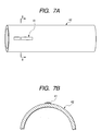
- FIGS. 7A and 7B are views showing a state in which a conventional radio frequency IC tag is affixed to a metal pipe.
- FIG. 7A is a perspective view and FIG. 7B is a fragmentary cross-sectional view taken along line E-E of FIG. 7A.
- a radio frequency IC tag 41 is affixed to a surface of a metal pipe 42 using an adhesive or the like.
- information stored on the IC chip that is, control information concerning attributes of the metallic material, such as material, dimensions, and the like
- an IC tag is affixed to a metallic object, such as an aluminum packaging material, a metal can, and the like.
- the IC tag contains information of various kinds that range from contents, manufacture, an expiry date, and the like.
- a measure is taken to prevent reading of the IC tag from becoming erratic as affected by a magnetic field produced by the metallic object.
- the measure taken may, for example, be a laminated structure of a resin plate, an insulation film, and an IC tag stacking one on top of another.
- the resin plate includes a ferrite powder with a predetermined magnetic permeability (see, for example, Japanese Patent Laid-open No. 2004-127057 (paragraph numbers 0014 through 0029, and FIG. 1), hereinafter referred to as "Patent Document 1").
- the radio frequency IC tag 41 is affixed to the surface of the metal pipe 42 as shown in FIGS. 7A and 7B.
- This arrangement makes the radio frequency IC tag 41 to protrude from the surface of the metal pipe 42.
- the radio frequency IC tag 41 tends to peel off the surface of the metal pipe 42.
- the radio frequency IC tag 41 is affixed to the metallic material by way of a relatively thick insulation film interposed therebetween. This is done to prevent radio frequency characteristics of the antenna from being affected by the metallic material. This results in the radio frequency IC tag 41 protruding so excessively from the surface of the metal pipe 42 that the IC tag 41 is easily peeled off.
- the resin plate, the insulation film, and the IC tag are stacked one on top of another and affixed to the metallic object to prevent radio waves transmitted from the IC tag from being affected by the metallic object.
- This arrangement results in the IC tag protruding substantially from the surface of the metallic object. The IC tag is therefore easy to come off.
- a radio frequency IC tag including an IC chip for storing information and an antenna for transmitting wirelessly the information stored on the IC chip.
- the radio frequency IC tag includes: an antenna substrate on one surface of which the IC chip is mounted at a substantial center of the surface, and which has a ground pattern formed at an area on which the IC chip is not mounted and electrically connected to the IC chip, the antenna substrate having a predetermined dielectric constant; an antenna radiation portion mounted on the other surface of the antenna substrate and electrically connected to an electrode terminal of the IC chip; and an outer casing accommodating therein the antenna substrate and the antenna radiation portion.
- the outer casing has, for example, a cylindrical outer surface or a threaded outer surface.
- a bolt with an IC tag includes a radio frequency IC tag mounted on a bolt.
- the radio frequency IC tag includes an IC chip for storing information and an antenna for transmitting wirelessly the information stored on the IC chip.
- a hole adapted to receive the radio frequency IC tag is formed in a head portion of the bolt. The radio frequency IC tag is stored in the hole so as not to protrude therefrom.
- the antenna includes, for example, a disk disposed at a position corresponding to a surface portion of the head portion of the bolt.
- a connection wire is extended from a center of the disk and connected to an electrode terminal of the IC chip.
- the distance from the disk to the electrode terminal of the IC chip is set to ⁇ /4 when the wavelength of a radio wave on the antenna substrate is ⁇ .
- the antenna forms a monopole antenna.
- FIGS. 1A to 1C are views showing a structure of a radio frequency IC tag according to a first preferred embodiment of the present invention, FIG. 1A being a perspective view showing the appearance, FIG. 1B being a top view, and FIG. 1C being a cross-sectional view taken along line A-A of FIG. 1B;
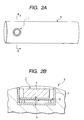
- FIGS. 2A and 2B are views showing a state in which the radio frequency IC tag shown in FIGS. 1A through 1C is mounted on a metal bar, FIG. 2A being a perspective view showing the appearance of the radio frequency IC tag mounted on the metal bar, and FIG. 2B being a fragmentary cross-sectional view taken along line B-B of FIG. 2A;
- FIGS. 3A and 3B are views showing a structure of a radio frequency IC tag according to a second preferred embodiment of the present invention, FIG. 3A being a top view, and FIG. 3B being a cross-sectional view taken along line C-C of FIG. 3A;
- FIGS. 4A and 4B are views showing a state in which the radio frequency IC tag shown in FIGS. 3A and 3B is mounted on a metal bar, FIG. 4A being a perspective view showing the appearance of the radio frequency IC tag mounted on the metal bar, and FIG. 4B being a fragmentary cross-sectional view taken along line D-D of FIG. 4A;
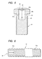
- FIG. 5 is a view showing a radio frequency IC tag mounted in a structure according to a third preferred embodiment of the present invention.
- FIG. 6 is a view showing a radio frequency IC tag mounted in a structure according to a fourth preferred embodiment of the present invention.
- FIGS. 7A and 7B are views showing a state in which the conventional radio frequency IC tag is mounted on a metal pipe, FIG. 7A being a perspective view showing the appearance thereof, and FIG. 7B being a fragmentary cross-sectional view taken along line E-E of FIG. 7A.
- the radio frequency IC tag according to the present invention uses an antenna of microstrip configuration.
- the microstrip configuration ensures that antenna characteristics are not degraded even if the IC tag is mounted on a metallic material.
- the antenna radiation portion is formed with a thick metal so as to provide a radiation surface for radio waves.
- the thick metal antenna radiation portion and the IC chip are filled with a resin or the like into interspace thereof.
- the radio frequency IC tag is thus offered as a sturdy, waterproof resin encapsulated structure.
- an entire body of the radio frequency IC tag is embedded and secured in the metallic material.
- the thick metal antenna portion serving as a radio wave radiation surface is exposed to the surface of the metallic material.
- FIGS. 1A to 1C are views showing a structure of a radio frequency IC tag according to a first preferred embodiment of the present invention.
- FIG. 1A is a perspective view showing the appearance of the radio frequency IC tag.
- FIG. 1B is a top view of the radio frequency IC tag.
- FIG. 1C is a cross-sectional view taken along line A-A of FIG. 1B.
- a radio frequency IC tag 1 includes an antenna substrate 3 and an antenna radiation portion 4 which are accommodated in an outer casing 2.
- the outer casing 2 is formed of metal, such as iron, stainless steel, aluminum, or the like, or resin, such as Polyvinyl Chloride (PVC), Acrylonitrile Butadiene Styrene polymer (ABS), or the like.
- the antenna substrate 3 is formed of glass epoxy board or the like.
- the antenna radiation portion 4 is formed of metal. To explain in greater detail, referring to FIGS. 1B and 1C, the antenna substrate 3 is placed on top of support members 8 made of resin and formed on a bottom portion of the outer casing 2. The antenna radiation portion 4 made of metal and formed into a thick cylindrical column is then mounted on the antenna substrate 3.
- the support members 8 are protrusions for controlling a height of the antenna substrate 3 relative to the bottom portion of the outer casing 2.
- a through electrode 6 penetrates through a through hole provided at a position slightly offset from the center of the antenna substrate 3.
- the through electrode 6 extends from the rear surface to above the front surface (i.e. upper surface in Fig. 1C) of the antenna substrate 3.
- An IC chip 5 is disposed on a backside of the antenna substrate 3 to cover an area that extends from a position corresponding to the through electrode 6 to the center part of the antenna substrate 3.
- One of electrode terminals (not shown) of the IC chip 5 is connected to the through electrode 6.
- a ground pattern (not shown) is formed to cover substantially the entire surface of the backside of the antenna substrate 3, except the area on which the IC chip 5 is disposed.
- the other electrode terminal of the IC chip 5 is connected to the ground pattern.
- the antenna radiation portion 4 made of metal and formed into the thick cylindrical column is mounted on the front side of the antenna substrate 3 at the center thereof.
- the antenna radiation portion 4 is connected to the through electrode 6.
- a head of the cylindrical column of the antenna radiation portion 4 is substantially as high as, or slightly lower than, the outer casing 2.
- a sealing agent 7, such as an epoxy resin or the like used as a semiconductor packaging material, is injected into the inside of the outer casing 2 and then cured.
- the radio frequency 1C tag 1 as configured as shown in FIGS. 1A to 1C is achieved.
- An antenna of a microstrip structure is herein achieved through the arrangement, in which the ground pattern (not shown) is formed on the backside of the antenna substrate 3 and the antenna radiation portion 4 is formed on the front side thereof. Radio waves from the antenna radiation portion 4 can therefore be prevented from being affected by the metallic portions located therearound through a shield function of the ground pattern.
- the radio frequency IC tag is attached to a metal bar as a controlled material, therefore, there is no likelihood that the antenna radio waves are absorbed by a metallic material existing at any location below the bottom portion of the outer casing 2.
- the antenna radiation portion 4 can therefore secure effectively directivity of radio waves at the head of the cylindrical column.
- an ordinary strip antenna an antenna having no ground patterns on the backside of the substrate
- radio waves of the antenna are absorbed by the metal, causing the radio waves to lose directivity.
- the microstrip antenna as described above allows directivity of the radio waves to be properly maintained even if the antenna is disposed on the surface of a metal or the like.
- the through electrode 6 is disposed slightly offset from the center of the antenna radiation portion 4 in the antenna substrate 3. This is done to achieve impedance matching of the antenna. Specifically, since there is zero potential at the center of the antenna radiation portion 4, the electrode terminal of the IC chip is connected at a position slightly deviated from the center of the antenna radiation portion 4, thereby achieving impedance matching between the IC chip and the antenna.
- the diameter of the cylindrical column of the antenna radiation portion 4 is set to ⁇ /2 when the wavelength of the radio wave on the antenna substrate is ⁇ .
- varying the dielectric constant of the antenna substrate 3 changes a resonance frequency of the antenna substrate 3. This, in turn, means that, by varying the dielectric constant of the antenna substrate 3, the diameter of the antenna radiation portion 4 can be selectively varied.
- selecting the dielectric constant of the antenna substrate 3 that is, selecting the material of the antenna substrate 3) allows the diameter of the antenna radiation portion 4 to be determined.
- the diameter of the antenna radiation portion 4 can be made small to build a small radio frequency IC tag by making the dielectric constant of the antenna substrate 3 large.
- the diameter of the antenna radiation portion 4 made small, however, results in radiation characteristics of the radio waves being aggravated. It is therefore desirable that the material of the antenna substrate 3 be selected such that trade-off between a smaller antenna substrate 3 and degraded radio wave radiation characteristics is optimized. The diameter of the antenna radiation portion 4 is thereby optimally established.
- the radio frequency IC tag Use of the radio frequency IC tag on a relatively large-sized metal bar or metal pipe is herein assumed. If, for example, the antenna substrate 3 having a dielectric constant of 10 is selected with a special emphasis placed on wave radiation characteristics rather than compactness, the diameter of the cylindrical column of the antenna radiation portion 4 is 24 mm. At this time, a radio frequency IC tag can be realized of a cylindrical column that measures 36 mm in diameter and about 16.6 mm in height. The height of the antenna radiation portion 4 is set to a value more than a machining margin of a controlled material (e.g., a metal bar or the like), on which the radio frequency IC tag 1 is mounted.
- a controlled material e.g., a metal bar or the like
- FIGS. 2A and 2B are views showing a state in which the radio frequency IC tag shown in FIGS. 1A through 1C is mounted on a metal bar.
- FIG. 2A is a perspective view showing the appearance of the radio frequency IC tag mounted on the metal bar.
- FIG. 2B is a partial cross-sectional view taken along line B-B of FIG. 2A. Specifically, a hole with a desired diameter and a desired depth is made in a metal bar 9. The radio frequency IC tag 1 as configured as shown in FIGS. 1A through 1C is then press-fitted into the hole. This allows the radio frequency IC tag 1 to be stably secured in the metal bar 9.
- the radio frequency IC tag 1 is press-fitted into the hole until the head of the antenna radiation portion 4 is substantially flush with a surface of the metal bar 9. This eliminates the possibility that the radio frequency IC tag 1 protrudes from the surface of the metal bar 9.
- the radio frequency IC tag 1 can therefore be secured in the metal bar 9 even more stably.
- a reader (not shown) is then brought near to the antenna radiation portion 4 of the radio frequency IC tag 1 secured in the metal bar 9, the reader can easily read information stored on the IC chip 5 through transmission and reception of radio waves between the reader and the antenna radiation portion 4.
- the diameter of the antenna radiation portion 4 is relatively large to ensure directivity covering radio waves going in wider directions. The reader can therefore read data of the radio frequency IC tag 1 easily over a relatively wide range.
- the metal bar 9 may be ground or otherwise machined after the radio frequency IC tag 1 has been press-fitted into the metal bar 9. Meantime, the height of the cylindrical column of the antenna radiation portion 4 in the radio frequency IC tag 1 is set to a level greater than, and according to, the machining margin. Even if the metal bar 9 is machined, therefore, the cylindrical column of the antenna radiation portion 4 is left unmachined. As a result, the antenna characteristics are maintained. Even if the metal bar 9 is machined as necessary at an assembly stage of a structure, therefore, there is no likelihood that the radio frequency IC tag 1 will become disabled, enhancing usability.
- the arrangements made for the radio frequency IC tag as described in the foregoing allows the IC tag to be embedded in the metallic material as the controlled material. This eliminates the possibility of the radio frequency IC tag being peeled off the metallic material. There is also relatively less chance of the radio frequency IC tag being damaged through contact with other objects. It is therefore possible to carry out communications stably between the radio frequency IC tag and the reader at all times. The information stored on the IC chip can therefore be read accurately and positively.
- FIGS. 3A and 3B are views showing a structure of a radio frequency IC tag according to a second preferred embodiment of the present invention.
- FIG. 3A is a top view.
- FIG. 3B is a cross-sectional view taken along line C-C of FIG. 3A.
- the structure of a radio frequency IC tag 11 according to the second embodiment differs from that of the radio frequency IC tag 1 according to the first embodiment in the following points only. Specifically, a thread 12a is machined on the outer peripheral surface of an outer casing 12' and a plurality of mounting jig holes 13 are provided in the upper end surface of the outer casing.
- the same material as in the first embodiment is used for the outer casing 12'. Possible types of materials include metal, such as iron, stainless steel, aluminum, or the like, and resin, such as PVC, ABS, or the like.
- the construction of the radio frequency IC tag is exactly the same as that shown in FIGS. 1A to 1C. The description of the radio frequency IC tag will therefore be omitted.
- FIGS. 4A and 4B are views showing a state in which the radio frequency IC tag shown in FIGS. 3A and 3B is mounted on a metal bar.
- FIG. 4A is a perspective view showing the appearance of the radio frequency IC tag mounted on the metal bar.
- FIG. 4B is a fragmentary cross-sectional view taken along line D-D of FIG. 4A. Specifically, a thread groove having a desired diameter and a desired depth is formed in a metal bar 9 in advance.
- a mounting jig (not shown) is inserted in the mounting jig holes 13 provided in the upper end surface of the outer casing 12' and the radio frequency IC tag 11 is then screwed into the metal bar 9.
- the radio frequency IC tag 11 is secured in the metal bar 9 with a head of an antenna radiation portion 4 being substantially flush with a surface of the metal bar 9. This allows the radio frequency IC tag 11 to be stably secured in the metal bar 9 without allowing the radio frequency IC tag 11 to protrude from the surface of the metal bar 9.
- the metal bar 9 can be machined in the same manner as in the first embodiment after the radio frequency IC tag 11 has been screwed in the metal bar 9.
- FIG. 5 is a view showing a radio frequency IC tag mounted in a structure according to a third preferred embodiment of the present invention. Specifically, a hole 21a having a desired diameter and a desired depth is made in a head of a bolt 21 as a controlled material and a radio frequency IC tag 22 is embedded in the hole 21a for use with the bolt.
- An antenna 24 of the radio frequency IC tag 22 includes a disk 24a having a diameter smaller than that of the hole 21a.
- a connection wire 24b is extended from a center of the disk 24a and connected to an electrode terminal of an IC chip 23. Another electrode terminal of the IC chip 23 is connected to the bolt 21.
- the distance between the disk 24a and the electrode of the IC chip 23 is set to ⁇ /4 when a wavelength of the radio wave to be used on a sealing agent 25 (antenna substrate) is ⁇ .
- An antenna 24 as a monopole antenna is configured as described in the foregoing. Radio waves can then be radiated from the disk 24a located on a surface portion of the head of the bolt 21.
- the radio frequency IC tag 22 is secured in the bolt 21 as below. Specifically, with the IC chip 23 and the like housed in the hole 21a in the bolt 21, the disk 24a is fixed at a position substantially flush with the surface of the head of the bolt 21. Then, the sealing agent 25, such as an epoxy resin or the like used as a semiconductor packaging material, is injected into the hole 21a and then cured.
- the sealing agent 25 such as an epoxy resin or the like used as a semiconductor packaging material
- the reader When a reader (not shown) is brought near to the bolt 21, the reader can relatively easily receive radio waves from the antenna 24, thereby reading information stored on the IC chip 23 without being affected by the bolt 21 that may be made of metal.
- FIG. 6 is a view of a radio frequency IC tag mounted in a structure according to a fourth preferred embodiment of the present invention.
- a stud bolt 31 is herein used as a controlled material.
- a radio frequency IC tag 32 can be embedded in a head of a part-fixing portion 31b of the stud bolt 31 by following the procedure as described with reference to FIG. 5.
- an assembly member can be screwed and mounted to the part fixing portion 31b. The specific assembly member screwed together to the stud bolt 31 can then be identified and managed by reading information stored in the radio frequency IC tag 32 fixed to the head of the stud bolt 31.
- the function offered by the IC tag may be protected intact even if a surface of a metal pipe or a metal bar is reground or otherwise machined after the radio frequency IC tag has been mounted in the metal.
- the radio frequency IC tag according to the present invention can be mounted in a metal material and effectively utilized in, for example, a building structure or the like.
- the radio frequency IC tag can be embedded in a bolt. It is therefore possible to control a mounting position and details of a part in an engine, a machine tool, or other metallic equipment. The radio frequency IC tag can therefore effectively support assembly work of complicated structures.
- the radio frequency IC tags according to the embodiments as described in the foregoing can be embedded in a metal bar or a metal pipe through press-fitting or screwing the tag until the tag is flush with a surface of the metal bar or the metal pipe.
- the radio frequency IC tag can therefore be secured to the metal bar or the metal pipe without allowing the tag to protrude from the surface of the metal bar or pipe.
- the radio frequency IC tag can be effectively prevented from coming off or being damaged during handling of the metal bar or the like. Reliability in use of the radio frequency IC tag can therefore be even more enhanced.
- the antenna radiation portion is exposed on the surface of the metal bar or the metal pipe. A high antenna directivity can therefore be maintained to allow the antenna radiation portion to receive radio waves accurately.
- the reader can therefore read information stored on the radio frequency IC tag even more accurately and positively.
- the radio frequency IC tag is housed in the hole in the head of the bolt.
- the radio frequency IC tag can therefore be prevented from coming off from the bolt or being damaged effectively.
- the antenna of the radio frequency IC tag includes the disk disposed on the surface of the bolt head.
- the distance between the electrode terminals of the IC chip electrically connected to the disk through the connection wire is set according to the wavelength ⁇ of the radio wave on the antenna substrate.
Landscapes
- Engineering & Computer Science (AREA)
- Physics & Mathematics (AREA)
- General Physics & Mathematics (AREA)
- Theoretical Computer Science (AREA)
- Computer Hardware Design (AREA)
- Microelectronics & Electronic Packaging (AREA)
- Electromagnetism (AREA)
- Details Of Aerials (AREA)
- Credit Cards Or The Like (AREA)
- Support Of Aerials (AREA)
- Aerials With Secondary Devices (AREA)
Applications Claiming Priority (1)
| Application Number | Priority Date | Filing Date | Title |
|---|---|---|---|
| JP2004219678A JP4477961B2 (ja) | 2004-07-28 | 2004-07-28 | Icタグ付きボルト |
Publications (2)
| Publication Number | Publication Date |
|---|---|
| EP1622069A1 true EP1622069A1 (fr) | 2006-02-01 |
| EP1622069B1 EP1622069B1 (fr) | 2011-03-23 |
Family
ID=35004196
Family Applications (1)
| Application Number | Title | Priority Date | Filing Date |
|---|---|---|---|
| EP04257816A Expired - Lifetime EP1622069B1 (fr) | 2004-07-28 | 2004-12-15 | Tanspondeur RF et boulon avec transpondeur RF |
Country Status (7)
| Country | Link |
|---|---|
| US (1) | US7256697B2 (fr) |
| EP (1) | EP1622069B1 (fr) |
| JP (1) | JP4477961B2 (fr) |
| KR (1) | KR100690464B1 (fr) |
| CN (1) | CN100369060C (fr) |
| DE (1) | DE602004031937D1 (fr) |
| TW (1) | TWI292558B (fr) |
Cited By (2)
| Publication number | Priority date | Publication date | Assignee | Title |
|---|---|---|---|---|
| WO2009100729A1 (fr) * | 2008-02-12 | 2009-08-20 | Siemens Aktiengesellschaft | Marque d'identification pour identifier des objets à surface métallique |
| WO2021094107A1 (fr) * | 2019-11-15 | 2021-05-20 | Bayerische Motoren Werke Aktiengesellschaft | Antenne de véhicule vissable |
Families Citing this family (73)
| Publication number | Priority date | Publication date | Assignee | Title |
|---|---|---|---|---|
| US7256699B2 (en) * | 2005-03-24 | 2007-08-14 | Sdgi Holdings, Inc. | Button-type RFID tag |
| FR2884681B1 (fr) * | 2005-04-15 | 2007-06-22 | St Microelectronics Sa | Antenne pour etiquette electronique |
| AR050177A1 (es) * | 2005-07-21 | 2006-10-04 | Siderca Sa Ind & Com | "un conjunto de tubo metalico y de etiquetas de identificacion por radiofrecuencia (rfid)" |
| NO326442B1 (no) * | 2005-08-22 | 2008-12-08 | Nat Oilwell Norway As | Fremgangsmate for innfesting av en hurtig avlesbar databrikke i metalliske overflater for elektronisk identifikasjon. |
| EP1783668A3 (fr) * | 2005-09-29 | 2007-05-16 | Harting Mitronics AG | Unité de transpondeur |
| US20070145129A1 (en) * | 2005-12-27 | 2007-06-28 | Perkin Gregg S | System and method for identifying equipment |
| JP4915110B2 (ja) * | 2006-03-10 | 2012-04-11 | 大日本印刷株式会社 | Icタグの着脱可能取付構造 |
| JP2007256994A (ja) * | 2006-03-20 | 2007-10-04 | Disco Abrasive Syst Ltd | Icタグの装着方法及び雄ねじ |
| JP4648972B2 (ja) * | 2006-07-24 | 2011-03-09 | 株式会社ハネックス | 平ワッシャ型タグ |
| US7412898B1 (en) | 2006-07-28 | 2008-08-19 | Disney Enterprises, Inc. | Load sensing system including RFID tagged fasteners |
| JP4956152B2 (ja) | 2006-11-21 | 2012-06-20 | 株式会社スマート | センサ・タグの多面影像方式 |
| KR100832162B1 (ko) * | 2007-01-24 | 2008-05-23 | 주식회사 사라콤 | Rfid 태그 볼트 및 차량용 번호판 장치 |
| KR100886890B1 (ko) | 2007-03-20 | 2009-03-06 | (주)케이피씨 | 전자봉인장치 및 그를 이용한 개방감지방법 |
| JP4814842B2 (ja) * | 2007-06-04 | 2011-11-16 | 株式会社神戸製鋼所 | Icタグユニット |
| JP2009037416A (ja) * | 2007-08-01 | 2009-02-19 | Kajima Corp | アンテナの取付構造、ジョイント部材、及び送受信システム |
| EP2201502A4 (fr) * | 2007-10-16 | 2010-11-10 | Confidex Oy | Procédé pour un étiquetage rfid |
| TW200924640A (en) * | 2007-12-06 | 2009-06-16 | jian-xun He | Ecological shell capable of providing house for hermit crab |
| TWI334464B (en) * | 2007-12-13 | 2010-12-11 | Ind Tech Res Inst | Fixing element and inspection system thereof |
| KR101020668B1 (ko) * | 2007-12-27 | 2011-03-09 | 순천대학교 산학협력단 | Rfid 태그 패키지 및 rfid 태그 패키징 방법 |
| EP2278661A4 (fr) * | 2008-04-25 | 2017-08-30 | Toda Kogyo Corporation | Antenne magnétique, substrat présentant l'antenne magnétique montée sur celui-ci, et étiquette radiofréquence |
| JP4896922B2 (ja) * | 2008-05-01 | 2012-03-14 | 富士通株式会社 | 無線タグ及び無線タグを有する導電性パイプ |
| JP5239499B2 (ja) * | 2008-05-13 | 2013-07-17 | 戸田工業株式会社 | 複合磁性体アンテナ及びrfタグ、該複合磁性体アンテナ又はrfタグを設置した金属部品、金属工具 |
| US8514060B2 (en) * | 2008-05-21 | 2013-08-20 | Mitomo Corporation | Wireless identification tag |
| US20100096455A1 (en) * | 2008-10-16 | 2010-04-22 | Merrick Systems Inc. | Edge mounted rfid tag |
| JP2010128937A (ja) | 2008-11-28 | 2010-06-10 | Fujitsu Ltd | Rfidユニット |
| JP5284858B2 (ja) | 2009-04-22 | 2013-09-11 | 富士通株式会社 | Rfidタグ |
| CN102971485B (zh) | 2010-04-30 | 2016-01-13 | S.P.M.流量控制股份有限公司 | 测试和认证石油和天然气设备的机器、系统、计算机实施的方法 |
| DE102011016132A1 (de) * | 2011-03-29 | 2012-10-04 | Newfrey Llc | Bolzenfügeverfahren und Werkzeuge hierfür |
| CN103765444B (zh) * | 2011-07-01 | 2017-08-25 | Ntn株式会社 | 附带ic标签的轴承装置 |
| US9898698B2 (en) | 2011-07-01 | 2018-02-20 | The Boeing Company | Production tool having RFID device mounted within a dielectric inclusion |
| US8448520B1 (en) | 2011-12-06 | 2013-05-28 | King Fahd University Of Petroleum And Minerals | Bolt tension monitoring system |
| JP2013152600A (ja) * | 2012-01-25 | 2013-08-08 | Hitachi Chemical Co Ltd | Rfidタグシステム及びrfidパッケージ |
| JP5639606B2 (ja) * | 2012-02-27 | 2014-12-10 | 三智商事株式会社 | 無線icタグ |
| USD713825S1 (en) | 2012-05-09 | 2014-09-23 | S.P.M. Flow Control, Inc. | Electronic device holder |
| AU2013266252B2 (en) | 2012-05-25 | 2017-07-06 | Spm Oil & Gas Inc. | Evaluating systems associated with wellheads |
| CA2815864C (fr) * | 2012-06-30 | 2018-04-17 | The Boeing Company | Outil de production pourvu d'un dispositif rfid monte dans une inclusion dielectrique |
| US20150041162A1 (en) * | 2013-08-06 | 2015-02-12 | China Pneumatic Corporation | Programmable torque control method for sensing locking element |
| CN105706116B (zh) * | 2013-09-12 | 2019-02-15 | 雷肖尔股份公司 | 用于机床的金属更换部件的射频识别标记 |
| US9067766B1 (en) | 2013-09-16 | 2015-06-30 | Jergens, Inc. | Hoisting device and system and method for using the same |
| JP6244890B2 (ja) * | 2013-12-24 | 2017-12-13 | 株式会社デンソーウェーブ | 情報読取装置 |
| US9649640B2 (en) * | 2014-04-16 | 2017-05-16 | Flsmidth A/S | Methods and apparatus for the continuous monitoring of wear in flotation circuits |
| EP2942739A1 (fr) * | 2014-05-07 | 2015-11-11 | Siemens Aktiengesellschaft | Fixation pour transpondeur RFID, transpondeur RFID et outil d'actionnement |
| GB2544671A (en) | 2014-07-30 | 2017-05-24 | Spm Flow Control Inc | Band with RFID chip holder and identifying component |
| CN104239913A (zh) * | 2014-08-15 | 2014-12-24 | 深圳麦格米特电气股份有限公司 | 列车车轮上电子标签的安装方法和列车车轮的注油孔螺塞 |
| USD750516S1 (en) | 2014-09-26 | 2016-03-01 | S.P.M. Flow Control, Inc. | Electronic device holder |
| US10450174B1 (en) | 2014-10-07 | 2019-10-22 | Jergens, Inc. | Hoisting device and bolt for use therewith, method of making and using the same |
| US10007874B1 (en) * | 2015-01-19 | 2018-06-26 | Balluff Gmbh | Clamping bolt with integrated RFID transponder |
| CN104647260A (zh) * | 2015-03-08 | 2015-05-27 | 杜婉璐 | 一种具有智能识别系统的螺丝刀 |
| WO2016187503A1 (fr) | 2015-05-21 | 2016-11-24 | Texas Nameplate Company, Inc. | Procédé et système pour fixer un dispositif de suivi à un composant |
| JP6095733B2 (ja) * | 2015-06-30 | 2017-03-15 | 株式会社Iro | 杵部材、臼部材およびロータリプレス装置 |
| US10941802B2 (en) * | 2015-07-13 | 2021-03-09 | Silicon Valley Micro E Corp. | Intelligent washer |
| WO2017030870A1 (fr) | 2015-08-14 | 2017-02-23 | S.P.M. Flow Control, Inc. | Ensemble support et bande pour identifier et gérer un élément d'un système associé à une tête de puits |
| US9964135B2 (en) | 2015-12-16 | 2018-05-08 | Cameron International Corporation | Smart washer for pre-load monitoring |
| JP6548123B2 (ja) * | 2016-03-03 | 2019-07-24 | 株式会社フェニックスソリューション | Rfタグ |
| JP6575541B2 (ja) * | 2017-02-06 | 2019-09-18 | カシオ計算機株式会社 | 無線機器 |
| DE102017112667A1 (de) * | 2017-06-08 | 2018-12-13 | Gemü Gebr. Müller Apparatebau Gmbh & Co. Kommanditgesellschaft | Mehrwege-Ventilkörper und Verfahren zum Herstellen des Mehrwege-Ventilkörpers |
| CN111868748A (zh) * | 2018-01-11 | 2020-10-30 | G·格罗夫 | 带有嵌入式rfid标签的金属紧固件及其生产方法 |
| US10719748B2 (en) * | 2018-02-28 | 2020-07-21 | Paul Salsberg | RFID screw specifically for use on eyeglass frames |
| DE102018109599B3 (de) | 2018-04-20 | 2019-07-18 | Rittal Gmbh & Co. Kg | Schaltschrankgehäuse mit Bauteilkennzeichnung sowie ein entsprechendes Herstellungsverfahren |
| SE542229C2 (en) * | 2018-07-02 | 2020-03-17 | Stora Enso Oyj | A metal container comprising a uhf rfid tag |
| CN109034340A (zh) * | 2018-08-06 | 2018-12-18 | 天津云拓网络科技有限公司 | 一种监测螺栓松动的电子标签 |
| US10938447B1 (en) * | 2019-08-08 | 2021-03-02 | The Boeing Company | Radio-frequency-identification-based smart fastener |
| US11074490B2 (en) * | 2019-10-24 | 2021-07-27 | The Boeing Company | Intelligent fasteners |
| CN111860737B (zh) * | 2020-05-25 | 2025-04-18 | 上海联贤智能科技有限公司 | 一种小型化超高频rfid标签 |
| DE102020122072A1 (de) * | 2020-08-24 | 2022-02-24 | Neosid Pemetzrieder Gmbh & Co. Kg | Transponderkappe |
| EP4213069A4 (fr) * | 2020-09-08 | 2024-09-11 | General Co., Ltd. | Élément de montage avec étiquette rfid, procédé de fabrication d'élément de montage avec étiquette rfid, unité tête d'élément de montage avec étiquette rfid, et unité de montage d'étiquette rfid |
| CN112288070A (zh) * | 2020-11-04 | 2021-01-29 | 宁波亦芯电子科技有限公司 | 一种钻杆标签和钻杆及其应用 |
| JP7264861B2 (ja) * | 2020-11-11 | 2023-04-25 | 矢崎総業株式会社 | 薄型アンテナ |
| CN112508157A (zh) * | 2020-12-18 | 2021-03-16 | 青岛海威物联科技有限公司 | Rfid标签固定结构、rfid标签及rfid标签安装方法 |
| TWI878713B (zh) * | 2021-08-25 | 2025-04-01 | 新加坡商艾波路普科技私人有限公司 | 首飾以及製造rfid裝置的方法 |
| US12423553B2 (en) * | 2021-08-25 | 2025-09-23 | Experloop Technology Pte. Ltd. | RFID arrangement, piece of jewelry, local sending arrangement, and methods |
| CN114118335B (zh) * | 2021-12-28 | 2024-12-03 | 苏州微明医疗科技有限公司 | 一种全向抗金属超高频rfid标签及医疗器械 |
| CN118871685B (zh) * | 2022-03-30 | 2025-07-08 | 尾高橡胶工业株式会社 | 辊 |
Citations (7)
| Publication number | Priority date | Publication date | Assignee | Title |
|---|---|---|---|---|
| US5394159A (en) * | 1993-11-02 | 1995-02-28 | At&T Corp. | Microstrip patch antenna with embedded detector |
| US5995048A (en) * | 1996-05-31 | 1999-11-30 | Lucent Technologies Inc. | Quarter wave patch antenna |
| JP2000304870A (ja) * | 1999-04-23 | 2000-11-02 | Matsushita Electric Works Ltd | Idタグ |
| US6239737B1 (en) * | 1994-07-15 | 2001-05-29 | Micron Technology, Inc. | Method and apparatus for attaching a radio frequency transponder to an object |
| DE10056473C1 (de) * | 2000-11-15 | 2002-01-17 | Infineon Technologies Ag | Transponder |
| US20030156033A1 (en) * | 2001-01-12 | 2003-08-21 | Paul C. Koomey | Apparatus and method for assembly, retention and physical protection of radio frequency identification tags for oil drill strings |
| US20030169207A1 (en) * | 2002-03-05 | 2003-09-11 | Precision Dynamics Corporation | Microstrip antenna for an identification appliance |
Family Cites Families (16)
| Publication number | Priority date | Publication date | Assignee | Title |
|---|---|---|---|---|
| US6045652A (en) * | 1992-06-17 | 2000-04-04 | Micron Communications, Inc. | Method of manufacturing an enclosed transceiver |
| EP0704928A3 (fr) * | 1994-09-30 | 1998-08-05 | HID Corporation | Système transpondeur radiofréquence avec interrogation à résonance parallèle et réponse à résonance en série |
| US5880675A (en) * | 1995-05-19 | 1999-03-09 | Texas Instruments Incorporated | Reusable package for identification devices |
| TW350054B (en) * | 1996-11-29 | 1999-01-11 | Mitsubishi Materials Corp | Burglarproof label |
| US6049278A (en) * | 1997-03-24 | 2000-04-11 | Northrop Grumman Corporation | Monitor tag with patch antenna |
| US6204771B1 (en) * | 1997-08-19 | 2001-03-20 | Ronald C. Clarke | Load indicating fastener systems method and apparatus |
| US7009506B2 (en) * | 1998-02-10 | 2006-03-07 | Bridgestone Firestone North American Tire, Llc | Electronic monitoring device and patch assembly |
| EP0963004B1 (fr) * | 1998-06-04 | 2004-02-04 | Matsushita Electric Industrial Co., Ltd. | Antenne monopole |
| US6452497B1 (en) * | 1998-09-02 | 2002-09-17 | Frank John Finlayson | Carrier identification device |
| US6494305B1 (en) * | 1998-12-14 | 2002-12-17 | Micron Technology, Inc. | Carcass-tracking apparatus housing carcass-tracking apparatus and carcass-tracking methods |
| JP3711026B2 (ja) * | 2000-07-17 | 2005-10-26 | 株式会社ハネックス | Rfidタグの設置構造及びrfidタグの設置方法及びrfidタグの通信方法 |
| JP3960523B2 (ja) | 2002-02-13 | 2007-08-15 | 株式会社日立製作所 | 無線タグ、無線タグ束、及び無線タグ装着装置 |
| JP4082162B2 (ja) | 2002-10-04 | 2008-04-30 | 凸版印刷株式会社 | Icタグ付き包装材料 |
| US7079078B2 (en) * | 2003-04-09 | 2006-07-18 | Alps Electric Co., Ltd. | Patch antenna apparatus preferable for receiving ground wave and signal wave from low elevation angle satellite |
| US6814287B1 (en) * | 2003-06-02 | 2004-11-09 | Industrial Technology Research Institute | Pallet apparatus equipped with a radio frequency recognition module |
| US7755484B2 (en) * | 2004-02-12 | 2010-07-13 | Avery Dennison Corporation | RFID tag and method of manufacturing the same |
-
2004
- 2004-07-28 JP JP2004219678A patent/JP4477961B2/ja not_active Expired - Lifetime
- 2004-11-23 TW TW093135963A patent/TWI292558B/zh not_active IP Right Cessation
- 2004-12-14 US US11/010,300 patent/US7256697B2/en not_active Expired - Fee Related
- 2004-12-15 DE DE602004031937T patent/DE602004031937D1/de not_active Expired - Lifetime
- 2004-12-15 EP EP04257816A patent/EP1622069B1/fr not_active Expired - Lifetime
- 2004-12-17 KR KR1020040107480A patent/KR100690464B1/ko not_active Expired - Fee Related
- 2004-12-28 CN CNB2004100817470A patent/CN100369060C/zh not_active Expired - Fee Related
Patent Citations (7)
| Publication number | Priority date | Publication date | Assignee | Title |
|---|---|---|---|---|
| US5394159A (en) * | 1993-11-02 | 1995-02-28 | At&T Corp. | Microstrip patch antenna with embedded detector |
| US6239737B1 (en) * | 1994-07-15 | 2001-05-29 | Micron Technology, Inc. | Method and apparatus for attaching a radio frequency transponder to an object |
| US5995048A (en) * | 1996-05-31 | 1999-11-30 | Lucent Technologies Inc. | Quarter wave patch antenna |
| JP2000304870A (ja) * | 1999-04-23 | 2000-11-02 | Matsushita Electric Works Ltd | Idタグ |
| DE10056473C1 (de) * | 2000-11-15 | 2002-01-17 | Infineon Technologies Ag | Transponder |
| US20030156033A1 (en) * | 2001-01-12 | 2003-08-21 | Paul C. Koomey | Apparatus and method for assembly, retention and physical protection of radio frequency identification tags for oil drill strings |
| US20030169207A1 (en) * | 2002-03-05 | 2003-09-11 | Precision Dynamics Corporation | Microstrip antenna for an identification appliance |
Non-Patent Citations (1)
| Title |
|---|
| PATENT ABSTRACTS OF JAPAN vol. 2000, no. 14 5 March 2001 (2001-03-05) * |
Cited By (4)
| Publication number | Priority date | Publication date | Assignee | Title |
|---|---|---|---|---|
| WO2009100729A1 (fr) * | 2008-02-12 | 2009-08-20 | Siemens Aktiengesellschaft | Marque d'identification pour identifier des objets à surface métallique |
| WO2021094107A1 (fr) * | 2019-11-15 | 2021-05-20 | Bayerische Motoren Werke Aktiengesellschaft | Antenne de véhicule vissable |
| CN114424403A (zh) * | 2019-11-15 | 2022-04-29 | 宝马股份公司 | 可拧入式车辆天线 |
| US12003022B2 (en) | 2019-11-15 | 2024-06-04 | Bayerische Motoren Werke Aktiengesellschaft | Screwable vehicle antenna |
Also Published As
| Publication number | Publication date |
|---|---|
| JP4477961B2 (ja) | 2010-06-09 |
| EP1622069B1 (fr) | 2011-03-23 |
| US7256697B2 (en) | 2007-08-14 |
| KR20060010688A (ko) | 2006-02-02 |
| JP2006039991A (ja) | 2006-02-09 |
| TW200604956A (en) | 2006-02-01 |
| TWI292558B (en) | 2008-01-11 |
| CN100369060C (zh) | 2008-02-13 |
| KR100690464B1 (ko) | 2007-03-09 |
| US20060022056A1 (en) | 2006-02-02 |
| DE602004031937D1 (de) | 2011-05-05 |
| CN1728164A (zh) | 2006-02-01 |
Similar Documents
| Publication | Publication Date | Title |
|---|---|---|
| US7256697B2 (en) | Radio frequency IC tag and bolt with an IC tag | |
| US11301744B2 (en) | Metal smart card with dual interface capability | |
| CA3099670C (fr) | Carte a puce metallique a double interface munie d'une antenne amplificatrice | |
| US9390366B1 (en) | Metal smart card with dual interface capability | |
| KR100848748B1 (ko) | Rfic 태그와 그 사용 방법 | |
| US10289944B2 (en) | Metal smart card with dual interface capability | |
| US20160180212A1 (en) | Smart metal card with radio frequency (rf) transmission capability | |
| KR102018904B1 (ko) | Rf 태그 | |
| US7012530B2 (en) | Electronic label | |
| JPH11509024A (ja) | カードまたはラベル用の非接触電子モジュール | |
| US11809939B2 (en) | RFID tag with boost antenna, conductor provided with RFID tag with boost antenna, and RFID system including RFID tag with boost antenna | |
| US7227721B1 (en) | Multi-directional cartridge memory antenna designs | |
| JP4878266B2 (ja) | Rfidタグ | |
| HK1085295A (en) | Radio frequency ic tag and bolt with an ic tag | |
| JP2005130211A (ja) | 携帯無線機および電池 | |
| TWI298139B (en) | Antenna and tag for rfid using the antenna | |
| JP4475258B2 (ja) | 無線タグ | |
| HK40085310B (en) | Dual interface metal smart card with booster antenna | |
| CN118661176A (zh) | Rfid标签组件和具有rfid标签组件的待识别物体 | |
| HK40085310A (en) | Dual interface metal smart card with booster antenna | |
| JP2000099674A (ja) | 非接触伝達機構付icカード |
Legal Events
| Date | Code | Title | Description |
|---|---|---|---|
| PUAI | Public reference made under article 153(3) epc to a published international application that has entered the european phase |
Free format text: ORIGINAL CODE: 0009012 |
|
| 17P | Request for examination filed |
Effective date: 20050113 |
|
| AK | Designated contracting states |
Kind code of ref document: A1 Designated state(s): AT BE BG CH CY CZ DE DK EE ES FI FR GB GR HU IE IS IT LI LT LU MC NL PL PT RO SE SI SK TR |
|
| AX | Request for extension of the european patent |
Extension state: AL BA HR LV MK YU |
|
| REG | Reference to a national code |
Ref country code: HK Ref legal event code: DE Ref document number: 1085295 Country of ref document: HK |
|
| AKX | Designation fees paid |
Designated state(s): DE FR GB |
|
| 17Q | First examination report despatched |
Effective date: 20070717 |
|
| GRAP | Despatch of communication of intention to grant a patent |
Free format text: ORIGINAL CODE: EPIDOSNIGR1 |
|
| GRAS | Grant fee paid |
Free format text: ORIGINAL CODE: EPIDOSNIGR3 |
|
| GRAA | (expected) grant |
Free format text: ORIGINAL CODE: 0009210 |
|
| AK | Designated contracting states |
Kind code of ref document: B1 Designated state(s): DE FR GB |
|
| REG | Reference to a national code |
Ref country code: GB Ref legal event code: FG4D |
|
| REF | Corresponds to: |
Ref document number: 602004031937 Country of ref document: DE Date of ref document: 20110505 Kind code of ref document: P |
|
| REG | Reference to a national code |
Ref country code: DE Ref legal event code: R096 Ref document number: 602004031937 Country of ref document: DE Effective date: 20110505 |
|
| PLBE | No opposition filed within time limit |
Free format text: ORIGINAL CODE: 0009261 |
|
| STAA | Information on the status of an ep patent application or granted ep patent |
Free format text: STATUS: NO OPPOSITION FILED WITHIN TIME LIMIT |
|
| 26N | No opposition filed |
Effective date: 20111227 |
|
| REG | Reference to a national code |
Ref country code: DE Ref legal event code: R097 Ref document number: 602004031937 Country of ref document: DE Effective date: 20111227 |
|
| REG | Reference to a national code |
Ref country code: HK Ref legal event code: WD Ref document number: 1085295 Country of ref document: HK |
|
| GBPC | Gb: european patent ceased through non-payment of renewal fee |
Effective date: 20111215 |
|
| REG | Reference to a national code |
Ref country code: FR Ref legal event code: ST Effective date: 20120831 |
|
| REG | Reference to a national code |
Ref country code: DE Ref legal event code: R119 Ref document number: 602004031937 Country of ref document: DE Effective date: 20120703 |
|
| PG25 | Lapsed in a contracting state [announced via postgrant information from national office to epo] |
Ref country code: DE Free format text: LAPSE BECAUSE OF NON-PAYMENT OF DUE FEES Effective date: 20120703 Ref country code: GB Free format text: LAPSE BECAUSE OF NON-PAYMENT OF DUE FEES Effective date: 20111215 |
|
| PG25 | Lapsed in a contracting state [announced via postgrant information from national office to epo] |
Ref country code: FR Free format text: LAPSE BECAUSE OF NON-PAYMENT OF DUE FEES Effective date: 20120102 |