EP1622319A2 - Kommunikationsendgerät und Verfahren zum Kommunikationsaufbau - Google Patents
Kommunikationsendgerät und Verfahren zum Kommunikationsaufbau Download PDFInfo
- Publication number
- EP1622319A2 EP1622319A2 EP20050254678 EP05254678A EP1622319A2 EP 1622319 A2 EP1622319 A2 EP 1622319A2 EP 20050254678 EP20050254678 EP 20050254678 EP 05254678 A EP05254678 A EP 05254678A EP 1622319 A2 EP1622319 A2 EP 1622319A2
- Authority
- EP
- European Patent Office
- Prior art keywords
- mode
- control unit
- reception
- transmission
- broadcast signal
- Prior art date
- Legal status (The legal status is an assumption and is not a legal conclusion. Google has not performed a legal analysis and makes no representation as to the accuracy of the status listed.)
- Granted
Links
Images

Classifications
-
- H—ELECTRICITY
- H04—ELECTRIC COMMUNICATION TECHNIQUE
- H04L—TRANSMISSION OF DIGITAL INFORMATION, e.g. TELEGRAPHIC COMMUNICATION
- H04L12/00—Data switching networks
- H04L12/28—Data switching networks characterised by path configuration, e.g. LAN [Local Area Networks] or WAN [Wide Area Networks]
-
- H—ELECTRICITY
- H04—ELECTRIC COMMUNICATION TECHNIQUE
- H04W—WIRELESS COMMUNICATION NETWORKS
- H04W8/00—Network data management
- H04W8/005—Discovery of network devices, e.g. terminals
-
- H—ELECTRICITY
- H04—ELECTRIC COMMUNICATION TECHNIQUE
- H04W—WIRELESS COMMUNICATION NETWORKS
- H04W52/00—Power management, e.g. Transmission Power Control [TPC] or power classes
- H04W52/02—Power saving arrangements
- H04W52/0209—Power saving arrangements in terminal devices
- H04W52/0212—Power saving arrangements in terminal devices managed by the network, e.g. network or access point is leader and terminal is follower
- H04W52/0216—Power saving arrangements in terminal devices managed by the network, e.g. network or access point is leader and terminal is follower using a pre-established activity schedule, e.g. traffic indication frame
-
- H—ELECTRICITY
- H04—ELECTRIC COMMUNICATION TECHNIQUE
- H04W—WIRELESS COMMUNICATION NETWORKS
- H04W52/00—Power management, e.g. Transmission Power Control [TPC] or power classes
- H04W52/04—Transmission power control [TPC]
- H04W52/38—TPC being performed in particular situations
- H04W52/50—TPC being performed in particular situations at the moment of starting communication in a multiple access environment
-
- H—ELECTRICITY
- H04—ELECTRIC COMMUNICATION TECHNIQUE
- H04W—WIRELESS COMMUNICATION NETWORKS
- H04W88/00—Devices specially adapted for wireless communication networks, e.g. terminals, base stations or access point devices
- H04W88/02—Terminal devices
-
- H—ELECTRICITY
- H04—ELECTRIC COMMUNICATION TECHNIQUE
- H04W—WIRELESS COMMUNICATION NETWORKS
- H04W24/00—Supervisory, monitoring or testing arrangements
-
- H—ELECTRICITY
- H04—ELECTRIC COMMUNICATION TECHNIQUE
- H04W—WIRELESS COMMUNICATION NETWORKS
- H04W4/00—Services specially adapted for wireless communication networks; Facilities therefor
- H04W4/06—Selective distribution of broadcast services, e.g. multimedia broadcast multicast service [MBMS]; Services to user groups; One-way selective calling services
-
- H—ELECTRICITY
- H04—ELECTRIC COMMUNICATION TECHNIQUE
- H04W—WIRELESS COMMUNICATION NETWORKS
- H04W76/00—Connection management
- H04W76/10—Connection setup
-
- Y—GENERAL TAGGING OF NEW TECHNOLOGICAL DEVELOPMENTS; GENERAL TAGGING OF CROSS-SECTIONAL TECHNOLOGIES SPANNING OVER SEVERAL SECTIONS OF THE IPC; TECHNICAL SUBJECTS COVERED BY FORMER USPC CROSS-REFERENCE ART COLLECTIONS [XRACs] AND DIGESTS
- Y02—TECHNOLOGIES OR APPLICATIONS FOR MITIGATION OR ADAPTATION AGAINST CLIMATE CHANGE
- Y02D—CLIMATE CHANGE MITIGATION TECHNOLOGIES IN INFORMATION AND COMMUNICATION TECHNOLOGIES [ICT], I.E. INFORMATION AND COMMUNICATION TECHNOLOGIES AIMING AT THE REDUCTION OF THEIR OWN ENERGY USE
- Y02D30/00—Reducing energy consumption in communication networks
- Y02D30/70—Reducing energy consumption in communication networks in wireless communication networks
Definitions
- the present invention relates to camirdcaticns terminals having a transmission control unit which controls a transmission mode in which a broadcast signal is transmitted a plurality of times and a reception control unit which controls a reception mode in which the broadcast signal transmitted from another communication terminal is monitored.
- Embodiments of the present invention can provide a technology for establishing communication with another communication terminal.
- An ad hoc network is built by allowing terminals to communicate with each other using technologies such as IEEE802.11 or Bluetooth. No problem with power is presented when a terminal is capable of receiving power supply from an external power supply. In the case of portable terminals, however, it is preferable that battery consumption be reduced as much as possible since such terminals are driven by limited battery power. To address this, a power-saving control process performed after establishing communication is standardized in communication standards such as IEEE802.11.
- an ad hoc network is built by one of the apparatuses responding to a beacon signal from the other with a request to participate in a network.
- a communication terminal acknowledges the other communication terminal by performing scanning (search) and receiving a beacon signal transmitted therefrom.
- scanning is performed continuously in a situation where it is uncertain whether the other communication terminal is within the communication range, significant power is consumed.
- a portable communication terminal is usually carried with a person. It is therefore expected that another communication terminal comes within the communication range as the person moves. For this reason, users have a desire to locate a partner for communication by pressing a button for execution of a search at intervals of 10-100 seconds. However, the operation for a search is inconvenient for users. It is desirable that the communication terminal be provided with the function for automatic search. Users also have a desire to let nearby terminals know the presence of their own terminals.
- embodiments of the present invention can provide a technology capable of searching for another communication terminal automatically and efficiently notifying another nearby communication terminal of its own presence, and also to provide a technology for saving power consumed in this process.
- the present invention provides a communication terminal comprising: a transmission control unit which controls a transmission mode in which a broadcast signal is transmitted a plurality of times; and a reception control unit which controls a reception mode in which the broadcast signal transmitted from another communication terminal is monitored, wherein the transmission control unit and the reception control unit execute the transmission mode and the reception mode alternately.
- the transmission control unit and the reception control unit execute the transmission mode and the reception mode alternately.
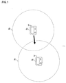
- Fig. 1 illustrates a communication system 1 according to an example of the present invention.
- the communication system 1 is comprised of a plurality of wireless communication terminal (hereinafter, simply referred to as "communication terminals").
- communication terminals two portable game devices 2a and 2b (generically referred to as game devices 2 as required) are illustrated as examples of the communication terminals.
- the number of game devices 2 is not limited to two. Three or more devices may be provided.
- Each of the game devices 2 is provided with a wireless communication function.
- a wireless ad hoc network is built by using a wireless LAN standard such as IEEE802.11b.
- the game device 2a has a communication range 3a and the game device 2b has a communication range 3b. It will be assumed that the communication range 3a is identical in size with the communication range 3b. In the illustrated state, the devices are not within the communication range of each other and therefore cannot recognize each other. When the game device 2b enters the communication range 3a as indicated by an arrow, the game device 2a simultaneously enters the communication range 3b so that communication can be established between the devices.
- the game device 2b To establish communication, it is necessary for the game device 2b to receive a beacon signal (broadcast signal) transmitted by the game device 2a.
- the game device 2b should respond to the signal by transmitting a request to participate in a network and the game device 2a should receive the request.
- a beacon signal broadcast signal
- the game device 2b should respond to the signal by transmitting a request to participate in a network and the game device 2a should receive the request.
- communication can be established in a short period of time by turning the power of the game devices 2 on under a mutual agreement, and by allowing one of the devices to respond to the beacon signal from the other with a request for participation.
- the user can start the game when a search upon power-on of the game device 2 immediately succeeds in finding a game partner.
- battery power consumption may be increased because the search time will be long to find a game partner.
- the game device 2 since the game device 2 is portable and used in a mobile environment, it might be able to enter communication with another game device at any moment. Accordingly, the game device 2 according to the example executes a search immediately upon power-on and enters a power-saving, standby mode when a game partner cannot be found in the search. In a standby mode, the game device 2 can expect to encounter a nearby game device while maintaining low power consumption. The user may enjoy playing a game in a single-player mode using the game device 2 in the standby mode.
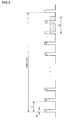
- Fig. 2 is a timing chart for a standby mode according to the example.
- the game device In the standby mode, the game device not only searches for a nearby terminal but also broadcasts its own presence. With this, evenwhen another communication terminal in the communication range is only executing a search, the game device can notify the the another communication terminal of its presence, making it possible to establish communication with the another communication terminal.
- Fig. 2 illustrates a case where both of the game devices 2a and 2b are executing the standby mode according to the example. Both of the game devices 2a and 2b are executing the standby mode before entering the communication range of each other.
- Fig. 2 illustrates the behavior of the devices when the game device 2b of Fig. 1 enters the communication range 3a of the game device 2a and the game device 2a simultaneously enters the communication range 3b of the game device 2b.
- the game device 2 is provided with a processor primarily performing an operation related to game processes and an air interface apparatus performing an operation related to communication.
- the standby mode is executed by the air interface apparatus. While the stand by mode is being executed, the user may enjoy a game alone. Alternatively, the supply of power to the processor may be suspended when the user does not play the game. Irrespective whether the user plays in a single-player mode, the user can benefit from power-saving in the standby mode by suspending the supply of power to the air interface apparatus as appropriate.
- a transmission mode in which a broadcast signal is transmitted a plurality of times and a reception mode in which a broadcast signal transmitted from another communication terminal is monitored are alternately executed.
- a combination of the transmission mode and the reception mode which are alternately executed constitutes a single cycle of the standby mode.
- periods of executing the transmission mode and the reception mode are preferably fixed to make it simple to control the execution of these modes.
- the transmission mode enables notifying the nearby communication terminal of the device's presence.
- the reception mode enables recognition of the presence of another nearby communication terminal.
- power saving is achieved by limiting the operation to simple ones.
- the standby mode As a whole.
- the transmission mode and the reception mode are executed in turn.
- the standby mode at least one cycle is repeated.
- a communication terminal transmits a beacon signal, a broadcast signal, at predetermined time intervals.
- the time interval may be set to, for example, 100msec.
- the air interface apparatus of the communication terminal transmits a beacon signal and immediately makes a transition from a running (operating) state to a power-saving state (sleep state). By reducing power consumption while a beacon signal is not transmitted, the battery is prevented from running down excessively.
- the air interface apparatus is caused to make a transition from the power saving state to the running state.
- the apparatus immediately makes a transition to the power saving state again.
- the transmission of a beacon signal and the transition between power states alternate repeatedly.
- the transmission of a beacon signal itself requires a period of time of approximately 500 ⁇ sec. Considering the time required for state transition of the air interface apparatus, a minimum of 1msec is only required between the start-up of the air interface apparatus and the termination of the operation thereof. Thus, as illustrated in Fig. 2, in a period of 100msec of a beacon transmission cycle (beacon interval), a power-saving state lasting 99msec is secured for each running state lasting 1msec. Accordingly, power consumption in the transmission mode is significantly reduced. As described above, in the transmission mode according to the example, the air interface apparatus of the communication terminal transits from a running state to a sleep state immediately after transmitting a beacon signal in order to save power consumption.
- the air interface apparatus After transiting to the sleep state, the air interface apparatus transits from the sleeping state to the running state when a beacon signal should be transmitted, that is, 99msec passes. In the transmission mode, the other processes except for the transmission of a beacon signal which consume a power of the air interface apparatus are not performed.
- the communication terminal monitors a beacon signal transmitted from another communication terminal for a predetermined period of time.
- the requirement for the monitoring period is that the duration thereof is longer than an interval between beacon signals transmitted from another communication terminal. It is preferable that the duration be as short as possible from the viewpoint of power consumption.
- the game device 2b is executing the same standby mode as the game device 2a.
- the beacon cycle of the game device 2a and the game device 2b is 100msec. Accordingly, the duration of monitoring period is required to be longer than the time interval between beacon signals transmitted from within the device, i.e. longer than 100msec.
- a minimum monitoring period may be set to a duration which is a sum of the beacon interval (100msec) and a time required for reception of a beacon signal.
- the monitoring period i. e. scan time
- the monitoring period is set to 150msec.
- the transmission mode and the reception mode are executed within a cycle. It is preferable that the time for execution of the transmission mode be longer than the time for execution of the reception mode. In the transmission mode, the apparatus is maintained in a power-saving state outside the period for transmission of a beacon signal. Therefore, power consumption is significantly reduced. In the reception mode, it is necessary to monitor a beacon signal for a predetermined period of time. Therefore, power consumed in the reception mode is larger than that of the transmission mode. Further, when the game devices 2a and 2b are executing the same standby mode as illustrated, overlapping of the periods for execution of the reception mode is unfavorable in that it leads to waste in consumed power. For the reasons stated above, it is preferable that the duration of the period for execution of the reception mode be short. In the example illustrated in Fig. 2, the transmission mode is executed for 19.8 seconds in an entire cycle of 20 seconds, while the reception mode is executed for 0.2 seconds. In the transmission mode, a total of 198 beacon signals are transmitted.
- the running period is 348msec, where the running period is the summation time in a single cycle of the standby mode in which the air interface apparatus maintains the running state.
- the time for execution of the reception mode affects the running period of the air interface apparatus in a cycle more significantly than that of the transmission mode since power saving control is applied in the transmission mode. Therefore, by reducing the time for execution of the reception mode as much as possible, the efficiency of power saving in the standby mode is increased.
- the game device 2 When a game device 2 recognizes a nearby terminal in the reception mode, the game device 2 terminates the standby mode and transits from the standby mode into the normal mode.
- the air apparatus of the game device 2 is set to an ordinary running state.
- the game device 2b first detects the presence of the game device 2a, terminates its standby mode and makes a transition to the normal mode.
- the game device 2b continues to transmit a beacon signal in the normal mode at intervals of 100msec.
- IEEE802.11b employs carrier Sense Multiple Access with Collision Avoidance (CSMA/CA) as an access control scheme in the MAC layer. Therefore, strictly speaking, when the protocol of IEEE802.11 is employed, the device is not allowed to transmit a beacon signal freely in the normal mode.
- CSMA/CA carrier Sense Multiple Access with Collision Avoidance
- the game device 2a When receiving a beacon signal in the reception mode, the game device 2a makes a transition to the normal mode. In the normal mode, the game device 2a accepts a response or a beacon signal from the other communication terminal for a predetermined period of time subsequent to the transmission of a beacon signal. When the game devices enter the normal mode, they are ready to receive a response or a beacon signal from the other party and establish communication.
- the game device 2b upon reception of a beacon signal from the game device 2a in the reception mode, acquires the SSID of the network formed by the game device 2a by referring to the beacon signal. With this, the game device 2b enters the normal mode so that it is capable of transmitting a request to participate in the network to the game device 2a as well as transmitting a beacon signal. Since the game device 2a is in the transmission mode, it cannot respond to the request for participation received from the game device 2b. Subsequently, upon receiving a beacon signal of the game device 2b in the reception mode, the game device 2a acquires the SSID of the network formed by the game device 2b by referring to the beacon signal.
- the game device 2a enters the normal mode and transmits a request for participation in the network to the game device 2b.
- the devices already have the knowledge of the SSID of each other's network. Therefore, mutual communication can be established upon a request for participation in the network from one device to the other.
- the game device 2b entering the normal mode in advance of the game device 2a may analyze the beacon signal received from the game device 2a and transmit a request for participation in the BSS of the game device 2a at intervals of 100msec.
- the game device 2a is capable of receiving a request for participation from the game device 2b. This will enable early establishment of communication between the game device 2a and the game device 2b.
- the period for monitoring a signal from another communication terminal in the reception mode may preferably be determined in consideration of delay in beacon signal transmission due to carrier sense.
- the monitoring period in the reception mode is set to last 150msec.
- the entirety of 200msec scheduled for the reception may be assigned to monitoring.
- the reception mode may be expanded to, for example, 300msec and the monitoring period may be set to a duration within the range of 300msec.
- the duration of monitoring period may preferably be set to a sum of a beacon interval and a minimum predetermined time with which the transmission of a beacon signal is delayed to allow for carrier sense. With this, the likelihood of the beacon signal being received successfully even when the transmission of a beacon signal is delayed is increased.
- the game device 2b in the normal mode receiving a beacon signal from the game device 2a does not transmit its own beacon signal for a predetermined minimum period of time. Accordingly, it is preferable to set a time in the game device 2a that elapses since the transmission of the last beacon signal in the transmission mode until the entry into the monitoring period to be slightly shorter than the time predetermined minimum period of time. With this, power is prevented from being wasted in the game device 2a.
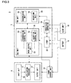
- Fig. 3 is a block diagram of the game device 2.
- the game device 2 is provided with a processor 4 for executing an operation related to game processes, and an air interface apparatus 5 for executing an operation related to communication.
- the game device 2 is further provided with a battery 16 for supplying power, a clock unit 18 for generating pulses at predetermined time intervals and a power control unit 30 for controlling power supplied to the processor 4.
- the processor 4 is provided with an input unit 10, an application processor 12 and an output unit 14.
- the air interface apparatus 5 is provided with a MAC unit 20, a timer unit 22, a power/clock controller 24 and a PHY unit 26.
- the MAC unit 20 is provided with a transmission control unit 50, a reception control unit 52 and a mode control unit 54.
- the PHY unit 26 is provided with a transmission unit 56 and a reception unit 58.
- Fig. 3 depicts function blocks implemented by the cooperation of the elements.
- the program may be built in the game device 2 or supplied from an external source in the form of a recording medium. Therefore, it will be obvious to those skilled in the art that the functional blocks may be implemented by a variety of manners including hardware only, software only or a combination of both.
- the input unit 10 comprises a group of buttons including an arrow key that accept commands from a user for operation.
- the application processor 12 runs a game application by referring to the command input via the input unit 10 and status information from another game device 2 received via the PHY unit 26.
- the output unit 14 comprises a display and a speaker etc. for output of the result of process in the applicationprocessor 12.
- the local status information processed in the application processor 12 is stored in a buffer in the MAC unit 20.
- the clock unit 18 supplies a clock to the timer 22 and the power/clock controller 24.
- the timer may be an independent element as illustrated.
- the timer 22 may be a function built in the MAC unit 20 or in the power/clock controller 24.
- the battery 16 supplies power to the power control unit 30, the timer 22 and the power/clock controller 24.
- the power control unit 30 controls power supply to the processor 4. As described above, the user may enjoy playing a game in a single-player mode using the game device 2 in the standby mode. In the standby mode, the battery 16 supplies power intermittently to the air interface apparatus 5. When the user plays a single-player game in the standby mode, the power control unit 30 supplies power to the processor 4.
- the MAC unit 20 transmits a request for suspension of power supply to the power control unit 30.
- the power control unit 30 suspends the supply of power to the processor 4 in the standby mode. With this, the processor 4 is turned off in the standby mode so that further power saving is achieved.
- the transmission control unit 50 of the MAC unit 20 is provided with the function of generating a beacon signal and analyzing a beacon signal received from another game device 2 via the PHY unit 26.
- the transmission unit 56 in the PHY unit 26 transmits a beacon signal to a nearby game device 2 and the reception unit 58 receives a beacon signal from another game device 2.
- the transmission control unit 50 controls the operation for transmission in the transmission unit 56 and the reception control unit 52 controls the operation for reception in the reception unit 58.
- the power/clock controller 24 controls the supply of power and clock to the MAC unit 20 and the PHY unit 26. More specifically, the power/clock controller 24 causes the MAC unit 20 and the PHY unit 26 to make a transition from a running state to a sleep state or from a sleep state to a running state.
- the transmission control unit 50 controls the transmission mode in which a broadcast signal is transmitted a plurality of times.
- the reception control unit 52 controls the reception mode in which a beacon signal transmitted from another game device 2 is monitored.
- the timing according to which the transmission control unit 50 executes the transmission mode and the timing according to which the reception control unit 52 executes the reception mode are controlled in accordance with an instruction supplied from the mode control unit 54.
- the mode control unit 54 receives a timing signal from the power/clock controller 24 and supplies an execution instruction to the transmission control unit 50 and the reception control unit 52 so that the transmission mode and the reception mode are executed alternately and cyclically.
- the mode control unit 54 sets the time for execution of the transmission mode to be longer than the time for execution of the reception mode.
- the transmission control unit 50 allows the transmission unit 56 to transmit a beacon signal in accordance with an execution instruction from the mode control unit 54.
- the power/clock controller 24 controls the transmission timing of the transmission unit 56.
- the power/clock controller 24 suspends power consumption in the MAC unit 20 and the PHY unit 26 by suspending the supply of clock to the MAC unit 20 and the PHY unit 26 to suspend their operation. With this, the MAC unit 20 and the PHY unit 26 enter a sleep state.
- the power/clock controller 24 sets the timer 22 so that the MAC unit 20 and the PHY unit 26 return to a running state after a predetermined period of time elapses since their entry into the sleep state.
- the beacon transmission cycle (beacon interval) is 100msec and the time required for transmission of beacon is 1msec. Therefore, the difference therebetween, i.e., 99msec, is set in the timer 22.
- the timer 22 counts pulses supplied from the clock unit 18 and supplies a wake signal to the power/clock controller 24 after the predetermined period of time (99msec) elapses.
- the power/clock controller 24 causes the MAC unit 20 and the PHY unit 26 to make a transition to a running state.
- the power/clock controller 24 repeats this control a predetermined number of times.
- the transmission control unit 50 transmits a beacon signal 198 times before terminating its control on the transmission mode.
- the mode control unit 54 directs the reception control unit 52 to enter the reception mode.
- the reception control unit 52 executes a search and analyzes the beacon signal received in the reception unit 58.
- the search time is set to 150msec.
- the mode control unit 54 directs the transmission control unit 50 to execute the transmission mode.
- the mode control unit 54 receives a timing signal from the power/clock controller 24 and controls the operating timing of the transmission control unit 50 and the reception control unit 52. The above cycle of standby mode is repeated.
- the mode control unit 54 may set an upper limit to the time for execution of the standby mode. For example, the mode control unit 54 may force termination of the standby mode unless a beacon signal is received from another communication terminal.
- the reception control unit 52 analyzes the beacon signal. For example, the reception control unit 52 may acquire an SSID included in the beacon signal and supplies the SSID acquired to the mode control unit 54. When receiving the SSID from the reception control unit 52, the mode control unit 54 recognizes that the search is successful. The mode control unit 54 then switches from the standby mode to the normal mode and supplies the SSID to the transmission control unit 50. Information like BSSID or BSSID-TYPE may be used to identify a network.
- the transmission control unit 50 transmits a beacon signal at predetermined beacon intervals and transmits a request for participation including the acquired SSID to the other communication terminal.
- the other game device 2 receives the beacon signal and enters the normal mode, communication with the other game device 2 is established when one of the game devices 2 receives from the other a request for participation in the network.
- the duration of monitoring period is set to be at least longer than the beacon interval and is preferably set to allow for carrier sense.
- the monitoring period may be calculated from target power consumption in the standby mode.
- Fig. 4 is a chart for explaining a method of determining a monitoring period (scan time) from target power consumption. The following parameters are defined in this method.
- T beacon interval
- Tb time required for making a transition from the power-saving state to the running state for beacon transmission and returning again to the power-saving state
- Ts monitoring period (scan time)
- Pt Power consumption per unit time in Tb
- Pr power consumption in a unit time during the scan
- Ps power consumption in a unit time in the power-saving state
- target average power consumption Pave per a unit time is calculated by the following equation.
- Pave Pt ⁇ Tb ( n - x ) nT + Pr ⁇ Ts nT + Ps ( nT - ( n - x ) Tb - Ts ) nT
- Tb is set to 1msec
- the relation between T and Ts is obtained by determining the target average power consumption Pave.
- the monitoring period Ts is determined.
- the communication terminal having made a transition from the standby mode to the normal mode may increase the intensity of signal transmission.
- the intensity of signal may be increased in order to establish communication successfully and to maintain stable communication.
- the duration of a cycle is set to 20 seconds in the example. Alternatively, the cycle may last for approximately 5 seconds or 1 minute.
- a beacon signal may contain a beacon ID.
- the number of beacon signals transmitted is predetermined. Therefore, the communication terminal first receiving a beacon signal can estimate the time which is required for a beacon signal transmitted from within the terminal to reach the terminal in communication.
Landscapes
- Engineering & Computer Science (AREA)
- Computer Networks & Wireless Communication (AREA)
- Signal Processing (AREA)
- Databases & Information Systems (AREA)
- Mobile Radio Communication Systems (AREA)
- Power Sources (AREA)
- Small-Scale Networks (AREA)
- Transceivers (AREA)
- Circuits Of Receivers In General (AREA)
Applications Claiming Priority (1)
| Application Number | Priority Date | Filing Date | Title |
|---|---|---|---|
| JP2004224779A JP4007982B2 (ja) | 2004-07-30 | 2004-07-30 | 通信端末装置、通信を確立するための方法およびゲーム装置 |
Publications (3)
| Publication Number | Publication Date |
|---|---|
| EP1622319A2 true EP1622319A2 (de) | 2006-02-01 |
| EP1622319A3 EP1622319A3 (de) | 2006-09-27 |
| EP1622319B1 EP1622319B1 (de) | 2013-04-03 |
Family
ID=35432510
Family Applications (1)
| Application Number | Title | Priority Date | Filing Date |
|---|---|---|---|
| EP20050254678 Expired - Lifetime EP1622319B1 (de) | 2004-07-30 | 2005-07-27 | Kommunikationsendgerät und Verfahren zum Kommunikationsaufbau |
Country Status (5)
| Country | Link |
|---|---|
| US (1) | US7535881B2 (de) |
| EP (1) | EP1622319B1 (de) |
| JP (1) | JP4007982B2 (de) |
| KR (1) | KR101258846B1 (de) |
| CN (1) | CN1728669A (de) |
Cited By (4)
| Publication number | Priority date | Publication date | Assignee | Title |
|---|---|---|---|---|
| EP2422855A1 (de) * | 2010-07-07 | 2012-02-29 | Nintendo Co., Ltd. | Informationsverarbeitungsprogramm, Informationsverarbeitungssystem und Informationsverarbeitungsverfahren |
| US8233456B1 (en) | 2006-10-16 | 2012-07-31 | Marvell International Ltd. | Power save mechanisms for dynamic ad-hoc networks |
| US8619623B2 (en) | 2006-08-08 | 2013-12-31 | Marvell World Trade Ltd. | Ad-hoc simple configuration |
| US9444874B2 (en) | 2006-10-16 | 2016-09-13 | Marvell International Ltd. | Automatic Ad-Hoc network creation and coalescing using WPS |
Families Citing this family (35)
| Publication number | Priority date | Publication date | Assignee | Title |
|---|---|---|---|---|
| JP3698711B1 (ja) * | 2004-05-07 | 2005-09-21 | 株式会社ソニー・コンピュータエンタテインメント | ネットワーク識別子設定方法、通信方法および無線通信端末装置 |
| KR100713145B1 (ko) * | 2005-02-18 | 2007-05-02 | 삼성전자주식회사 | 무선 센서 네트워크에서의 전력소모를 최소화하는 네트워크형성방법 |
| US7697896B2 (en) * | 2005-03-16 | 2010-04-13 | Sony Computer Entertainment Inc. | Communication apparatus preventing communication interference |
| KR100725406B1 (ko) * | 2005-09-26 | 2007-06-07 | 삼성전자주식회사 | 다수의 전력 절약 모드를 가지는 무선 통신 장치에서리스닝 구간을 조절하여 전력을 절약하는 방법 및 장치 |
| US8811369B2 (en) * | 2006-01-11 | 2014-08-19 | Qualcomm Incorporated | Methods and apparatus for supporting multiple communications modes of operation |
| EP1977563B1 (de) | 2006-01-11 | 2018-01-03 | QUALCOMM Incorporated | Codierung von bakensignalen zur identifikationsbereitstellung bei der peer-to-peer-kommunikation |
| JP4645479B2 (ja) * | 2006-02-28 | 2011-03-09 | パナソニック株式会社 | 無線装置及びプログラム |
| JP4762007B2 (ja) * | 2006-03-03 | 2011-08-31 | パナソニック株式会社 | 中継装置、通信端末、及び通信システム |
| JP5255196B2 (ja) * | 2006-10-19 | 2013-08-07 | 任天堂株式会社 | ゲーム機、無線モジュール、ゲームシステムおよびゲーム処理方法 |
| US9308455B1 (en) | 2006-10-25 | 2016-04-12 | Marvell International Ltd. | System and method for gaming in an ad-hoc network |
| US8628420B2 (en) | 2007-07-03 | 2014-01-14 | Marvell World Trade Ltd. | Location aware ad-hoc gaming |
| CA2676046C (en) * | 2007-08-31 | 2012-07-10 | Newtrax Technologies Inc. | Tracking of and communication with mobile terminals using a battery-powered wireless network infrastructure |
| CA2599471A1 (en) * | 2007-08-31 | 2009-02-28 | Alexandre Cervinka | Underground communication network system for personal tracking and hvac control |
| US8595501B2 (en) * | 2008-05-09 | 2013-11-26 | Qualcomm Incorporated | Network helper for authentication between a token and verifiers |
| JP4585582B2 (ja) | 2008-07-24 | 2010-11-24 | 株式会社東芝 | 通信装置および通信制御方法 |
| US10953323B2 (en) | 2008-11-17 | 2021-03-23 | Sony Interactive Entertainment Inc. | Radio communication terminal, method for controlling the same, and information storage medium |
| WO2012035764A1 (ja) | 2010-09-15 | 2012-03-22 | 株式会社ソニー・コンピュータエンタテインメント | 無線通信装置、無線通信システムおよびチャネルの切替方法 |
| JP5296148B2 (ja) | 2011-07-04 | 2013-09-25 | 株式会社ソニー・コンピュータエンタテインメント | 携帯通信端末 |
| US9137727B2 (en) * | 2012-03-30 | 2015-09-15 | Hewlett-Packard Development Company, L.P. | Controlled client roaming |
| JP2014027421A (ja) * | 2012-07-25 | 2014-02-06 | Toshiba Corp | 通信端末および通信方法 |
| CN102903198B (zh) * | 2012-10-16 | 2016-09-07 | 慧翰微电子股份有限公司 | 一种防丢器及应用其的防丢方法 |
| EP2768271A1 (de) * | 2013-02-15 | 2014-08-20 | Alcatel Lucent | Funkverbindungsaufbau |
| CN103795464B (zh) * | 2013-07-31 | 2015-04-15 | 深圳光启创新技术有限公司 | 具有错误重发机制的可见光信号的发送方法和接收方法、装置及系统 |
| JP6269033B2 (ja) * | 2013-12-20 | 2018-01-31 | カシオ計算機株式会社 | 通信端末、通信制御方法及びプログラム |
| WO2015153352A1 (en) * | 2014-03-31 | 2015-10-08 | Yext, Inc. | Beacon device for enhancing measurements of the effecitiveness of mobile notifications |
| JP2015133737A (ja) * | 2015-03-05 | 2015-07-23 | 株式会社東芝 | 通信端末および通信方法 |
| CN106205005B (zh) * | 2016-08-29 | 2018-11-27 | 青岛歌尔声学科技有限公司 | 一种预警方法和一种预警装置 |
| TWM568972U (zh) | 2016-10-31 | 2018-10-21 | 美商米沃奇電子工具公司 | 發訊系統及位置紀錄系統 |
| JP2018018530A (ja) * | 2017-08-29 | 2018-02-01 | カシオ計算機株式会社 | 通信装置、通信方法、及びプログラム |
| CN109873674B (zh) * | 2017-12-05 | 2021-11-16 | 佛山市顺德区美的电热电器制造有限公司 | 电器的匹配方法、匹配系统与加热平台 |
| US11206412B2 (en) * | 2018-02-20 | 2021-12-21 | Netgear, Inc. | Band steering for a low power device |
| US10813169B2 (en) | 2018-03-22 | 2020-10-20 | GoTenna, Inc. | Mesh network deployment kit |
| EP3671667A1 (de) * | 2018-12-18 | 2020-06-24 | Neopost Technologies | Gesichertes paketschliessfachsystem mit token-sicherheit |
| CN114223224B (zh) | 2019-08-13 | 2024-03-08 | 米沃奇电动工具公司 | 具有多个和应用程序可设置的信标发射率的工具追踪装置 |
| CN112601273A (zh) * | 2020-12-07 | 2021-04-02 | 深圳市福日中诺电子科技有限公司 | 根据通信模式动态调整射频发射开关的方法及终端 |
Citations (1)
| Publication number | Priority date | Publication date | Assignee | Title |
|---|---|---|---|---|
| WO2004038938A1 (en) | 2002-10-24 | 2004-05-06 | Koninklijke Philips Electronics N.V. | Beacon channel for frequency hopping wireless devices |
Family Cites Families (12)
| Publication number | Priority date | Publication date | Assignee | Title |
|---|---|---|---|---|
| JPH02186844A (ja) | 1989-01-13 | 1990-07-23 | Iwatsu Electric Co Ltd | 移動体通信の通信方法 |
| JPH04359176A (ja) | 1991-06-04 | 1992-12-11 | Fujitsu Ltd | ビーコン送信機 |
| US5618045A (en) * | 1995-02-08 | 1997-04-08 | Kagan; Michael | Interactive multiple player game system and method of playing a game between at least two players |
| JP3672963B2 (ja) * | 1995-03-31 | 2005-07-20 | 株式会社東海理化電機製作所 | 送受信システム |
| JPH09233542A (ja) | 1996-02-20 | 1997-09-05 | Toyoki Sasakura | 機器の使用制限装置及び携帯電話機 |
| DE69930918T2 (de) * | 1999-01-25 | 2006-11-30 | International Business Machines Corp. | Dienstankündigungen in drahtlosen lokalen Netzen |
| KR100416263B1 (ko) | 2001-11-30 | 2004-01-31 | 삼성전자주식회사 | 비콘간격의 조절이 가능한 무선통신기기 및 그 방법 |
| JP3876752B2 (ja) | 2002-04-15 | 2007-02-07 | ソニー株式会社 | 通信システム、通信制御装置及び通信制御方法、並びにコンピュータ・プログラム |
| US7260357B2 (en) * | 2002-04-17 | 2007-08-21 | Broadcom Corporation | Bluetooth fast connection mode for wireless peripheral device |
| JP2004032552A (ja) | 2002-06-27 | 2004-01-29 | Uniden Corp | 通信端末装置、通信システム及びプログラム |
| JP2004080400A (ja) | 2002-08-19 | 2004-03-11 | Matsushita Electric Ind Co Ltd | 自動ロール決定システム |
| JP4073885B2 (ja) * | 2003-06-17 | 2008-04-09 | 任天堂株式会社 | ゲームシステム、ゲーム装置およびゲームプログラム |
-
2004
- 2004-07-30 JP JP2004224779A patent/JP4007982B2/ja not_active Expired - Lifetime
-
2005
- 2005-07-27 EP EP20050254678 patent/EP1622319B1/de not_active Expired - Lifetime
- 2005-07-27 KR KR1020050068363A patent/KR101258846B1/ko not_active Expired - Lifetime
- 2005-07-29 US US11/194,135 patent/US7535881B2/en active Active
- 2005-08-01 CN CNA2005100878623A patent/CN1728669A/zh active Pending
Patent Citations (1)
| Publication number | Priority date | Publication date | Assignee | Title |
|---|---|---|---|---|
| WO2004038938A1 (en) | 2002-10-24 | 2004-05-06 | Koninklijke Philips Electronics N.V. | Beacon channel for frequency hopping wireless devices |
Cited By (6)
| Publication number | Priority date | Publication date | Assignee | Title |
|---|---|---|---|---|
| US8619623B2 (en) | 2006-08-08 | 2013-12-31 | Marvell World Trade Ltd. | Ad-hoc simple configuration |
| US9019866B2 (en) | 2006-08-08 | 2015-04-28 | Marvell World Trade Ltd. | Ad-hoc simple configuration |
| US8233456B1 (en) | 2006-10-16 | 2012-07-31 | Marvell International Ltd. | Power save mechanisms for dynamic ad-hoc networks |
| US9374785B1 (en) | 2006-10-16 | 2016-06-21 | Marvell International Ltd. | Power save mechanisms for dynamic ad-hoc networks |
| US9444874B2 (en) | 2006-10-16 | 2016-09-13 | Marvell International Ltd. | Automatic Ad-Hoc network creation and coalescing using WPS |
| EP2422855A1 (de) * | 2010-07-07 | 2012-02-29 | Nintendo Co., Ltd. | Informationsverarbeitungsprogramm, Informationsverarbeitungssystem und Informationsverarbeitungsverfahren |
Also Published As
| Publication number | Publication date |
|---|---|
| KR20060048811A (ko) | 2006-05-18 |
| US20060034315A1 (en) | 2006-02-16 |
| EP1622319A3 (de) | 2006-09-27 |
| JP2006050020A (ja) | 2006-02-16 |
| CN1728669A (zh) | 2006-02-01 |
| KR101258846B1 (ko) | 2013-05-03 |
| EP1622319B1 (de) | 2013-04-03 |
| JP4007982B2 (ja) | 2007-11-14 |
| US7535881B2 (en) | 2009-05-19 |
Similar Documents
| Publication | Publication Date | Title |
|---|---|---|
| EP1622319B1 (de) | Kommunikationsendgerät und Verfahren zum Kommunikationsaufbau | |
| JP7275221B2 (ja) | スリープ状態にあるアクセサリの低電力でのアクティブ化 | |
| KR101650118B1 (ko) | 액세스 포인트들을 위한 전력 절감 모드 | |
| US9042282B2 (en) | Wireless communication device, wireless communication system, and channel switching method | |
| JP3877722B2 (ja) | 通信方法、通信端末装置および通信システム | |
| EP1587242B1 (de) | Kommunikationsterminal, verfahren, programm und system zur erweiterten energieeinsparung | |
| CN105453151A (zh) | 具有wlan能力的远程控制设备 | |
| JP2008061111A (ja) | 電子機器および無線通信制御方法 | |
| JP7277109B2 (ja) | 通信装置、制御方法、及びプログラム | |
| JP5584582B2 (ja) | 通信装置、通信装置の制御方法、およびプログラム |
Legal Events
| Date | Code | Title | Description |
|---|---|---|---|
| PUAI | Public reference made under article 153(3) epc to a published international application that has entered the european phase |
Free format text: ORIGINAL CODE: 0009012 |
|
| AK | Designated contracting states |
Kind code of ref document: A2 Designated state(s): AT BE BG CH CY CZ DE DK EE ES FI FR GB GR HU IE IS IT LI LT LU LV MC NL PL PT RO SE SI SK TR |
|
| AX | Request for extension of the european patent |
Extension state: AL BA HR MK YU |
|
| PUAL | Search report despatched |
Free format text: ORIGINAL CODE: 0009013 |
|
| AK | Designated contracting states |
Kind code of ref document: A3 Designated state(s): AT BE BG CH CY CZ DE DK EE ES FI FR GB GR HU IE IS IT LI LT LU LV MC NL PL PT RO SE SI SK TR |
|
| AX | Request for extension of the european patent |
Extension state: AL BA HR MK YU |
|
| 17P | Request for examination filed |
Effective date: 20070320 |
|
| AKX | Designation fees paid |
Designated state(s): AT BE BG CH CY CZ DE DK EE ES FI FR GB GR HU IE IS IT LI LT LU LV MC NL PL PT RO SE SI SK TR |
|
| 17Q | First examination report despatched |
Effective date: 20070628 |
|
| REG | Reference to a national code |
Ref country code: DE Ref legal event code: R079 Ref document number: 602005038867 Country of ref document: DE Free format text: PREVIOUS MAIN CLASS: H04L0012280000 Ipc: H04W0008000000 |
|
| GRAP | Despatch of communication of intention to grant a patent |
Free format text: ORIGINAL CODE: EPIDOSNIGR1 |
|
| RIC1 | Information provided on ipc code assigned before grant |
Ipc: H04W 8/00 20090101AFI20121119BHEP Ipc: H04W 52/02 20090101ALN20121119BHEP Ipc: H04W 76/02 20090101ALN20121119BHEP |
|
| RIN1 | Information on inventor provided before grant (corrected) |
Inventor name: TANIGUCHI, KAZUSHIGE, Inventor name: MAEKAWA, ITARU, |
|
| GRAS | Grant fee paid |
Free format text: ORIGINAL CODE: EPIDOSNIGR3 |
|
| GRAA | (expected) grant |
Free format text: ORIGINAL CODE: 0009210 |
|
| AK | Designated contracting states |
Kind code of ref document: B1 Designated state(s): AT BE BG CH CY CZ DE DK EE ES FI FR GB GR HU IE IS IT LI LT LU LV MC NL PL PT RO SE SI SK TR |
|
| REG | Reference to a national code |
Ref country code: GB Ref legal event code: FG4D |
|
| REG | Reference to a national code |
Ref country code: CH Ref legal event code: EP Ref country code: AT Ref legal event code: REF Ref document number: 605384 Country of ref document: AT Kind code of ref document: T Effective date: 20130415 |
|
| REG | Reference to a national code |
Ref country code: IE Ref legal event code: FG4D |
|
| REG | Reference to a national code |
Ref country code: DE Ref legal event code: R096 Ref document number: 602005038867 Country of ref document: DE Effective date: 20130529 |
|
| RAP2 | Party data changed (patent owner data changed or rights of a patent transferred) |
Owner name: SONY COMPUTER ENTERTAINMENT INCORPORATED |
|
| RAP2 | Party data changed (patent owner data changed or rights of a patent transferred) |
Owner name: SONY COMPUTER ENTERTAINMENT INC. |
|
| REG | Reference to a national code |
Ref country code: AT Ref legal event code: MK05 Ref document number: 605384 Country of ref document: AT Kind code of ref document: T Effective date: 20130403 |
|
| PG25 | Lapsed in a contracting state [announced via postgrant information from national office to epo] |
Ref country code: SI Free format text: LAPSE BECAUSE OF FAILURE TO SUBMIT A TRANSLATION OF THE DESCRIPTION OR TO PAY THE FEE WITHIN THE PRESCRIBED TIME-LIMIT Effective date: 20130403 |
|
| REG | Reference to a national code |
Ref country code: NL Ref legal event code: VDEP Effective date: 20130403 |
|
| REG | Reference to a national code |
Ref country code: LT Ref legal event code: MG4D |
|
| PG25 | Lapsed in a contracting state [announced via postgrant information from national office to epo] |
Ref country code: FI Free format text: LAPSE BECAUSE OF FAILURE TO SUBMIT A TRANSLATION OF THE DESCRIPTION OR TO PAY THE FEE WITHIN THE PRESCRIBED TIME-LIMIT Effective date: 20130403 Ref country code: LT Free format text: LAPSE BECAUSE OF FAILURE TO SUBMIT A TRANSLATION OF THE DESCRIPTION OR TO PAY THE FEE WITHIN THE PRESCRIBED TIME-LIMIT Effective date: 20130403 Ref country code: IS Free format text: LAPSE BECAUSE OF FAILURE TO SUBMIT A TRANSLATION OF THE DESCRIPTION OR TO PAY THE FEE WITHIN THE PRESCRIBED TIME-LIMIT Effective date: 20130803 Ref country code: ES Free format text: LAPSE BECAUSE OF FAILURE TO SUBMIT A TRANSLATION OF THE DESCRIPTION OR TO PAY THE FEE WITHIN THE PRESCRIBED TIME-LIMIT Effective date: 20130714 Ref country code: PT Free format text: LAPSE BECAUSE OF FAILURE TO SUBMIT A TRANSLATION OF THE DESCRIPTION OR TO PAY THE FEE WITHIN THE PRESCRIBED TIME-LIMIT Effective date: 20130805 Ref country code: GR Free format text: LAPSE BECAUSE OF FAILURE TO SUBMIT A TRANSLATION OF THE DESCRIPTION OR TO PAY THE FEE WITHIN THE PRESCRIBED TIME-LIMIT Effective date: 20130704 Ref country code: NL Free format text: LAPSE BECAUSE OF FAILURE TO SUBMIT A TRANSLATION OF THE DESCRIPTION OR TO PAY THE FEE WITHIN THE PRESCRIBED TIME-LIMIT Effective date: 20130403 Ref country code: AT Free format text: LAPSE BECAUSE OF FAILURE TO SUBMIT A TRANSLATION OF THE DESCRIPTION OR TO PAY THE FEE WITHIN THE PRESCRIBED TIME-LIMIT Effective date: 20130403 Ref country code: BE Free format text: LAPSE BECAUSE OF FAILURE TO SUBMIT A TRANSLATION OF THE DESCRIPTION OR TO PAY THE FEE WITHIN THE PRESCRIBED TIME-LIMIT Effective date: 20130403 Ref country code: SE Free format text: LAPSE BECAUSE OF FAILURE TO SUBMIT A TRANSLATION OF THE DESCRIPTION OR TO PAY THE FEE WITHIN THE PRESCRIBED TIME-LIMIT Effective date: 20130403 |
|
| PG25 | Lapsed in a contracting state [announced via postgrant information from national office to epo] |
Ref country code: LV Free format text: LAPSE BECAUSE OF FAILURE TO SUBMIT A TRANSLATION OF THE DESCRIPTION OR TO PAY THE FEE WITHIN THE PRESCRIBED TIME-LIMIT Effective date: 20130403 Ref country code: PL Free format text: LAPSE BECAUSE OF FAILURE TO SUBMIT A TRANSLATION OF THE DESCRIPTION OR TO PAY THE FEE WITHIN THE PRESCRIBED TIME-LIMIT Effective date: 20130403 Ref country code: BG Free format text: LAPSE BECAUSE OF FAILURE TO SUBMIT A TRANSLATION OF THE DESCRIPTION OR TO PAY THE FEE WITHIN THE PRESCRIBED TIME-LIMIT Effective date: 20130703 Ref country code: CY Free format text: LAPSE BECAUSE OF FAILURE TO SUBMIT A TRANSLATION OF THE DESCRIPTION OR TO PAY THE FEE WITHIN THE PRESCRIBED TIME-LIMIT Effective date: 20130403 |
|
| PG25 | Lapsed in a contracting state [announced via postgrant information from national office to epo] |
Ref country code: SK Free format text: LAPSE BECAUSE OF FAILURE TO SUBMIT A TRANSLATION OF THE DESCRIPTION OR TO PAY THE FEE WITHIN THE PRESCRIBED TIME-LIMIT Effective date: 20130403 Ref country code: DK Free format text: LAPSE BECAUSE OF FAILURE TO SUBMIT A TRANSLATION OF THE DESCRIPTION OR TO PAY THE FEE WITHIN THE PRESCRIBED TIME-LIMIT Effective date: 20130403 Ref country code: EE Free format text: LAPSE BECAUSE OF FAILURE TO SUBMIT A TRANSLATION OF THE DESCRIPTION OR TO PAY THE FEE WITHIN THE PRESCRIBED TIME-LIMIT Effective date: 20130403 Ref country code: CZ Free format text: LAPSE BECAUSE OF FAILURE TO SUBMIT A TRANSLATION OF THE DESCRIPTION OR TO PAY THE FEE WITHIN THE PRESCRIBED TIME-LIMIT Effective date: 20130403 |
|
| PLBE | No opposition filed within time limit |
Free format text: ORIGINAL CODE: 0009261 |
|
| STAA | Information on the status of an ep patent application or granted ep patent |
Free format text: STATUS: NO OPPOSITION FILED WITHIN TIME LIMIT |
|
| PG25 | Lapsed in a contracting state [announced via postgrant information from national office to epo] |
Ref country code: RO Free format text: LAPSE BECAUSE OF FAILURE TO SUBMIT A TRANSLATION OF THE DESCRIPTION OR TO PAY THE FEE WITHIN THE PRESCRIBED TIME-LIMIT Effective date: 20130403 Ref country code: MC Free format text: LAPSE BECAUSE OF FAILURE TO SUBMIT A TRANSLATION OF THE DESCRIPTION OR TO PAY THE FEE WITHIN THE PRESCRIBED TIME-LIMIT Effective date: 20130403 Ref country code: IT Free format text: LAPSE BECAUSE OF FAILURE TO SUBMIT A TRANSLATION OF THE DESCRIPTION OR TO PAY THE FEE WITHIN THE PRESCRIBED TIME-LIMIT Effective date: 20130403 |
|
| REG | Reference to a national code |
Ref country code: CH Ref legal event code: PL |
|
| 26N | No opposition filed |
Effective date: 20140106 |
|
| REG | Reference to a national code |
Ref country code: DE Ref legal event code: R097 Ref document number: 602005038867 Country of ref document: DE Effective date: 20140106 |
|
| REG | Reference to a national code |
Ref country code: IE Ref legal event code: MM4A |
|
| PG25 | Lapsed in a contracting state [announced via postgrant information from national office to epo] |
Ref country code: LI Free format text: LAPSE BECAUSE OF NON-PAYMENT OF DUE FEES Effective date: 20130731 Ref country code: CH Free format text: LAPSE BECAUSE OF NON-PAYMENT OF DUE FEES Effective date: 20130731 |
|
| PG25 | Lapsed in a contracting state [announced via postgrant information from national office to epo] |
Ref country code: IE Free format text: LAPSE BECAUSE OF NON-PAYMENT OF DUE FEES Effective date: 20130727 |
|
| PG25 | Lapsed in a contracting state [announced via postgrant information from national office to epo] |
Ref country code: TR Free format text: LAPSE BECAUSE OF FAILURE TO SUBMIT A TRANSLATION OF THE DESCRIPTION OR TO PAY THE FEE WITHIN THE PRESCRIBED TIME-LIMIT Effective date: 20130403 |
|
| PG25 | Lapsed in a contracting state [announced via postgrant information from national office to epo] |
Ref country code: LU Free format text: LAPSE BECAUSE OF NON-PAYMENT OF DUE FEES Effective date: 20130727 Ref country code: HU Free format text: LAPSE BECAUSE OF FAILURE TO SUBMIT A TRANSLATION OF THE DESCRIPTION OR TO PAY THE FEE WITHIN THE PRESCRIBED TIME-LIMIT; INVALID AB INITIO Effective date: 20050727 |
|
| REG | Reference to a national code |
Ref country code: FR Ref legal event code: PLFP Year of fee payment: 12 |
|
| REG | Reference to a national code |
Ref country code: FR Ref legal event code: PLFP Year of fee payment: 13 |
|
| REG | Reference to a national code |
Ref country code: FR Ref legal event code: PLFP Year of fee payment: 14 |
|
| REG | Reference to a national code |
Ref country code: DE Ref legal event code: R082 Ref document number: 602005038867 Country of ref document: DE Representative=s name: D YOUNG & CO LLP, DE |
|
| P01 | Opt-out of the competence of the unified patent court (upc) registered |
Effective date: 20230519 |
|
| PGFP | Annual fee paid to national office [announced via postgrant information from national office to epo] |
Ref country code: GB Payment date: 20240620 Year of fee payment: 20 |
|
| PGFP | Annual fee paid to national office [announced via postgrant information from national office to epo] |
Ref country code: FR Payment date: 20240619 Year of fee payment: 20 |
|
| PGFP | Annual fee paid to national office [announced via postgrant information from national office to epo] |
Ref country code: DE Payment date: 20240619 Year of fee payment: 20 |
|
| REG | Reference to a national code |
Ref country code: DE Ref legal event code: R071 Ref document number: 602005038867 Country of ref document: DE |
|
| REG | Reference to a national code |
Ref country code: GB Ref legal event code: PE20 Expiry date: 20250726 |