EP1622732B1 - Machine a fabriquer des ressorts helicoidaux et procede de commande de ladite machine - Google Patents
Machine a fabriquer des ressorts helicoidaux et procede de commande de ladite machine Download PDFInfo
- Publication number
- EP1622732B1 EP1622732B1 EP04731869A EP04731869A EP1622732B1 EP 1622732 B1 EP1622732 B1 EP 1622732B1 EP 04731869 A EP04731869 A EP 04731869A EP 04731869 A EP04731869 A EP 04731869A EP 1622732 B1 EP1622732 B1 EP 1622732B1
- Authority
- EP
- European Patent Office
- Prior art keywords
- measuring
- spring
- wire
- control
- winding machine
- Prior art date
- Legal status (The legal status is an assumption and is not a legal conclusion. Google has not performed a legal analysis and makes no representation as to the accuracy of the status listed.)
- Expired - Lifetime
Links
Images

Classifications
-
- B—PERFORMING OPERATIONS; TRANSPORTING
- B21—MECHANICAL METAL-WORKING WITHOUT ESSENTIALLY REMOVING MATERIAL; PUNCHING METAL
- B21C—MANUFACTURE OF METAL SHEETS, WIRE, RODS, TUBES, PROFILES OR LIKE SEMI-MANUFACTURED PRODUCTS OTHERWISE THAN BY ROLLING; AUXILIARY OPERATIONS USED IN CONNECTION WITH METAL-WORKING WITHOUT ESSENTIALLY REMOVING MATERIAL
- B21C51/00—Measuring, gauging, indicating, counting, or marking devices specially adapted for use in the production or manipulation of material in accordance with subclasses B21B - B21F
-
- B—PERFORMING OPERATIONS; TRANSPORTING
- B21—MECHANICAL METAL-WORKING WITHOUT ESSENTIALLY REMOVING MATERIAL; PUNCHING METAL
- B21F—WORKING OR PROCESSING OF METAL WIRE
- B21F3/00—Coiling wire into particular forms
- B21F3/02—Coiling wire into particular forms helically
Definitions
- the invention relates to a spring coiling machine and a method for controlling a spring coiling machine according to the preamble of claims 1 and 5.
- a machine and such a method are known from US 5,865,051 known.
- spring winding machines as used for example for the production of tortuous springs such as mattress and upholstery springs, technical tension and compression springs and torsion springs of any shape, provided that they have at least one tortuous body, spring wire is usually by means of a conveyor of a reel withdrawn and fed to a forming device.
- the forming device may comprise one or more winding tools, which deflect the spring wire during advancement and thereby transform into a spring.
- the winding tools can be firmly and immovably connected to the machine during the spring production process or can be held movably on the machine. In the latter case, the movement of the tools, for example, by a rotatable cam or by a servo motor and / or a piezotranslator.
- the properties of the produced springs may deviate more or less from the desired nominal properties.
- material properties such as wire diameter, warping or twisting, composition of the mixed structure, internal stresses or microcracks can affect the tensile strength, the modulus of elasticity or other properties affecting the ductility of the wire.
- Due to inhomogeneities of the wire and its electrical properties such as the conductivity or impedance or permeability within the wire may be different at different positions.
- the material inhomogeneities can lead to the properties of the produced springs not being constant.
- shape parameters such as e.g. Coil diameter, pitch, etc., and / or mechanical properties, e.g. the spring constants have considerable bandwidths. The production of geometrically accurate springs with properties within close tolerance limits is often difficult.
- An adaptive spring winding apparatus in which means for improving the constancy of the spring characteristics are provided. Downstream there are after the forming tool Device for monitoring the wire and for generating output signals which are characteristic of the physical characteristics of the bent wire. The output signals are supplied to the controller and used by the latter for fine positioning of the forming tool or of its position, in such a way that the outer diameter or the inner diameter of the springs is maintained.
- a disadvantage of this spring winding device is that the influence of different wire properties on physical properties of the spring to be produced are detected only during or after the forming process. Only after the measurement of inner diameters or outside diameters, which deviate from the nominal values, the control can be made to a position correction of the winding tools. It must be expected that springs are produced time and again, whose spring characteristics differ from the desired spring properties. If tight tolerances are to be met, such springs must be sorted out.
- This object is achieved by a spring coiling machine with a measuring device and by a method for producing springs according to the features of patent claims 1 and 5.
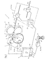
- FIG. 1 schematically shows a schematic diagram with parts of a spring coiling machine 1, which are of importance for the invention.
- the spring coiling machine 1 comprises an electronic machine control, called control 3 for short, a wire conveyor 5 with two wire feed rollers 5a, 5b, a wire former 7 having a feed part 9 comprising two support rollers 9a, 9b or a feedstock (not shown) and at least one converter 11 Controller 3 may include one or more components.
- the controller 3 may comprise a conventional machine controller and a PC or industrial computer connected thereto.
- FIG. 1 As shown embodiment of the invention are as a converter 11, a bender 11a for deflecting a spring wire, short wire 13 called in the radial direction or for forming the turns of a screw or
- Mattress spring and a deflector 11b for deflecting the wire 13 in the axial direction or for forming the pitch of the spring 15 is provided.
- the conveying direction of the wire 13 is indicated by an arrow P.
- the position and / or position of the bender 11a and the deflector 11b are via actuators, for example via actuators, stepper or servo motors with or without gear or linear motors, which may include, for example, piezoelectric translators or electric motor or pneumatically driven spindles, and controllable.
- the means 11, 11a, 11b for deforming the wire 13 to a spring 15 are adjustable depending on the configuration of the spring coiling machine 1 before and / or after and / or during the manufacture of a spring 15 by the controller 3, controllable or adjustable.
- the processing cycle or drive intervals for the updating of the position or position of the converters 11 are short and, for example, in the range of a few milliseconds to about 100 ms.
- the controller 3 comprises means for detecting input or measured variables, for example a user interface 17 with a screen display 19 and a keyboard 21 and / or a device interface 23 for connecting measuring devices 25 and / or programming or data reading devices such as, for example for inputting setpoints or default functions for the control of the converter 11 are required.
- Connected measuring device 25a for detecting wire properties comprises a measuring sensor 27 which is arranged upstream of the wire-forming machine 7 so that it can detect wire properties prior to the deformation of the wire 13 into a spring 15.
- the measuring sensor 27 can be designed to detect a wide variety of material parameters or properties of the wire 13 with any desired measuring methods. It is also possible to use a plurality of measuring sensors 27 for detecting such measured quantities.
- the first measuring device 25a comprises an eddy current measuring device, as offered, for example, by the company IBG sketcher GmbH in Germany under the brand name eddyliner® and the type designation P or Px. Devices of this type are generally used in the field of material testing and quality assurance.
- the device comprises an evaluation unit 29 and as a measuring sensor 27 a coil connected thereto.
- a further coil with a piece of reference wire 13a may be connected to the evaluation unit 29 as a reference sensor 31.
- the evaluation unit 29 controls the measuring sensor 27 sequentially with a sequence of several different frequencies in the range of about 5Hz to about 300kHz.
- the control is carried out with a sinusoidal signal.
- the drive signal may also be a superposition of different sinusoidal signals.
- the control can be carried out continuously or in the form of pulse packets.
- the evaluation unit 29 determines, for example, from the attenuation behavior of the signals and / or from other measured variables that can be influenced by these signals at several or all measurement frequencies f i, the real part R i and the imaginary part I i of the impedance Z, where the index i is an integer value between one and can take eight, for example.
- the impedance Z could also be detected, which can be influenced by the damping behavior of the excitation signals or by induction or eddy currents which are generated by the excitation signals.
- the scale on the ordinate indicates normalized values with respect to a reference value of the impedance.
- the real and imaginary parts of the impedance values determined for certain measuring frequencies f i and for the designated WA, WB, WC and WD wires accept 13 characteristic values. These values correspond to a fingerprint of the respective wire 13, which can be determined by different properties such as chemical composition, structure of the structure, internal mechanical stresses, surface treatment, electrical conductivity, permeability, temperature, external diameter, shape of the cross-sectional area, etc.
- the inner or outer diameter of a coil spring may be too small or too large and / or the pitch of the spring 15 may differ from the desired spring pitch. It is also possible that the spring 15 while in shape and shape the Default values corresponds, but has a deviating from the setpoint spring constant.
- Such deviations can be determined manually by a person, for example by visual inspection and / or by measuring. A person may then instruct the controller 3 via the user interface 17 to adjust the control of the converter 11 in such a way that the subsequently produced springs 15 again have the desired properties. The adjustment or correction may be based on empirically determined data.
- FIG. 3 shows a possible drive function for the bender 11a in the manufacture of a mattress spring.
- the horizontal direction X corresponds to the feed length of the wire 13 during spring production.
- the vertical direction Y the deflection or position or position of the bender 11 a is indicated.
- the scaling of the two coordinate directions is in each case specified normalized with respect to the maximum possible coordinate values, so that the possible value range of each coordinate extends from zero to one.
- the control curve marked K 1 corresponds to the ideal drive function for the bender 11 a for a real reference wire.
- the controller 3 may have deposited such a control cam in a memory (not shown).
- the control curve can, for example, by parameters of a polynomial function or by Fourier coefficients or Alternatively, stored as a look-up table, wherein for example, a hundred evenly distributed over the entire wire length support points, the corresponding Auslenkhong are stored.
- the controller 3 by an adapted control function K 2 (in FIG. 3 represented by a broken line) again produce springs 15 with the desired properties.
- Such an adaptation of the control function can be effected for example by multiplying the control values stored in the table by a correction factor and / or by adding or subtracting a correction value.
- the driving values can also be adjusted in such a way that non-geometric spring properties such as the spring constant or progressive springs a corresponding function with different wire properties are maintained, in which case the Shape of the springs 15, for example, the spring pitch can vary.
- the detection of deviations from spring properties can also be carried out automatically with a second measuring device 25b using suitable test sensors 33.
- a second measuring device 25b can be detected with a camera-based image processing system (no representation).
- the controller 3 can automatically adjust or correct the drive function K 1 or the drive values at the individual support points on the basis of the measured variables of the second measurement device 25b, as soon as these measured quantities are outside a tolerance range specified by the control 3.
- the adjustment of the control function K 1 can be done by means of processing instructions that are specified in the controller 3.
- the controller 3 further comprises a monitoring device (not shown) or an algorithm for determining correlations between a) the drive functions and / or corrections of these drive functions and / or spring characteristics detected by the test sensors 33 and / or deviations of these spring characteristics from the desired properties and b) the detected by the measuring sensors 27 wire properties.
- the algorithm can take into account the delay between the detection of the wire properties by the measuring sensors 27 spatially upstream of the converter 11 and the effect on the subsequently produced springs 15.
- Each of these, for example, two hundred records is provided with a reference that allows a clear assignment to the drive function K 1 for the corresponding spring type.
- This control function K 1 is also stored in the memory of the controller 3 as a look-up table with, for example, a hundred points uniformly distributed over the wire length required to produce the spring 15.
- the values stored at the support points correspond to the drive values for the bender 11a at the location of these support points.
- the controller 3 may calculate and store a first reference data set with the mean values or the median from the previously stored measured value data sets. Alternatively, the controller 3 can also directly store the measured values, which are preferably filtered and freed from stochastic interference.
- the first reference data set thus reflects a constellation of values of the first measuring device 25a, in which no correction of the drive function K 1 is required.
- the second and each further reference data set reflects a constellation of values of the first measuring device 25a, in which a correction of the drive function K 1 or another drive function K 2 , K 3 , etc. is required in order to produce springs 15 with the desired properties.
- the controller 3 After the formation of a first or further reference data set, which may include, for example, the real and imaginary parts of the impedance of the wire 13 at one or more frequencies, the controller 3 changes from the training mode to an operating mode in which no further determination of reference data records takes place.
- the controller 3 now starts a comparison algorithm which correlates the wire characteristics recorded by the measurement sensors 27 and stored as reference data sets and the corrections made at the original drive function K 1 , eg by means of multiple regression or neural networks, and searches for correlations between these quantities.
- a comparison algorithm which correlates the wire characteristics recorded by the measurement sensors 27 and stored as reference data sets and the corrections made at the original drive function K 1 , eg by means of multiple regression or neural networks, and searches for correlations between these quantities.
- linear and non-linear functions of the measured variables or of the data stored in the reference data sets are taken into account.
- Correlations occur when the control function required for the production of the springs 15 or their difference to the original control function K 1 from the original control function K 1 and the measured variables of the measuring sensors 27 or, which derive the data of the reference data records.
- the controller 3 can limit the number of measured quantities taken into account or the corresponding data in the stored data sets such that only those parameters are taken into account which have a significant contribution to the correlation function.
- the controller 3 changes the control of the converters 11 in such a way that, in addition to the stored original control function K 1 , the measured values of the measuring sensors 27 and the associated correction values or the correlation function for controlling the converter 11 are taken into account.
Landscapes
- Engineering & Computer Science (AREA)
- Mechanical Engineering (AREA)
- Wire Processing (AREA)
Claims (8)
- Enrouleuse (1) de ressorts destinée à fabriquer des ressorts (15), comprenant un dispositif (5) de transport de fil et une installation (7) de mise en forme de fil pouvant être contrôlée par une commande de machine (3) et dotée d'au moins un dispositif (11) de mise en forme à commande électronique, sachant qu'au moins un capteur de mesure (27) d'un dispositif de mesure (25a) est disposé avant le dispositif (11) de mise en forme relativement au sens de transport du fil (13) à mettre en forme, et sachant que l'installation (7) de mise en forme de fil peut être influencée par une grandeur de mesure détectée par le capteur de mesure (27), caractérisée en ce que le capteur de mesure (27) comprend une bobine de mesure pour la mesure sans contact de la grandeur de mesure.
- Enrouleuse (1) de ressorts selon la revendication 1, caractérisée en ce que le dispositif de mesure (25a) comprend un capteur de référence (31),
- Enrouleuse (1) de ressorts selon la revendication 1 ou 2, caractérisée en ce que le dispositif de mesure (25a) comprend des moyens pour détecter des impédances et/ou des grandeurs de mesure qui peuvent être influencées par des courants d'induction ou de Foucault.
- Enrouleuse (1) de ressorts selon l'une des revendications 1 à 3, caractérisée en ce que la commande de machine (3) comprend des moyens de saisie (21) et/ou des moyens de détection (33) pour saisir et/ou détecter des propriétés de ressort ou des écarts des propriétés de ressort par rapport à des grandeurs de consigne prédéfinies ou prédéfinissables, et/ou pour saisir des grandeurs de consigne.
- Procédé pouvant être mis en oeuvre avec une enrouleuse (1) de ressorts selon l'une des revendications 1 à 4, caractérisé en ce que la commande d'un ou plusieurs dispositifs (11, 11a, 11b) de mise en forme s'effectue en fonction d'une ou plusieurs fonctions de commande (K1) prédéfinies ou prédéfinissables et en fonction de la grandeur de mesure au moins unique, détectée par la bobine de mesure, du dispositif de mesure (25a).
- Procédé selon la revendication 5, caractérisé en ce que la commande (3) mémorise et transforme les valeurs déterminées par le dispositif de mesure (25a).
- Procédé selon la revendication 6, caractérisé en ce que la commande (3), automatiquement ou sur requête manuelle, transforme les valeurs déterminées par le dispositif de mesure (25a) en jeux de données de référence qui influencent conjointement la commande des dispositifs (11, 11a, 11b) de mise en forme lors de la fabrication des ressorts (15).
- Procédé selon la revendication 7, caractérisé en ce que la commande (3) détermine des corrélations entre les jeux de données de référence et la fonction de commande des dispositifs (11, 11a, 11b) de mise en forme.
Applications Claiming Priority (2)
| Application Number | Priority Date | Filing Date | Title |
|---|---|---|---|
| CH8272003 | 2003-05-13 | ||
| PCT/CH2004/000284 WO2004101193A1 (fr) | 2003-05-13 | 2004-05-10 | Machine a fabriquer des ressorts helicoidaux et procede de commande de ladite machine |
Publications (2)
| Publication Number | Publication Date |
|---|---|
| EP1622732A1 EP1622732A1 (fr) | 2006-02-08 |
| EP1622732B1 true EP1622732B1 (fr) | 2012-11-07 |
Family
ID=33438094
Family Applications (1)
| Application Number | Title | Priority Date | Filing Date |
|---|---|---|---|
| EP04731869A Expired - Lifetime EP1622732B1 (fr) | 2003-05-13 | 2004-05-10 | Machine a fabriquer des ressorts helicoidaux et procede de commande de ladite machine |
Country Status (4)
| Country | Link |
|---|---|
| US (1) | US7458243B2 (fr) |
| EP (1) | EP1622732B1 (fr) |
| CN (1) | CN100372625C (fr) |
| WO (1) | WO2004101193A1 (fr) |
Cited By (1)
| Publication number | Priority date | Publication date | Assignee | Title |
|---|---|---|---|---|
| DE102020209068A1 (de) | 2020-07-20 | 2022-01-20 | Wafios Aktiengesellschaft | Verfahren und Federwindemaschine zur Herstellung von Schraubenfedern |
Families Citing this family (13)
| Publication number | Priority date | Publication date | Assignee | Title |
|---|---|---|---|---|
| WO2007064153A1 (fr) * | 2005-11-29 | 2007-06-07 | Posco | Guide-cable du type a guidage d'air |
| CN100404160C (zh) * | 2006-07-21 | 2008-07-23 | 黄金堂 | 全功能压簧机 |
| AT505743B1 (de) * | 2007-03-30 | 2009-07-15 | Trumpf Maschinen Austria Gmbh | Verfahren zur festlegung eines einstellparameterwerts einer biegepresse |
| ITRM20080078A1 (it) * | 2008-02-12 | 2009-08-13 | Cml Intarnational S P A | Metodo di verifica e comando per curvare in modo continuo un pezzo allungato secondo raggi di curcatura variabili e macchina cosi' comandata |
| DE102010014385B4 (de) * | 2010-04-06 | 2011-12-08 | Wafios Ag | Verfahren und Vorrichtung zur Herstellung von Schraubenfedern durch Federwinden, sowie Federwindemaschine |
| JP5756609B2 (ja) * | 2010-07-30 | 2015-07-29 | 日本発條株式会社 | コイルばね製造装置 |
| CN103143645B (zh) * | 2013-03-20 | 2014-12-10 | 沈阳飞机工业(集团)有限公司 | 云型扭转弹簧的制造工装 |
| JP5777184B2 (ja) * | 2014-02-14 | 2015-09-09 | 旭精機工業株式会社 | フォーミングマシン |
| KR101419698B1 (ko) * | 2014-03-25 | 2014-07-21 | 대원강업 주식회사 | 열간 코일스프링 제조장치 |
| JP6420690B2 (ja) * | 2015-02-26 | 2018-11-07 | 日本発條株式会社 | コイリングマシンと、コイルばねの製造方法 |
| WO2017133766A1 (fr) * | 2016-02-03 | 2017-08-10 | Spühl Gmbh | Appareil d'enroulement de ressort hélicoïdal et procédé d'enroulement de ressort hélicoïdal |
| FR3050266B1 (fr) * | 2016-04-15 | 2021-02-12 | Somfy Sas | Procede de controle de conformite d'un ressort, procede de fabrication d'un tel ressort et ressort ainsi controle |
| TWI654039B (zh) | 2018-04-27 | 2019-03-21 | 展望系統股份有限公司 | 智能彈簧製造系統 |
Family Cites Families (13)
| Publication number | Priority date | Publication date | Assignee | Title |
|---|---|---|---|---|
| GB2137344A (en) * | 1983-03-16 | 1984-10-03 | Standard Telephones Cables Ltd | Flaw protection in wire drawing |
| DE3804913A1 (de) * | 1987-02-20 | 1988-09-01 | Itaya Seisakusho | Vorrichtung und verfahren zur herstellung von federn |
| CN2039238U (zh) * | 1988-06-02 | 1989-06-14 | 陕西省宝鸡市标准件弹簧厂 | 弹簧垫圈成型机 |
| JPH05115936A (ja) * | 1991-10-25 | 1993-05-14 | Chuo Spring Co Ltd | コイルばね製造用線材のコイリング方法 |
| JP3172221B2 (ja) * | 1991-11-18 | 2001-06-04 | 株式会社東京コイリングマシン製作所 | コイルばねの製造方法 |
| US5477715A (en) * | 1992-04-08 | 1995-12-26 | Reell Precision Manufacturing Corporation | Adaptive spring winding device and method |
| US5470319A (en) * | 1994-06-20 | 1995-11-28 | Critical Device Corporation | Needleless injection site |
| DE4443503A1 (de) * | 1994-12-07 | 1996-06-13 | Uwe Dr Ing Otzen | Verfahren und Vorrichtung zur Drahtzuführung |
| WO1996017701A1 (fr) * | 1994-12-07 | 1996-06-13 | Uwe Otzen | Procede et dispositif de production optimisee de ressorts helicoidaux sur des machines automatiques a enrouler les ressorts |
| DE19604408C1 (de) * | 1996-02-07 | 1997-05-28 | Allevard Federn Gmbh | Verfahren zur Herstellung von Schraubenfedern aus bikonischem Draht |
| JP2812433B2 (ja) * | 1996-08-23 | 1998-10-22 | 株式会社板屋製作所 | スプリング製造装置 |
| US5875664A (en) * | 1997-12-23 | 1999-03-02 | L&P Property Management Company | Programmable servo-motor quality controlled continuous multiple coil spring forming method and apparatus |
| CN2360188Y (zh) * | 1998-09-27 | 2000-01-26 | 金苗兴 | 一种卷簧机 |
-
2004
- 2004-05-10 WO PCT/CH2004/000284 patent/WO2004101193A1/fr not_active Ceased
- 2004-05-10 CN CNB2004800127098A patent/CN100372625C/zh not_active Expired - Fee Related
- 2004-05-10 US US10/556,372 patent/US7458243B2/en not_active Expired - Fee Related
- 2004-05-10 EP EP04731869A patent/EP1622732B1/fr not_active Expired - Lifetime
Cited By (1)
| Publication number | Priority date | Publication date | Assignee | Title |
|---|---|---|---|---|
| DE102020209068A1 (de) | 2020-07-20 | 2022-01-20 | Wafios Aktiengesellschaft | Verfahren und Federwindemaschine zur Herstellung von Schraubenfedern |
Also Published As
| Publication number | Publication date |
|---|---|
| WO2004101193A1 (fr) | 2004-11-25 |
| CN1787889A (zh) | 2006-06-14 |
| US20060230803A1 (en) | 2006-10-19 |
| US7458243B2 (en) | 2008-12-02 |
| CN100372625C (zh) | 2008-03-05 |
| EP1622732A1 (fr) | 2006-02-08 |
Similar Documents
| Publication | Publication Date | Title |
|---|---|---|
| EP1622732B1 (fr) | Machine a fabriquer des ressorts helicoidaux et procede de commande de ladite machine | |
| DE69108497T2 (de) | Programmierbare Blechbiegemaschine. | |
| EP0603244B1 (fr) | Procede de commande d'une machine de production, en particulier une machine de moulage par injection | |
| WO1996017701A1 (fr) | Procede et dispositif de production optimisee de ressorts helicoidaux sur des machines automatiques a enrouler les ressorts | |
| WO2012092909A1 (fr) | Procédé pour la transformation incrémentielle de structures en tôle, en particulier pour la transformation de tubes ou similaires | |
| DE102010014386A1 (de) | Verfahren und Vorrichtung zur Herstellung von Schraubenfedern durch Federwinden | |
| DE102011004167A1 (de) | Verfahren und Vorrichtung zum automatisierten Richten von langgestrecktem Material | |
| DE19518804A1 (de) | Verfahren zur Überwachung eines Produktionsprozesses | |
| EP2243584A1 (fr) | Dispositif et procédé destinés à la fabrication de dormants de récipients en tôle métallique | |
| EP0946312A1 (fr) | Procede de deroulement automatique d'un processus de dressage | |
| EP3987631A1 (fr) | Procédé et dispositif pour couper à longueur et plier des éléments d'enroulement | |
| EP3554753B1 (fr) | Procédé et dispositif de soudage à la molette de corps de récipients | |
| DE3804913A1 (de) | Vorrichtung und verfahren zur herstellung von federn | |
| EP0656071B1 (fr) | Procede et dispositif de regulation de la puissance calorifique d'une installation de recuit au passage de produits metalliques coules en continu | |
| WO2019145338A1 (fr) | Système d'étirement, de courbure et de redressement et son procédé d'actionnement | |
| EP2148751B1 (fr) | Procédé et dispositif pour cintrer des sections de tôles | |
| DE19534189A1 (de) | Adaptive Federwickelvorrichtung und Verfahren dafür | |
| EP0936514B1 (fr) | Procédé et dispositif pour la commande d' un système d' entrainement d' une machine ou d' une installation | |
| EP1383212B1 (fr) | Appareil et procédé pour l'assurance de la qualité de connexions de sertissage | |
| EP0489130B1 (fr) | Procede de correction de parametres de regulation d'une regulation de processus, en particulier pour maintenir la plage dynamique (domaine de reglage) de la regulation de processus pendant le deroulement de celui-ci et dispositif pour l'execution du procede | |
| EP4184264A1 (fr) | Procédé et dispositif de surveillance d'un processus de travail cyclique | |
| DE10331127A1 (de) | Verfahren zur Beeinflussung eines Biegeprozesses | |
| EP4013556B1 (fr) | Procédé de détermination en ligne d'au moins un paramètre de laminage et laminoir doté d'un dispositif de détermination en ligne d'au moins un paramètre de laminage | |
| DE2428022A1 (de) | Verfahren und vorrichtung zur pruefung der windungszahl einer spule | |
| DE102005012384A1 (de) | Verfahren zum Freibiegen |
Legal Events
| Date | Code | Title | Description |
|---|---|---|---|
| PUAI | Public reference made under article 153(3) epc to a published international application that has entered the european phase |
Free format text: ORIGINAL CODE: 0009012 |
|
| 17P | Request for examination filed |
Effective date: 20050704 |
|
| AK | Designated contracting states |
Kind code of ref document: A1 Designated state(s): AT BE BG CH CY CZ DE DK EE ES FI FR GB GR HU IE IT LI LU MC NL PL PT RO SE SI SK TR |
|
| DAX | Request for extension of the european patent (deleted) | ||
| RIN1 | Information on inventor provided before grant (corrected) |
Inventor name: REISSNER, JOSEF Inventor name: RUZOVIC, MARTIN |
|
| 17Q | First examination report despatched |
Effective date: 20110407 |
|
| GRAP | Despatch of communication of intention to grant a patent |
Free format text: ORIGINAL CODE: EPIDOSNIGR1 |
|
| GRAS | Grant fee paid |
Free format text: ORIGINAL CODE: EPIDOSNIGR3 |
|
| GRAA | (expected) grant |
Free format text: ORIGINAL CODE: 0009210 |
|
| AK | Designated contracting states |
Kind code of ref document: B1 Designated state(s): AT BE BG CH CY CZ DE DK EE ES FI FR GB GR HU IE IT LI LU MC NL PL PT RO SE SI SK TR |
|
| REG | Reference to a national code |
Ref country code: GB Ref legal event code: FG4D Free format text: NOT ENGLISH |
|
| REG | Reference to a national code |
Ref country code: CH Ref legal event code: NV Representative=s name: GACHNANG AG PATENTANWAELTE, CH Ref country code: CH Ref legal event code: EP Ref country code: AT Ref legal event code: REF Ref document number: 582774 Country of ref document: AT Kind code of ref document: T Effective date: 20121115 |
|
| REG | Reference to a national code |
Ref country code: IE Ref legal event code: FG4D Free format text: LANGUAGE OF EP DOCUMENT: GERMAN |
|
| REG | Reference to a national code |
Ref country code: DE Ref legal event code: R096 Ref document number: 502004013859 Country of ref document: DE Effective date: 20130103 |
|
| REG | Reference to a national code |
Ref country code: NL Ref legal event code: VDEP Effective date: 20121107 |
|
| PG25 | Lapsed in a contracting state [announced via postgrant information from national office to epo] |
Ref country code: NL Free format text: LAPSE BECAUSE OF FAILURE TO SUBMIT A TRANSLATION OF THE DESCRIPTION OR TO PAY THE FEE WITHIN THE PRESCRIBED TIME-LIMIT Effective date: 20121107 Ref country code: FI Free format text: LAPSE BECAUSE OF FAILURE TO SUBMIT A TRANSLATION OF THE DESCRIPTION OR TO PAY THE FEE WITHIN THE PRESCRIBED TIME-LIMIT Effective date: 20121107 Ref country code: ES Free format text: LAPSE BECAUSE OF FAILURE TO SUBMIT A TRANSLATION OF THE DESCRIPTION OR TO PAY THE FEE WITHIN THE PRESCRIBED TIME-LIMIT Effective date: 20130218 Ref country code: SE Free format text: LAPSE BECAUSE OF FAILURE TO SUBMIT A TRANSLATION OF THE DESCRIPTION OR TO PAY THE FEE WITHIN THE PRESCRIBED TIME-LIMIT Effective date: 20121107 |
|
| PG25 | Lapsed in a contracting state [announced via postgrant information from national office to epo] |
Ref country code: PL Free format text: LAPSE BECAUSE OF FAILURE TO SUBMIT A TRANSLATION OF THE DESCRIPTION OR TO PAY THE FEE WITHIN THE PRESCRIBED TIME-LIMIT Effective date: 20121107 Ref country code: GR Free format text: LAPSE BECAUSE OF FAILURE TO SUBMIT A TRANSLATION OF THE DESCRIPTION OR TO PAY THE FEE WITHIN THE PRESCRIBED TIME-LIMIT Effective date: 20130208 Ref country code: PT Free format text: LAPSE BECAUSE OF FAILURE TO SUBMIT A TRANSLATION OF THE DESCRIPTION OR TO PAY THE FEE WITHIN THE PRESCRIBED TIME-LIMIT Effective date: 20130307 Ref country code: SI Free format text: LAPSE BECAUSE OF FAILURE TO SUBMIT A TRANSLATION OF THE DESCRIPTION OR TO PAY THE FEE WITHIN THE PRESCRIBED TIME-LIMIT Effective date: 20121107 Ref country code: CY Free format text: LAPSE BECAUSE OF FAILURE TO SUBMIT A TRANSLATION OF THE DESCRIPTION OR TO PAY THE FEE WITHIN THE PRESCRIBED TIME-LIMIT Effective date: 20121107 |
|
| PG25 | Lapsed in a contracting state [announced via postgrant information from national office to epo] |
Ref country code: SK Free format text: LAPSE BECAUSE OF FAILURE TO SUBMIT A TRANSLATION OF THE DESCRIPTION OR TO PAY THE FEE WITHIN THE PRESCRIBED TIME-LIMIT Effective date: 20121107 Ref country code: CZ Free format text: LAPSE BECAUSE OF FAILURE TO SUBMIT A TRANSLATION OF THE DESCRIPTION OR TO PAY THE FEE WITHIN THE PRESCRIBED TIME-LIMIT Effective date: 20121107 Ref country code: BG Free format text: LAPSE BECAUSE OF FAILURE TO SUBMIT A TRANSLATION OF THE DESCRIPTION OR TO PAY THE FEE WITHIN THE PRESCRIBED TIME-LIMIT Effective date: 20130207 Ref country code: EE Free format text: LAPSE BECAUSE OF FAILURE TO SUBMIT A TRANSLATION OF THE DESCRIPTION OR TO PAY THE FEE WITHIN THE PRESCRIBED TIME-LIMIT Effective date: 20121107 Ref country code: DK Free format text: LAPSE BECAUSE OF FAILURE TO SUBMIT A TRANSLATION OF THE DESCRIPTION OR TO PAY THE FEE WITHIN THE PRESCRIBED TIME-LIMIT Effective date: 20121107 |
|
| PG25 | Lapsed in a contracting state [announced via postgrant information from national office to epo] |
Ref country code: RO Free format text: LAPSE BECAUSE OF FAILURE TO SUBMIT A TRANSLATION OF THE DESCRIPTION OR TO PAY THE FEE WITHIN THE PRESCRIBED TIME-LIMIT Effective date: 20121107 Ref country code: IT Free format text: LAPSE BECAUSE OF FAILURE TO SUBMIT A TRANSLATION OF THE DESCRIPTION OR TO PAY THE FEE WITHIN THE PRESCRIBED TIME-LIMIT Effective date: 20121107 |
|
| PLBE | No opposition filed within time limit |
Free format text: ORIGINAL CODE: 0009261 |
|
| STAA | Information on the status of an ep patent application or granted ep patent |
Free format text: STATUS: NO OPPOSITION FILED WITHIN TIME LIMIT |
|
| 26N | No opposition filed |
Effective date: 20130808 |
|
| BERE | Be: lapsed |
Owner name: SPUHL A.G. ST. GALLEN Effective date: 20130531 |
|
| REG | Reference to a national code |
Ref country code: DE Ref legal event code: R097 Ref document number: 502004013859 Country of ref document: DE Effective date: 20130808 |
|
| PG25 | Lapsed in a contracting state [announced via postgrant information from national office to epo] |
Ref country code: MC Free format text: LAPSE BECAUSE OF FAILURE TO SUBMIT A TRANSLATION OF THE DESCRIPTION OR TO PAY THE FEE WITHIN THE PRESCRIBED TIME-LIMIT Effective date: 20121107 |
|
| GBPC | Gb: european patent ceased through non-payment of renewal fee |
Effective date: 20130510 |
|
| REG | Reference to a national code |
Ref country code: IE Ref legal event code: MM4A |
|
| PG25 | Lapsed in a contracting state [announced via postgrant information from national office to epo] |
Ref country code: BE Free format text: LAPSE BECAUSE OF NON-PAYMENT OF DUE FEES Effective date: 20130531 |
|
| REG | Reference to a national code |
Ref country code: FR Ref legal event code: ST Effective date: 20140131 |
|
| PG25 | Lapsed in a contracting state [announced via postgrant information from national office to epo] |
Ref country code: IE Free format text: LAPSE BECAUSE OF NON-PAYMENT OF DUE FEES Effective date: 20130510 Ref country code: GB Free format text: LAPSE BECAUSE OF NON-PAYMENT OF DUE FEES Effective date: 20130510 |
|
| PG25 | Lapsed in a contracting state [announced via postgrant information from national office to epo] |
Ref country code: FR Free format text: LAPSE BECAUSE OF NON-PAYMENT OF DUE FEES Effective date: 20130531 |
|
| REG | Reference to a national code |
Ref country code: DE Ref legal event code: R082 Ref document number: 502004013859 Country of ref document: DE |
|
| PG25 | Lapsed in a contracting state [announced via postgrant information from national office to epo] |
Ref country code: LU Free format text: LAPSE BECAUSE OF NON-PAYMENT OF DUE FEES Effective date: 20130510 Ref country code: HU Free format text: LAPSE BECAUSE OF FAILURE TO SUBMIT A TRANSLATION OF THE DESCRIPTION OR TO PAY THE FEE WITHIN THE PRESCRIBED TIME-LIMIT; INVALID AB INITIO Effective date: 20040510 |
|
| PGFP | Annual fee paid to national office [announced via postgrant information from national office to epo] |
Ref country code: CH Payment date: 20160511 Year of fee payment: 13 Ref country code: DE Payment date: 20160504 Year of fee payment: 13 |
|
| PGFP | Annual fee paid to national office [announced via postgrant information from national office to epo] |
Ref country code: TR Payment date: 20160401 Year of fee payment: 13 Ref country code: AT Payment date: 20160425 Year of fee payment: 13 |
|
| REG | Reference to a national code |
Ref country code: DE Ref legal event code: R119 Ref document number: 502004013859 Country of ref document: DE |
|
| REG | Reference to a national code |
Ref country code: CH Ref legal event code: PL |
|
| REG | Reference to a national code |
Ref country code: AT Ref legal event code: MM01 Ref document number: 582774 Country of ref document: AT Kind code of ref document: T Effective date: 20170510 |
|
| PG25 | Lapsed in a contracting state [announced via postgrant information from national office to epo] |
Ref country code: AT Free format text: LAPSE BECAUSE OF NON-PAYMENT OF DUE FEES Effective date: 20170510 |
|
| PG25 | Lapsed in a contracting state [announced via postgrant information from national office to epo] |
Ref country code: LI Free format text: LAPSE BECAUSE OF NON-PAYMENT OF DUE FEES Effective date: 20170531 Ref country code: CH Free format text: LAPSE BECAUSE OF NON-PAYMENT OF DUE FEES Effective date: 20170531 |
|
| PG25 | Lapsed in a contracting state [announced via postgrant information from national office to epo] |
Ref country code: DE Free format text: LAPSE BECAUSE OF NON-PAYMENT OF DUE FEES Effective date: 20171201 |
|
| PG25 | Lapsed in a contracting state [announced via postgrant information from national office to epo] |
Ref country code: TR Free format text: LAPSE BECAUSE OF NON-PAYMENT OF DUE FEES Effective date: 20170510 |