EP1623085B1 - Store a enroulement automatique a guide de mesure - Google Patents
Store a enroulement automatique a guide de mesure Download PDFInfo
- Publication number
- EP1623085B1 EP1623085B1 EP20040758193 EP04758193A EP1623085B1 EP 1623085 B1 EP1623085 B1 EP 1623085B1 EP 20040758193 EP20040758193 EP 20040758193 EP 04758193 A EP04758193 A EP 04758193A EP 1623085 B1 EP1623085 B1 EP 1623085B1
- Authority
- EP
- European Patent Office
- Prior art keywords
- shade
- window
- window shade
- adjacent
- graduation
- Prior art date
- Legal status (The legal status is an assumption and is not a legal conclusion. Google has not performed a legal analysis and makes no representation as to the accuracy of the status listed.)
- Expired - Lifetime
Links
Images



Classifications
-
- E—FIXED CONSTRUCTIONS
- E06—DOORS, WINDOWS, SHUTTERS, OR ROLLER BLINDS IN GENERAL; LADDERS
- E06B—FIXED OR MOVABLE CLOSURES FOR OPENINGS IN BUILDINGS, VEHICLES, FENCES OR LIKE ENCLOSURES IN GENERAL, e.g. DOORS, WINDOWS, BLINDS, GATES
- E06B9/00—Screening or protective devices for wall or similar openings, with or without operating or securing mechanisms; Closures of similar construction
- E06B9/24—Screens or other constructions affording protection against light, especially against sunshine; Similar screens for privacy or appearance; Slat blinds
- E06B9/26—Lamellar or like blinds, e.g. venetian blinds
- E06B9/266—Devices or accessories for making or mounting lamellar blinds or parts thereof
-
- Y—GENERAL TAGGING OF NEW TECHNOLOGICAL DEVELOPMENTS; GENERAL TAGGING OF CROSS-SECTIONAL TECHNOLOGIES SPANNING OVER SEVERAL SECTIONS OF THE IPC; TECHNICAL SUBJECTS COVERED BY FORMER USPC CROSS-REFERENCE ART COLLECTIONS [XRACs] AND DIGESTS
- Y10—TECHNICAL SUBJECTS COVERED BY FORMER USPC
- Y10T—TECHNICAL SUBJECTS COVERED BY FORMER US CLASSIFICATION
- Y10T83/00—Cutting
- Y10T83/687—By tool reciprocable along elongated edge
- Y10T83/6905—With tool in-feed
- Y10T83/6945—With passive means to guide tool directly
- Y10T83/695—By plural opposed guide surfaces
-
- Y—GENERAL TAGGING OF NEW TECHNOLOGICAL DEVELOPMENTS; GENERAL TAGGING OF CROSS-SECTIONAL TECHNOLOGIES SPANNING OVER SEVERAL SECTIONS OF THE IPC; TECHNICAL SUBJECTS COVERED BY FORMER USPC CROSS-REFERENCE ART COLLECTIONS [XRACs] AND DIGESTS
- Y10—TECHNICAL SUBJECTS COVERED BY FORMER USPC
- Y10T—TECHNICAL SUBJECTS COVERED BY FORMER US CLASSIFICATION
- Y10T83/00—Cutting
- Y10T83/748—With work immobilizer
- Y10T83/7487—Means to clamp work
Definitions
- the following invention relates to window shades and window blinds for occluding at least a portion of a space adjacent a window and to guides for appropriately measuring and cutting such shades or blinds to fit within a space adjacent the window. More particularly, this invention relates to guides which simplify the measurement and cutting of rectangular and arched window shades or blinds in a simple and precise fashion.
- Windows come in a variety of shapes and sizes. It is often desirable to have a window shade (referring generally to either a shade or blind type structure) adjacent the window to at least partially occlude the passage of light through the window. Variations in size and shape of windows create a challenge in providing shades which properly fit such windows.
- Prior art shades are known which are of a standard initial width and which are formed of a material which can be readily cut to exhibit an appropriate width.
- windows are typically surrounded by frames and it is desirable to place the shade or blind within this frame.
- some amount of clearance is desirable along edges of the shade.
- many shades include cords extending vertically at various locations within the shade. To maintain a distance of these cords spaced a similar distance away from edges of the shade, it is necessary that equal portions be cut from either both left and right edges of the shade.
- a user must initially measure the window frame, then measure the standard width of the blind to determine how much should be cut. This amount to be cut away must then be divided in half so that an appropriate half amount can be cut away from either side. Finally, a clearance amount must be added to this final half measurement.
- US-A-6,003,217 discloses a measuring system for measuring a window shade before cutting the window shade, the system comprising a ruler including graduations thereon and indicia adjacent the graduations, the indicia being misdiscriptive of a width of the shade after the shade is cut at a graduation.
- the disclosure of this document corresponds generally to the preamble of claim 10.
- a window shade with a measuring system according to claim 10.
- Embodiments of the present invention provide a ruler, in the form of strips or other structures for use adjacent a window shade, or printed or otherwise applied to the shade, to simplify the process of properly measuring and cutting a window shade for proper fit within a window frame adjacent a window.
- the ruler includes graduations thereon, typically in the form of linear lines, extending perpendicular to a long axis of the window shade. Indicia are placed adjacent at least some of the graduations.
- the indicia are typically in the form of numbers and these numbers correspond with a measurement of the width of the window frame in which the window shade is to be placed. For instance, the numbers making up the indicia can be representative of a number of inches (or a number of centimeters) representing a width of the window frame.
- each indicium is representative of the width of the window frame and not representative of the width of the window shade, when the shade is cut at the graduation adjacent the indicium.
- the indicia are not precisely representative of any distance that the indicia are located away from either the left or right edges of the window shade. Rather, the indicia are misdescriptive of the actual width of the window shade and rather descriptive of the width of the window frame or other space in which the window shade is to be placed. In this way, appropriate clearance at edges of the window shade is automatically accounted for by the indicia.
- the graduations and indicia bear close similarity to the markings on a standard prior art ruler (i.e. a yardstick or measuring tape), they are in fact distinct from such prior art measuring devices.
- two ruler strips are provided, one adjacent the left edge of the window shade and the other adjacent the right edge of the window shade.
- the two ruler strips are similar to each other.
- the indicia are located adjacent graduations which are actually twice as close to each other as would be the case with a standard ruler or measurement tape. For instance, the "25" indicia would be one half inch (or other unit of measure) away from the "26" indicia, rather than a one inch spacing on a prior art ruler.
- Each pair of identical indicia on each of the two ruler strips adjacent the left edge or the right edge of the window shade are spaced a common distance away from either the left edge or the right edge.
- the indicia pairs are positioned adjacent graduations such that when each left and right edge of the window shade is cut at the graduations adjacent the same indicia representative of the entire width of the window frame, the window shade that results fits within the window frame with the proper amount of clearance.
- a symmetrical amount is taken from both the left edge and the right edge of the window shade to maintain a symmetrical appearance of the window shade, particularly when vertical cords or other patterns on the window shade make such symmetrical cutting of the window shade desirable.
- a retainer is provided for securely holding the window shade in a fully collapsed configuration during cutting.
- the retainer preferably has an at least partially clear cap positionable adjacent a top of the window shade when the ruler is located adjacent a top of the window shade.
- the retainer also preferably includes a slit extending at least partially in a vertical plane perpendicular to a long axis of the window shade.
- the retainer is configured to slide along the long axis of the window shade.
- the retainer can be located adjacent the graduation which is adjacent the indicia representative of the width of the window frame.
- a cutting tool such as a knife can then be located within the slit and utilized to cut the window shade precisely through the proper graduation, with the resulting window shade having the width and desired clearance to fit within the window frame.
- an arched window shade When an arched window shade is to be measured and cut, a rule analogous to the ruler described above can be utilized. With an arched window shade, either similar amounts can be removed from each edge of the arched shade, including the inside edge and the outside edge, or all material can be removed from a single edge. Such a single cut procedure could similarly be performed on a rectangular window shade having a non-symmetrical character.
- a rule When all material of the arched shade is to be removed from the same edge, a rule is provided with graduations and indicia representative of a height of the arched window plane above a sill.
- the rule does not accurately identify the width of the arched shade with the indicia. Rather, the indicia represent the height of the arched window and accounts for clearance desirable to allow the arched shade to be properly placed adjacent an arched window, particularly accounting for a gap at the inside edge and a clearance at the outside edge, adjacent a curved ceiling of the arched window frame.
- reference numeral 10 ( Figures 1-11 ) is directed to a window shade for use in at least partially occluding a space adjacent a window frame.
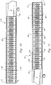
- the ruler strips 20 provide a preferred embodiment of a ruler adjacent the window shade 10 to assist in resizing of the window shade 10 to properly fit within the window frame F.
- a retainer can be utilized to hold the window shade during the cutting procedure ( Figures 7-9 ) when the window shade 10 is resized.
- Reference numeral 110 is directed to an arched window shade assembly ( Figure 12 ) with a rule 140 ( Figure 13 ) which provides a variation on the ruler of this invention for properly resizing an arched window shade 120 to fit within an arched window frame above a sill S of an arched window.
- the window shade 10 can be any of a variety of different window shades of generally rectangular form ( Figures 1-3 ) or arched form ( Figure 12 ).
- at least one ruler strip 20 is provided adjacent an edge of the window shade 10.
- the ruler strip 20 can be attached to the window shade 10 or merely located adjacent the window shade 10 during measurement and cutting procedures associated with resizing the window shade 10 according to this invention.
- Graduations 28 and indicia 29 are located upon the ruler strip 20 ( Figures 10 and 11 ) that do not accurately represent a width of the window shade 10, but rather represent a location on the window shade 10 where the window shade 10 should be cut when the window frame F ( Figures 1-3 ) has a width matching the indicia 29.
- the indicia 29 are thus misdescriptive of the width of the window shade 10 and descriptive of the width of the window frame F.
- a retainer 30 is optionally provided which functions both to hold the window shade 10 in a collapsed form during cutting of the window shade 10 and also as a cutting guide to guide a cutting tool, such as a knife K ( Figures 7-9 ), during this cutting process.
- a cap 40 in a retainer 30 allows a viewer to see through the cap 40 to view the indicia 29 and graduations 28 of the ruler strip 20 beneath the cap 40.
- a guide slot 50 in the retainer 30 extends vertically into the retainer 30 and assists in guidance of the knife K, or other cutting tool ( Figures 7-9 ).
- the window shade 10 can have any of a variety of different forms of generally rectangular shades or blinds configured to at least partially occlude the passage of light therethrough, particularly when the window shade 10 is located within a window frame F adjacent glass G of a window.
- window shades, window blinds and any other analogous window coverings are together generically referred to by the term "window shades.”
- the window shade 10 includes a top 2 parallel to a bottom 4.
- the bottom 4 typically extends a variable distance away from the top 2, such that the shade 10 is adjustable in height, but typically remains substantially parallel to the top 2.
- a left edge 6 and right edge 8 extend from the top 2 to the bottom 4.
- the edges 6, 8 are typically parallel to each other and spaced from each other by a width of the window shade 10.
- the width of the window shade 10 between the left edge 6 and right edge 8 is typically provided at a standard measurement at least as great as a largest width window frame F in which the window shade 10 is to be deployed.
- window shade 10 must in nearly all cases be custom cut to properly fit within the window frame F. It is desirable that the window shade 10 be similar to but actually slightly less than a width of the window frame F, to provide clearance along the left edge 6 and right edge 8 for proper deployment, height adjustment and symmetric positioning of the window shade 10.
- window shades 10 include cords extending vertically therethrough. Some window shades 10 include visual markings thereon which are centered relative to a vertically extending center line of the window shade 10. In such instances, to maintain a symmetrical character of the window shade 10, it is necessary during resizing of the window shade 10 for equal amounts to be cut from both the left edge 6 and the right edge 8.
- a window shade 10 does not include multiple symmetrically oriented vertically extending cords or other symmetrical patterns, or where an asymmetrical appearance is desired, it is acceptable to cut only the left edge 6 or the right edge 8 of the window shade 10.
- a rule such as the rule 140, described in detail below with respect to the arched window variation of this invention, can be utilized on a rectangular window shade 10, as discussed in detail below.
- the window shade 10 shown in FIGS. 1-11 is described in detail in U.S. patent application Ser. No. 10/194,193 .
- This window shade 10 as well as others often include significantly different internal structures including flexible and rigid portions, optionally cords, optionally pleats, optionally slats and other features.
- the measurement and sizing invention described herein is equally applicable to all such window shades, and is not merely limited to use with the window shade 10 described in detail herein and in the application.
- the ruler strips 20 provide a preferred form of rule or ruler for accurately determining where the shade 10 should be cut.
- the ruler strips 20 of this invention are preferably provided in a set of two including a left ruler strip 20 and a right ruler strip 20 which are mirror images of each other ( FIGS. 10 and 11 ). Hence, each graduation 28 on the left ruler strip 20 has a corresponding graduation 28 on the right ruler strip 20.
- the pair of ruler strips 20 can be identical and not mirror images of each other, in which case when viewing the left edge 6 and right edge 8 of the window shade 10 with the ruler strip 20 adjacent thereto, one of the ruler strips 20 would appear right side up and the other ruler strip would appear upside down. Also, it is conceivable that a single ruler strip could be provided which would extend from the left edge 6 to the right edge 8. Middle portions of such a single ruler would be left blank or could include graduations 28 and indicia 29.
- the ruler strips 20 can be attached, engraved, embossed, printed or otherwise formed into the window shade 10, such as to the top 2 of the window shade 10, in a permanent or removable fashion, or the ruler strips 20 can be provided upon a separate rigid or flexible structure which is merely placed adjacent the window shade 10 during measurement and cutting, but is never actually attached to the window shade 10.
- the ruler strips 20 are attached to the top 2 of the window shade 10, and optionally to also the bottom 4 of the window shade 10. In this way, any error associated with improperly locating the ruler strips 20 adjacent the left edge 6 and right edge 8 can be avoided.
- the ruler strips 20 could be on a separate rigid or flexible structure, such as a yardstick type device or a measuring tape type device for placement next to the window shade 10.
- Each ruler strip 20 includes an outer edge 22 preferably to be placed adjacent the left edge 6 or right edge 8 of the window shade 10.
- An inner edge 24 opposite the outer edge 22 is closer to a middle of the window shade 10.
- Each ruler strip 20 includes an underside 25 ( Figure 4 ) which is preferably formed of a waxy material or is otherwise coated so that it can loosely adhere to an adhesive 26 upon either the underside 25 or the top 2 of the window shade 10.
- the ruler strip 20 can be lifted easily off of the top 2 with the underside 25 releasing the adhesive 26 and leaving the adhesive 26 upon the top 2 of the window shade 10.
- the ruler strip 20 is removed from the top 2 of the window shade 10 after use to resize the shade 10 and the adhesive 26 is exposed for use in attaching the top 2 of the window shade 10 to an upper portion of the window frame F for deployment of the window shade 10 ( Figures 2 and 3 ).
- the adhesive 26 can be placed on an upper surface of the ruler strips 20 with a clear backing strip placed over the adhesive 26 or restricted to only portions of the upper surface, such as down a middle region of the ruler strips 20 so that the graduations 28 and indicia 29 can still be viewed when located alongside the middle region.
- the ruler strips 20 present graduations 28 and indicia 29 on an upper side of the ruler strips 20. These graduations 28 and indicia 29 are visually perceptible markings to assist a user in properly cutting the window shade 10 while it is adjacent to the ruler strips 20.
- each of the graduations 28 is preferably a linear line extending perpendicular to a long axis of the window shade 10.
- multiple graduations 28 are provided upon the ruler strip 20 with each graduation 28 spaced a similar distance away from adjacent graduations.
- the graduations 28 need not extend entirely across the ruler strips 20, but need only extend sufficiently long to clearly identify the line upon which the window shade 10 might potentially be cut. It is also conceivable that the graduations 28 could be in the form of mere dots or points along the ruler strip 20 and still function according to this invention.
- the graduations 28 could also be other visually perceptible markings, such as merely a transition between regions of different color or shading, or other markings appropriate to identify points at which the window shade 10 could be cut.
- the indicia 29 are arranged so that each indicium 29 is associated with a graduation 28. It is not strictly necessary that every graduation 28 include an indicium 29. Rather, only at least some of the graduations 28 need include indicia 29.
- the indicia 29 are representative of measurements, preferably in the form of numbers representative of lengths, such as inches or centimeters.
- the indicia 29 can additionally include lettering (i.e. "in.” or "cm") to represent what type of measurement is represented by the indicia 29.
- the indicia 29 are misdescriptive of the position of the graduations 28 in at least two respects.
- the indicia 29 are adjacent graduations which are twice as close to each other as the graduations would typically be on a standard ruler.
- the indicia "25” would be adjacent a graduation 28 which is only one half inch (on a ruler strip 20 provided in inches) away from a graduation having the indicia "24" adjacent thereto.
- This misdescriptiveness of the indicia 29 simplifies the use of the ruler strips 20 in that the indicia 29 do not represent width of the window shade 10, but rather represent a width of the window frame F into which the window shade 10 will properly fit when cut at the graduation adjacent the indicia selected.
- the graduations 28 are twice as close as they would otherwise be to appropriately compensate.
- a user need not calculate where the window shade 10 must be cut, but merely need measure the window frame F and then cut the window shade 10 at the graduation adjacent the indicia which corresponds with the width of the window frame F.
- the ruler strips 20 are located so that the graduations 28 have indicia 29 adjacent thereto which are similar to but do not exactly represent a distance to the corresponding graduation on the other ruler strip 20 at the other edge of the window shade 10.
- the indicia "30" on the left ruler strip 20 adjacent the left edge 6 might be 29.5 inches away from an indicia " 3 0 " on the right ruler strip 20 adjacent the right edge 8 of the window shade 10.
- This half inch (for example) discrepancy provides a half inch of clearance (one quarter inch at each edge 6, 8) between edges 6, 8 of the window shade 10 and the vertical sides of the window frame F.
- the graduations 28 and indicia 29 are not descriptive of the width of the window shade 10, but rather descriptive of the width of the window frame F into which the window shade 10 can properly fit with desired clearance when cut at the graduation adjacent the indicia representative of the width of the window frame F.
- the retainer 30 is optionally provided first to hold the window shade in its collapsed form during shipping and storage of the window shade 10, and later to assist in the proper positioning of a cutting tool such as a knife K ( Figures 7-9 ) in cutting the window shade 10 where desired.
- the retainer 30 essentially acts as a collar with a central gap sized just large enough to allow the collapsed window. shade 10 to fit within the central gap.
- the retainer 30 includes a floor 32 which is preferably substantially planar with a pair of side walls 34 extending perpendicularly up from edges of the floor 32.
- a cap 40 joins upper edges of the side walls 34 together.
- the cap 40 preferably includes upper facets 42 which extend horizontally toward each other. Angled facets 44 extend down from edges of the upper facets 42 down to a lower facet 46 which extends horizontally to join the angled facets 44 together.
- the lower facet 46 is parallel with the upper facets 42 but lower than the upper facets 42.
- This configuration of the cap 40 is preferred, but is only one form of cap 40 for use in surrounding the central gap of the retainer 30. It is also conceivable that the retainer 30 could be in the form of a vice having a cross-section similar to a letter "C.”
- a guide slot 50 preferably extends through the cap 40 and partially through the side walls 34.
- the guide slot 50 preferably extends in a vertical plane perpendicular to a long axis of the window shade 10 when the window shade is passing through the central gap of the retainer 30.
- the retainer 30 is preferably formed of a material which is rigid but exhibits similar cutability characteristics to the materials from which the window shade 10 is formed. In this way, a cutting tool such as a knife K can initially cut the window shade 10 while the knife K or other cutting tool is located within the guide slot 50. When a bottom of the guide slot 50 has been reached, the cutting tool can continue to cut both the window shade 10 and the retainer 30, in effect deepening the slot.
- the cap 40 is formed in at least some locations with at least partially transparent material so that the indicia 29 and graduations 28 can be viewed through the cap 40.
- openings can be provided within the cap 40 at positions required so that the indicia 29 can be viewed.
- the guide slot 50 can have wide spots therein having a size at least as large as the indicia 29 and spaced from the side walls 34 of the retainer 30 similar to a spacing that the indicia 29 exhibit away from the sides of the window shade 10. These openings in the guide slot 50 would allow the indicia 29 to be viewed therethrough when the retainer 30 is positioned (along arrow A of Figure 4 ) at the position desired. When the proper indicia 29 shows through this opening in the guide slot 50, the graduation 28 would be aligned with the guide slot 50 for the cutting procedure ( Figures 7-9 ).
- the window shade 10 is measured and resized in the following manner utilizing the ruler strips 20, and retainer 30 according to a preferred embodiment of this invention.
- the window shade 10 is provided with the top 2 including left and right ruler strips 20 thereon adjacent the left edge 6 and right edge 8 of the window shade 10.
- the ruler strips 20 are preferably attached to the top 2 of the window shade 10 in a removable fashion with an adhesive 26 beneath the ruler strips 20.
- a user U next measures a width of the window frame F ( Figure 1 ).
- a stretched ruler R i.e. a yardstick
- the window frame F has a non-rectangular or other variable form, it may be desirable to take multiple measurements of the width of the window frame F with the narrowest width of the window frame F being identified. This width for the window frame F is remembered or noted by the user U for use throughout the process of cutting the window shade 10 according to this invention.
- the user U slides the retainer 30 (along arrow A of Figure 4 ) until the graduation 28 is adjacent the guide slot 50 of the retainer 30 which has the indicium 29 adjacent thereto which matches the width of the window frame F.
- the user U utilizes a knife K or other cutting tool ( Figures 7-9 ) to cut the window shade 10 at the graduation 28 or at a location between graduations that correspond with a measurement of the window frame F.
- the knife K is placed within the guide slot 50 and is used to cut down through the window shade 10.
- the knife K continues to cut both the window shade 10 and the remainder of the retainer 30 until the knife K or other cutting tool has reached the floor 32 of the retainer 30.
- the user U then repeats this procedure with a second retainer 30 at the right edge 8 of the window shade 10.
- the same indicium 29 is utilized in cutting the right edge 8 of the window shade 10 as is utilized in cutting the left edge 6 of the window shade 10.
- the ruler strips 20 can be pealed away from the top 2 of the window shade 10 so that the adhesive 26 is available for holding the top 2 of the window shade 10 adjacent the window frame F in front of the window G.
- the window shade 10 will have a width which is slightly less than a width of the window frame F with an appropriate amount of clearance adjacent sides of the window shade 10 and with the window shade 10 exhibiting a symmetrical appearance, having had a similar amount cut from either edge of the window shade 10.
- the retainer 30 it is not strictly required that the retainer 30 be utilized. Rather, the user U can merely identify the graduation 28 having the indicium 29 adjacent thereto which matches the width of the window frame F and then utilize a cutting tool, such as a knife K or any other form of cutting tool, to cut the window shade 10 adjacent the graduation 28.
- a cutting tool such as a knife K or any other form of cutting tool
- the following formulas can be utilized in calculating the proper location of the graduations 28 and indicia 29 relative to the outer edge 22 and inner edge 24 of the ruler strips 20 and relative to each other at the left and right edges 6, 8 of the window shade 10.
- an arched window shade assembly 110 including an arched shade 120 and a retainer 150 can be utilized.
- Such an assembly 110 is particularly described in U.S. patent application Ser. No. 10/318,975 .
- an arched window shade assembly 110 starts with a generally rectangular form but then is expanded in a fanned fashion so that a second end 122 is colinear with the first end 124, in the case of a half circle arched shade 120 (other degrees of angular displacement are possible).
- An inside edge 126 and outside edge 128 maintain a constant distance from each other, but the inside edge 126 is essentially maintained near a central point with the outside edge 128 extending along a perimeter of the arched shade 120.
- a retainer 150 is provided to hold the arched shade 120 in this fanned form adjacent the arched window, with the retainer 150 resting upon a sill S beneath a curved ceiling C forming the window frame adjacent the arched window.
- the retainer 150 can include a base 152 to help support the inside edge 126.
- the inside edge 126 does not precisely reside at a single point, but rather exhibits a small arch with a small space adjacent thereto. Also, it is desirable with an arched window shade 120 that some clearance be provided adjacent the curved ceiling C. For this reason, a measuring and cutting system akin to that of the preferred embodiment of this invention is utilized which is in fact misdescriptive of a width of the arched shade 120, but rather is descriptive of a height of the arched window adjacent to which the arched shade 120 is to be placed.
- the rule 140 includes a series of graduations 142 (i.e. lines or other generally linear markings) extending along at least a portion of the thickness of the shade 120, preferably adjacent both the first end 124 and second end 122.
- Indicia 144 preferably in the form of numbers, are provided adjacent at least some of the graduations 142 to identify the graduations 142.
- a rule 140 is provided on both the first end 124 and the second end 122.
- rule 140 can be identical on both the first end 124 and second end 122, preferably English units of measurement are provided on the rule 140 on the first end 124 and metric units of measurement are provided on the rule 140 on a second end 122. Such a dual system could similarly be used with the preferred embodiment of this invention.
- the graduations 141 and indicia 144 of the rule 140 are distorted slightly from a true measurement of a width of the shade 120 from the inside edge 126 to the outside edge 128. Specifically, the rule 140 is shifted a slight amount toward the inside edge 126. This slight amount matches a radius of the hump 160 within the retainer 150, described in detail below. Because the hump 160 causes the inside edge 126 of the shade 120 to be slightly raised above the sill S, the user avoids the complexity of subtracting out the height of the hump 160 when properly measuring and cutting the shade 120.
- the rule 140 is provided with the graduations 142 and corresponding indicia 144 shifted one half inch toward the inside edge 126.
- the number "120" would be an indicia 144 adjacent a graduation 142 which would in actuality be 19.5 inches away from the inside edge 126 of the shade 120.
- the shade 120 will have been cut to have a width between the inside edge 126 and the outside edge 128 which is 19.5 inches.
- the hump 160 When the shade 120 is later deployed adjacent the retainer 150, the hump 160 will raise the shade 120 by a half inch so that the shade will actually have a height of 20 inches above the sill.
- the rule 140 is also shifted additionally slightly (i.e. one fourth of an inch) to accommodate thickness of the base 152 of the retainer 150 and to provide a margin of clearance for the shade 120.
- a user merely measures a height of the window and then cuts the shade 120 at the indicia 144 which matches the measurement made of the window height.
- either a portion or all of the rule 140 is provided upon a backing strip 148 which protects an adhesive 146 on the first end 124 and second end 122.
- the backing strip 148 can be removed to expose adhesive 146 underneath for securing the ends 122, 124 to a base 152 of the retainer 150 and to the sill S. In this way, the shade 120 is securely held to the retainer 150 and to the sill S when deployed.
- Other fasteners could similarly be utilized including tacks or other mechanical fasteners or a user could provide a separate adhesive, such as glue or paste, or utilize adhesive tape, or any other fastening means.
- the rule 140 can be used on a rectangular window shade 120 ( Figures 1-3 ) in situations where maintenance of a symmetrical nature of the shade 120 is not required or not affected by removal of material from only one edge of the shade 120.
- This invention exhibits industrial applicability in that it provides a window shade measuring and cutting system which simplifies the process of measuring and cutting a window shade to fit within a window frame adjacent a rectangular or arched window.
- Another object of the present invention is to provide a system for simplifying the measurement of a window shade prior to cutting the window shade to properly fit within a window frame.
- Another object of the present invention is to provide a window shade measurement system which allows equal amounts to be removed from both left and right edges of a window shade without requiring excessive measurements or calculations to be made.
- Another object of the present invention is to provide a window shade sizing system which includes a retainer to both hold the window shade and guide a cutting tool where needed to cut excess portions of the window shade away.
- Another object of the present invention is to provide a window shade with measurement guide that automatically accounts for a desired amount of clearance from surrounding edges of a window shade during resizing of a window shade to fit within a window frame.
Landscapes
- Engineering & Computer Science (AREA)
- Structural Engineering (AREA)
- Architecture (AREA)
- Civil Engineering (AREA)
- Length-Measuring Instruments Using Mechanical Means (AREA)
- Details Of Cutting Devices (AREA)
Claims (13)
- Procédé de dimensionnement d'une largeur de store (10) de fenêtre entre des bords de celui-ci, de sorte à permettre au store de fenêtre de rentrer dans un cadre de fenêtre entourant une fenêtre, les étapes comprenant :le positionnement d'une pluralité de graduations visibles (28) sur une bande flexible de matière (20), et la fixation de la bande flexible de matière sur au moins une surface allongée du store (10) de fenêtre, chaque graduation étant éloignée à une distance différente des bords d'un store de fenêtre à découper lorsque les graduations sont placées de manière adjacente au store de fenêtre ;une pluralité d'indices visibles (29) étant fournie, chaque indice (29) étant placé de manière adjacente à l'une des graduations, et chaque indice (29) étant faussement descriptif d'une largeur que le store (10) de fenêtre présenterait si le store de fenêtre était découpé au niveau de la graduation (28) adjacente audit indice, par lesquels au moins une des graduations est éloignée des bords du store de fenêtre à une distance différente d'une distance représentée par l'indice adjacent à l'au moins une graduation, et dans lequel une grandeur de la fausse description comprend une grandeur d'espace libre entre les bords du store et les côtés d'un cadre (F) adjacent à la fenêtre (G),la mesure d'une largeur du cadre (F) de fenêtre ;l'identification d'au moins un indice correspondant à la largeur du cadre de fenêtre à partir de ladite étape de mesure ; etla découpe du store de fenêtre à proximité d'au moins une graduation adjacente à l'indice indiqué dans ladite étape d'identification.
- Procédé selon la revendication 1 comprenant l'étape supplémentaire de découpe de chaque bord du store (10) de fenêtre au niveau d'une graduation (28) adjacente à un indice similaire (29) représentatif d'une largeur du cadre (F) de fenêtre.
- Procédé selon la revendication 2 dans lequel ladite étape de découpe comprend l'étape de découpe d'une grandeur similaire à la fois depuis un bord gauche (6) et un bord droit (8) du store (10) de fenêtre.
- Procédé selon l'une des revendications précédentes, comprenant l'étape supplémentaire de configuration de la bande flexible de matière (20) afin qu'elle comprenne un moyen d'être fixée de manière amovible sur le store (10) de fenêtre.
- Procédé selon la revendication 4 comprenant l'étape supplémentaire de fourniture d'un adhésif entre la bande flexible de matière (20) et le store (10), la bande flexible de matière et l'adhésif étant sélectionnés parmi des matières qui permettent à l'adhésif de rester fixé sur le store lorsque la bande flexible de matière est retirée du store, l'adhésif ayant une résistance suffisante pour supporter un poids du store suspendu en-dessous d'une surface horizontale à travers l'adhésif.
- Procédé selon la revendication 5 comprenant l'étape supplémentaire de fixation de la bande flexible de matière (20) sur au moins une extrémité d'un store (10) de fenêtre cintré, les graduations (28) sur la bande flexible de matière comportant un indice (29) adjacent à celle-ci, qui est représentatif d'une combinaison d'une largeur du store de fenêtre cintré avant expansion dans une configuration en éventail lorsqu'il est découpé au niveau de la graduation adjacente à l'indice, et d'une grandeur d'espace libre adjacente à un bord extérieur du store de fenêtre cintré et d'une grandeur d'espace libre adjacente à un bord intérieur du store de fenêtre cintré.
- Procédé selon la revendication 5 comprenant l'étape supplémentaire de fixation de la bande flexible de matière (20) sur un store (10) de fenêtre rectangulaire, les graduations (28) sur la bande flexible de matière comportant un indice (29) adjacent à celle-ci, qui est représentatif d'une combinaison d'une largeur du store lorsqu'il est découpé au niveau de la graduation adjacente à l'indice, et d'une grandeur d'espace libre adjacente aux bords gauche et droit (6, 8) du store de fenêtre lorsque le store de fenêtre est découpé au niveau de la graduation adjacente à l'indice.
- Procédé selon l'une des revendications précédentes comprenant les étapes supplémentaires de placement d'un dispositif (30) de retenue adjacent au store (10) de fenêtre, et de découpe du store de fenêtre à travers le dispositif de retenue.
- Procédé selon la revendication 8 comprenant l'étape supplémentaire de fourniture d'une fente (50) à l'intérieur du dispositif de retenue, et de guidage d'un outil (K) de découpe à l'intérieur de la fente du dispositif de retenue pendant lesdites étapes de découpe.
- Store de fenêtre avec un système de mesure permettant de mesurer le store (10) de fenêtre avant de le découper, comprenant de manière combinée :un store de fenêtre comportant un bord gauche et un bord droit ;une règle (20) comprenant au moins une graduation (28) sur celle-ci ,ladite règle comprenant au moins un indice (29) sur celle-ci, ledit au moins un indice étant adjacent à ladite une graduation ; etledit indice étant faussement descriptif d'une largeur dudit store après que ledit store est découpé au niveau de ladite au moins une graduation adjacente audit un indice,caractérisé en ce quela règle (20) est fixée sur le store (10), et en ce qu'une différence entre une mesure représentée par ledit indice (29) et une largeur du store (10) après que le store est découpé au niveau de ladite au moins une graduation (28) adjacente audit au moins un indice comprend une grandeur d'espace libre grâce à laquelle le store est adapté pour rentrer dans un cadre (F) de fenêtre adjacent à une fenêtre (G) avec un espace libre situé entre le cadre de fenêtre et lesdits bords du store de fenêtre.
- Store de fenêtre selon la revendication 10 dans lequel ladite règle (20) est positionnée par rapport au store (10) de fenêtre avec ladite au moins une graduation (28) éloignée de l'un des bords du store de fenêtre à une distance inférieure à une distance indiquée par ledit au moins un indice (29) adjacent à ladite au moins une graduation.
- Store de fenêtre selon la revendication 10 ou 11, dans lequel le store (10) de fenêtre est sensiblement rectangulaire avec une partie supérieure (2) et inférieure (4) s'étendant entre ledit bord gauche (6) et ledit bord droit (8), ledit bord gauche et ledit bord droit étant orientés parallèlement l'un à l'autre.
- Store de fenêtre selon la revendication 10 ou 11, dans lequel le store (10) de fenêtre est cintré, ledit bord gauche (6) conservant une distance constante par rapport audit bord droit (8), et l'un desdits bords présentant une forme incurvée et l'autre desdits bords étant adjacent à un point central autour duquel le store de fenêtre est cintré.
Applications Claiming Priority (2)
| Application Number | Priority Date | Filing Date | Title |
|---|---|---|---|
| US10/402,452 US6865817B2 (en) | 2003-03-27 | 2003-03-27 | Window shade with measurement guide |
| PCT/US2004/008781 WO2004088084A1 (fr) | 2003-03-27 | 2004-03-22 | Store a enroulement automatique a guide de mesure |
Publications (2)
| Publication Number | Publication Date |
|---|---|
| EP1623085A1 EP1623085A1 (fr) | 2006-02-08 |
| EP1623085B1 true EP1623085B1 (fr) | 2012-05-02 |
Family
ID=32989700
Family Applications (1)
| Application Number | Title | Priority Date | Filing Date |
|---|---|---|---|
| EP20040758193 Expired - Lifetime EP1623085B1 (fr) | 2003-03-27 | 2004-03-22 | Store a enroulement automatique a guide de mesure |
Country Status (5)
| Country | Link |
|---|---|
| US (1) | US6865817B2 (fr) |
| EP (1) | EP1623085B1 (fr) |
| AT (1) | ATE556193T1 (fr) |
| CA (1) | CA2520646A1 (fr) |
| WO (1) | WO2004088084A1 (fr) |
Families Citing this family (33)
| Publication number | Priority date | Publication date | Assignee | Title |
|---|---|---|---|---|
| US6604443B2 (en) * | 2001-07-23 | 2003-08-12 | Newell Window Furnishings, Inc. | Blind and shade cutting center |
| US20050126344A1 (en) * | 2003-12-15 | 2005-06-16 | Jones Joseph P. | Bottle opener with display surface |
| US20050188515A1 (en) * | 2004-02-26 | 2005-09-01 | Springs Window Fashions Lp | Louver retainer and method of use |
| US7194811B2 (en) * | 2004-03-22 | 2007-03-27 | Shades Unlimited, Inc. | Cutting guide for a window shade |
| US7549615B2 (en) * | 2004-10-15 | 2009-06-23 | Shades Unlimited, Inc. | Compression mount for window coverings |
| US7249623B2 (en) * | 2004-10-29 | 2007-07-31 | Chhun Justin S | Bracing bracket for arched window blinds |
| US7293368B1 (en) * | 2005-10-03 | 2007-11-13 | Frank Faulk | Measurement system and method |
| CN2832462Y (zh) * | 2005-10-26 | 2006-11-01 | 郑立铭 | 窗帘切割辅助器 |
| US7254899B2 (en) * | 2005-11-17 | 2007-08-14 | Shade-O-Matic Ltd. | Arch measuring device |
| DE102006006791B4 (de) * | 2006-02-14 | 2011-12-29 | Motiondrive Ag | Verfahren, System und Maßstab zur Bestimmung und/oder Simulation von Größenverhältnissen |
| US20070246171A1 (en) * | 2006-04-24 | 2007-10-25 | Li-Ming Cheng | Window shade cutting aid |
| US20080135190A1 (en) * | 2006-12-11 | 2008-06-12 | Li-Ming Cheng | Window covering cutting aid |
| US9427813B2 (en) * | 2007-07-31 | 2016-08-30 | Newell Window Furnishing, Inc. | Window covering sizing method and apparatus |
| US8322260B2 (en) | 2007-07-31 | 2012-12-04 | Newell Window Furnishings, Inc. | Window covering sizing method and apparatus |
| US8839701B2 (en) | 2007-07-31 | 2014-09-23 | Newell Window Furnishings, Inc. | Window covering sizing method and apparatus |
| US8256333B2 (en) | 2007-07-31 | 2012-09-04 | Newell Window Furnishings, Inc. | Window covering sizing method and apparatus |
| US7987754B2 (en) | 2007-07-31 | 2011-08-02 | Newell Window Furnishings, Inc. | Window covering sizing method and apparatus |
| US8065861B2 (en) * | 2008-01-07 | 2011-11-29 | Newell Window Furnishings, Inc. | Blind packaging |
| US20100199824A1 (en) * | 2008-09-12 | 2010-08-12 | Remmert Joseph M | Cutdown machine for coverings to fit architectural openings |
| CN102116130B (zh) * | 2010-01-04 | 2015-06-24 | 汤军 | 一种用户自行组装式回卷纱窗 |
| US8479925B2 (en) | 2010-07-19 | 2013-07-09 | Newell Window Furnishings, Inc. | Display system |
| US9266639B2 (en) | 2010-07-19 | 2016-02-23 | Newell Window Furnishings, Inc. | Blind packaging and methods of cutting window coverings |
| USD899895S1 (en) | 2018-02-23 | 2020-10-27 | House of Atlas, LLC | Surface mount |
| US11215217B2 (en) | 2018-02-23 | 2022-01-04 | House of Atlas, LLC | Surface mount |
| US10959559B2 (en) | 2019-03-08 | 2021-03-30 | House of Atlas, LLC | Dual-mounted end cap system and locking system for an adjustable rod |
| US11889958B2 (en) | 2019-04-17 | 2024-02-06 | House of Atlas, LLC | Rotating shower rod |
| US11382447B2 (en) | 2019-07-30 | 2022-07-12 | House of Atlas, LLC | Adjustable rod features |
| US12031565B2 (en) | 2020-01-10 | 2024-07-09 | Olson Ip Technologies, Inc. | Suction mount and brackets and accessories therefor |
| USD1005084S1 (en) | 2020-01-21 | 2023-11-21 | Olson Ip Technologies, Inc. | Suction cup mount |
| US11825940B2 (en) | 2020-05-18 | 2023-11-28 | House of Atlas, LLC | Customizable shower caddy |
| US11974704B2 (en) | 2022-03-03 | 2024-05-07 | House Of Atlas Llc | Customizable shower caddy |
| CN120418520A (zh) * | 2022-12-01 | 2025-08-01 | 英特宜家系统有限公司 | 用于调整窗覆盖布置结构的尺寸的装置 |
| US12303053B1 (en) | 2023-11-14 | 2025-05-20 | House of Atlas, LLC | Spring-biased end caps for rod assembly and methods of use |
Family Cites Families (74)
| Publication number | Priority date | Publication date | Assignee | Title |
|---|---|---|---|---|
| US2134332A (en) * | 1937-02-04 | 1938-10-25 | Freda C Hubbard | Curtain roll cutter |
| US2187087A (en) * | 1937-12-31 | 1940-01-16 | Earl R Leary | Flexible template |
| US2932897A (en) * | 1958-06-26 | 1960-04-19 | Topflight Corp | Measuring device |
| US3760664A (en) | 1971-10-06 | 1973-09-25 | Clopay Corp | Window shade cutter |
| US3936944A (en) * | 1972-04-07 | 1976-02-10 | Zachary Paul Byne | Linear cut sewing tape |
| US3782235A (en) * | 1972-12-29 | 1974-01-01 | M Curcio | Miter box |
| US4539239A (en) | 1977-01-11 | 1985-09-03 | Newell Companies, Inc. | Window shade, and method apparatus for manufacturing same |
| US4102385A (en) | 1977-05-23 | 1978-07-25 | Clopay Corporation | Window shade |
| US4139941A (en) * | 1977-09-22 | 1979-02-20 | Clopay Corporation | Window shade cutter |
| US4271893A (en) | 1979-03-26 | 1981-06-09 | Mccluskey William A | Window blind cord control apparatus |
| US4403415A (en) | 1981-05-14 | 1983-09-13 | Fox Valley Corporation (Breneman Div.) | Window shade roller with shade cutting assembly |
| US4597430A (en) | 1984-02-03 | 1986-07-01 | Marquez Fidencio G | Window shade sealing system |
| US4539238A (en) | 1984-06-14 | 1985-09-03 | Markowitz Steven L | Tear-away window shade |
| US4589313A (en) | 1985-05-30 | 1986-05-20 | Joanna Western Mills Company | Automatic shade cutter |
| US4711005A (en) | 1985-09-12 | 1987-12-08 | Joanna Western Mills Company | Method and apparatus for making slats for window blinds and the like from a continuous web of plastic material |
| US4712457A (en) | 1986-06-20 | 1987-12-15 | Kenney Manufacturing Company | Apparatus and method for cutting window shades |
| US4819530A (en) | 1986-10-24 | 1989-04-11 | Teh Yor Industrial Co., Ltd. | Apparatus and method for trimming a venetian blind assembly |
| US4776096A (en) | 1986-12-29 | 1988-10-11 | Chang A Shien | Scissors means particularly for cutting blind's slats |
| US4836265A (en) | 1987-04-13 | 1989-06-06 | Bussert Althea J | Temporary window shades |
| US4758042A (en) | 1987-09-02 | 1988-07-19 | Liu Chi Nan | Collapsible sun shade |
| US4907325A (en) | 1988-08-09 | 1990-03-13 | Hsu Pei H | Blind trimmer |
| US5072494A (en) | 1988-08-19 | 1991-12-17 | Newell Operating Company | Method and apparatus of infinitely sizing a mini blind |
| US4993131C1 (en) | 1988-08-19 | 2001-04-24 | Newell Window Furnishings Inc | Method and apparatus of infinitely sizing a mini blind |
| US5056388A (en) | 1990-01-22 | 1991-10-15 | Hunter Douglas International N.V. | Blind cutting machine |
| US5010939A (en) * | 1990-02-16 | 1991-04-30 | King William J | Blind for arched windows |
| US5025848A (en) | 1990-04-20 | 1991-06-25 | Prochaska Maria J | Temporary window shade |
| US5158127A (en) | 1991-03-11 | 1992-10-27 | Schumacher Donald W | Temporary covering for a window or the like |
| US6003217A (en) | 1991-07-08 | 1999-12-21 | Newell Operating Company | Size-in-store pleated shade and method and apparatus of sizing |
| US5279473A (en) | 1992-05-01 | 1994-01-18 | 2844788 Canada Ltee | Cord retraction device |
| US5354011A (en) | 1993-02-26 | 1994-10-11 | 2844788 Canada Ltee | Take-up reel for window blind cords |
| US5456149A (en) | 1993-02-18 | 1995-10-10 | Newell Operating Co. | Sizing system for window coverings |
| US5339716A (en) | 1993-02-22 | 1994-08-23 | Newell Operating Co. | Mini blind cutter |
| US6330899B1 (en) | 1994-04-06 | 2001-12-18 | Newell Window Furnishings. Inc. | Cordless balanced window covering |
| AU712085B2 (en) | 1995-05-19 | 1999-10-28 | Hunter Douglas International N.V. | Method and apparatus for producing a plurality of sequentially arranged edge contoured slats |
| US5813306A (en) * | 1995-06-01 | 1998-09-29 | Great Neck Saw Manufacturers, Inc. | Mitre box or similar article |
| US6178857B1 (en) | 1995-09-11 | 2001-01-30 | Shade-O-Matic Limited | Method of end trimming of blinds |
| DE29518057U1 (de) | 1995-11-15 | 1995-12-21 | Prosch, Dieter, 22083 Hamburg | Vorhang |
| US5816126A (en) | 1996-02-02 | 1998-10-06 | Holis Metal Industries, Ltd. Israeli Co. | Cutter for shortening blinds |
| US6149094A (en) | 1996-03-20 | 2000-11-21 | Barnes Group Inc. | Spring motor |
| US5897730A (en) | 1996-07-16 | 1999-04-27 | Teh Yor Industrial Co., Ltd. | Method for producing shade material |
| US5799557A (en) | 1997-03-19 | 1998-09-01 | Wang; Cherng-Fa | Venetian blind cutting machine |
| US6167789B1 (en) | 1997-07-25 | 2001-01-02 | Newell Operating Company | Dual mini-blind cutter |
| US6171424B1 (en) | 1997-10-09 | 2001-01-09 | Comfortex Window Fashions | Method of making fabric venetian blinds |
| CA2308952C (fr) | 1997-11-04 | 2004-11-09 | Andrew J. Toti | Systeme d'entrainement a ressort plat et stores de fenetre |
| US6435066B1 (en) | 1997-12-18 | 2002-08-20 | Springs Window Fashions Division, Inc. | Cutting apparatus for window covering and methods therefor |
| US5927172A (en) | 1998-01-21 | 1999-07-27 | Wang; Cherng-Fa | Venetian blind cutting machine |
| CA2230839C (fr) | 1998-02-26 | 2004-01-06 | Stores All-Teck P.T.B. Inc./All-Teck Blinds P.T.B. Inc. | Machine pour couper les mini-stores |
| AUPP301698A0 (en) | 1998-04-15 | 1998-05-07 | Modra, Christopher Max | Wood venetian cut punch and ladder machine |
| US6257301B1 (en) * | 1998-07-31 | 2001-07-10 | International Wood Shutters, Inc. | Modular window blind or shade assembly |
| US6029734A (en) | 1999-01-04 | 2000-02-29 | Industrial Technology Research Institute | Venetian blind provided with slat-lifting mechanism having a concealed pull cord |
| US6098694A (en) | 1999-01-19 | 2000-08-08 | Ohanesian; Harout | User-sizeable headrail assembly |
| US6024154A (en) | 1999-01-28 | 2000-02-15 | Industrial Technology Research Institute | Venetian blind lifting mechanism provided with concealed pull cords |
| US6637124B2 (en) * | 1999-04-20 | 2003-10-28 | 3M Innovative Properties Company | Adhesive measuring tape |
| CA2312533C (fr) | 1999-06-28 | 2003-01-07 | Shade-O-Matic Limited | Dispositif de decoupage de stores verticaux |
| US6240824B1 (en) | 1999-07-14 | 2001-06-05 | Ching Feng /Blinds Ind. Co., Ltd. | Blind cutting machine |
| US7017459B2 (en) | 1999-07-23 | 2006-03-28 | Shade-O-Matic Limited | Blind cut down machine |
| US6089134A (en) | 1999-07-23 | 2000-07-18 | Shade-O-Matic Limited | Multi blind trim machine |
| US6336388B1 (en) | 1999-07-23 | 2002-01-08 | Shade-O-Matic Limited | Rotary saw cutter blind cut down machine |
| TW453243U (en) | 1999-12-16 | 2001-09-01 | Ind Tech Res Inst | Improved sawing and cutting mechanism for venetian blind |
| US6289965B1 (en) | 2000-02-11 | 2001-09-18 | Newell Operating Company | Take-up drum for a cordless shade counterbalance |
| US6571853B1 (en) | 2000-07-06 | 2003-06-03 | Newell Window Furnishings, Inc. | Cordless blind having variable resistance to movement |
| US6725897B2 (en) | 2000-08-22 | 2004-04-27 | Newell Window Furnishings, Inc. | Variable friction device for a cordless blind |
| US6427571B1 (en) | 2000-08-24 | 2002-08-06 | Ching Feng Blinds Ind. Co., Ltd. | Venetian blind cutting machine |
| US6644375B2 (en) | 2001-01-09 | 2003-11-11 | Newell Window Furnishings | Cordless blind brake |
| US6644372B2 (en) | 2001-03-22 | 2003-11-11 | Ren Judkins | Cordless blind |
| US20020148134A1 (en) * | 2001-04-17 | 2002-10-17 | Meyer Paul A. | Methods and apparatus for providing reference measurements |
| US6615698B2 (en) | 2001-05-30 | 2003-09-09 | Custom Craft Co. | Dual-end blinds trimming machine |
| US6604443B2 (en) | 2001-07-23 | 2003-08-12 | Newell Window Furnishings, Inc. | Blind and shade cutting center |
| US20030033919A1 (en) | 2001-08-15 | 2003-02-20 | Industrial Technology Research Institute | Venetian blind cutting machine having a plurality of interchangeable tools of various specifications |
| US6508293B1 (en) | 2001-09-06 | 2003-01-21 | Tai-Long Huang | Spring motor assembly for a venetian blind without outside hanging lifting cords |
| US6877409B2 (en) | 2001-10-12 | 2005-04-12 | Teh Yor Industrial Co., Ltd. | Cutting apparatus and method for venetian blinds |
| US6644373B2 (en) | 2001-11-08 | 2003-11-11 | Newell Window Furnishings, Inc. | Cordless blind |
| US7096917B2 (en) | 2001-12-14 | 2006-08-29 | Newell Window Furnishings, Inc. | One way brake for a cordless blind |
| CA2368359C (fr) | 2002-01-16 | 2006-11-14 | Industrial Technology Research Institute | Mecanisme dissimule de commande de levage de store venitien |
-
2003
- 2003-03-27 US US10/402,452 patent/US6865817B2/en not_active Expired - Lifetime
-
2004
- 2004-03-22 EP EP20040758193 patent/EP1623085B1/fr not_active Expired - Lifetime
- 2004-03-22 AT AT04758193T patent/ATE556193T1/de active
- 2004-03-22 WO PCT/US2004/008781 patent/WO2004088084A1/fr not_active Ceased
- 2004-03-22 CA CA 2520646 patent/CA2520646A1/fr not_active Abandoned
Also Published As
| Publication number | Publication date |
|---|---|
| WO2004088084A1 (fr) | 2004-10-14 |
| ATE556193T1 (de) | 2012-05-15 |
| CA2520646A1 (fr) | 2004-10-14 |
| US20040187325A1 (en) | 2004-09-30 |
| US6865817B2 (en) | 2005-03-15 |
| EP1623085A1 (fr) | 2006-02-08 |
Similar Documents
| Publication | Publication Date | Title |
|---|---|---|
| EP1623085B1 (fr) | Store a enroulement automatique a guide de mesure | |
| US7194811B2 (en) | Cutting guide for a window shade | |
| US3687770A (en) | Picture mat and mount method and article | |
| US4901419A (en) | A-frame window covering mounting arrangement | |
| US5263529A (en) | Decorative decal system for louvered devices | |
| US4660339A (en) | Wall system | |
| US6321457B1 (en) | Cutting template and method of using same | |
| US5950321A (en) | Adhesive tape measurement for lap-siding building construction | |
| GB2189920A (en) | Apparatus and method for automatic layout of sign text | |
| US20040088870A1 (en) | Transparent measuring device with enhanced visibility lines | |
| US20050178013A1 (en) | Transparent measuring device with enhanced visibility lines | |
| US5768795A (en) | Stud template | |
| US6843299B2 (en) | Bracket rail for window coverings | |
| US7000329B2 (en) | Transparent measuring device | |
| US6782633B1 (en) | Flexible guide for identifying a mounting hole | |
| US20060207399A1 (en) | Blind packaging and method of cutting blinds | |
| US11175120B2 (en) | Device for measuring, marking, cutting, and sewing material | |
| US20070261282A1 (en) | Indoor modular panoramic signs | |
| US4049479A (en) | Method of installing decals on vertically ribbed trailer bodies | |
| US20040112548A1 (en) | Shade for an arched window | |
| US4402673A (en) | Display holder | |
| EP2701863B1 (fr) | Production de lettres profilées à l'aide de profils | |
| GB2052124A (en) | Display apparatus | |
| US4936176A (en) | Mat cutter alignment and squaring tool | |
| JP3231853U (ja) | 建材割付用具 |
Legal Events
| Date | Code | Title | Description |
|---|---|---|---|
| PUAI | Public reference made under article 153(3) epc to a published international application that has entered the european phase |
Free format text: ORIGINAL CODE: 0009012 |
|
| 17P | Request for examination filed |
Effective date: 20051026 |
|
| AK | Designated contracting states |
Kind code of ref document: A1 Designated state(s): AT BE BG CH CY CZ DE DK EE ES FI FR GB GR HU IE IT LI LU MC NL PL PT RO SE SI SK TR |
|
| DAX | Request for extension of the european patent (deleted) | ||
| 17Q | First examination report despatched |
Effective date: 20100415 |
|
| GRAP | Despatch of communication of intention to grant a patent |
Free format text: ORIGINAL CODE: EPIDOSNIGR1 |
|
| GRAS | Grant fee paid |
Free format text: ORIGINAL CODE: EPIDOSNIGR3 |
|
| GRAA | (expected) grant |
Free format text: ORIGINAL CODE: 0009210 |
|
| AK | Designated contracting states |
Kind code of ref document: B1 Designated state(s): AT BE BG CH CY CZ DE DK EE ES FI FR GB GR HU IE IT LI LU MC NL PL PT RO SE SI SK TR |
|
| REG | Reference to a national code |
Ref country code: GB Ref legal event code: FG4D |
|
| REG | Reference to a national code |
Ref country code: CH Ref legal event code: EP Ref country code: AT Ref legal event code: REF Ref document number: 556193 Country of ref document: AT Kind code of ref document: T Effective date: 20120515 |
|
| REG | Reference to a national code |
Ref country code: IE Ref legal event code: FG4D |
|
| REG | Reference to a national code |
Ref country code: DE Ref legal event code: R096 Ref document number: 602004037638 Country of ref document: DE Effective date: 20120628 |
|
| REG | Reference to a national code |
Ref country code: NL Ref legal event code: VDEP Effective date: 20120502 |
|
| PG25 | Lapsed in a contracting state [announced via postgrant information from national office to epo] |
Ref country code: CY Free format text: LAPSE BECAUSE OF FAILURE TO SUBMIT A TRANSLATION OF THE DESCRIPTION OR TO PAY THE FEE WITHIN THE PRESCRIBED TIME-LIMIT Effective date: 20120502 Ref country code: SE Free format text: LAPSE BECAUSE OF FAILURE TO SUBMIT A TRANSLATION OF THE DESCRIPTION OR TO PAY THE FEE WITHIN THE PRESCRIBED TIME-LIMIT Effective date: 20120502 Ref country code: PL Free format text: LAPSE BECAUSE OF FAILURE TO SUBMIT A TRANSLATION OF THE DESCRIPTION OR TO PAY THE FEE WITHIN THE PRESCRIBED TIME-LIMIT Effective date: 20120502 Ref country code: FI Free format text: LAPSE BECAUSE OF FAILURE TO SUBMIT A TRANSLATION OF THE DESCRIPTION OR TO PAY THE FEE WITHIN THE PRESCRIBED TIME-LIMIT Effective date: 20120502 |
|
| REG | Reference to a national code |
Ref country code: AT Ref legal event code: MK05 Ref document number: 556193 Country of ref document: AT Kind code of ref document: T Effective date: 20120502 |
|
| PG25 | Lapsed in a contracting state [announced via postgrant information from national office to epo] |
Ref country code: GR Free format text: LAPSE BECAUSE OF FAILURE TO SUBMIT A TRANSLATION OF THE DESCRIPTION OR TO PAY THE FEE WITHIN THE PRESCRIBED TIME-LIMIT Effective date: 20120803 Ref country code: SI Free format text: LAPSE BECAUSE OF FAILURE TO SUBMIT A TRANSLATION OF THE DESCRIPTION OR TO PAY THE FEE WITHIN THE PRESCRIBED TIME-LIMIT Effective date: 20120502 Ref country code: PT Free format text: LAPSE BECAUSE OF FAILURE TO SUBMIT A TRANSLATION OF THE DESCRIPTION OR TO PAY THE FEE WITHIN THE PRESCRIBED TIME-LIMIT Effective date: 20120903 |
|
| PG25 | Lapsed in a contracting state [announced via postgrant information from national office to epo] |
Ref country code: BE Free format text: LAPSE BECAUSE OF FAILURE TO SUBMIT A TRANSLATION OF THE DESCRIPTION OR TO PAY THE FEE WITHIN THE PRESCRIBED TIME-LIMIT Effective date: 20120502 |
|
| PG25 | Lapsed in a contracting state [announced via postgrant information from national office to epo] |
Ref country code: EE Free format text: LAPSE BECAUSE OF FAILURE TO SUBMIT A TRANSLATION OF THE DESCRIPTION OR TO PAY THE FEE WITHIN THE PRESCRIBED TIME-LIMIT Effective date: 20120502 Ref country code: RO Free format text: LAPSE BECAUSE OF FAILURE TO SUBMIT A TRANSLATION OF THE DESCRIPTION OR TO PAY THE FEE WITHIN THE PRESCRIBED TIME-LIMIT Effective date: 20120502 Ref country code: DK Free format text: LAPSE BECAUSE OF FAILURE TO SUBMIT A TRANSLATION OF THE DESCRIPTION OR TO PAY THE FEE WITHIN THE PRESCRIBED TIME-LIMIT Effective date: 20120502 Ref country code: CZ Free format text: LAPSE BECAUSE OF FAILURE TO SUBMIT A TRANSLATION OF THE DESCRIPTION OR TO PAY THE FEE WITHIN THE PRESCRIBED TIME-LIMIT Effective date: 20120502 Ref country code: SK Free format text: LAPSE BECAUSE OF FAILURE TO SUBMIT A TRANSLATION OF THE DESCRIPTION OR TO PAY THE FEE WITHIN THE PRESCRIBED TIME-LIMIT Effective date: 20120502 Ref country code: NL Free format text: LAPSE BECAUSE OF FAILURE TO SUBMIT A TRANSLATION OF THE DESCRIPTION OR TO PAY THE FEE WITHIN THE PRESCRIBED TIME-LIMIT Effective date: 20120502 Ref country code: AT Free format text: LAPSE BECAUSE OF FAILURE TO SUBMIT A TRANSLATION OF THE DESCRIPTION OR TO PAY THE FEE WITHIN THE PRESCRIBED TIME-LIMIT Effective date: 20120502 |
|
| PG25 | Lapsed in a contracting state [announced via postgrant information from national office to epo] |
Ref country code: IT Free format text: LAPSE BECAUSE OF FAILURE TO SUBMIT A TRANSLATION OF THE DESCRIPTION OR TO PAY THE FEE WITHIN THE PRESCRIBED TIME-LIMIT Effective date: 20120502 |
|
| PLBE | No opposition filed within time limit |
Free format text: ORIGINAL CODE: 0009261 |
|
| STAA | Information on the status of an ep patent application or granted ep patent |
Free format text: STATUS: NO OPPOSITION FILED WITHIN TIME LIMIT |
|
| 26N | No opposition filed |
Effective date: 20130205 |
|
| REG | Reference to a national code |
Ref country code: DE Ref legal event code: R097 Ref document number: 602004037638 Country of ref document: DE Effective date: 20130205 |
|
| PG25 | Lapsed in a contracting state [announced via postgrant information from national office to epo] |
Ref country code: BG Free format text: LAPSE BECAUSE OF FAILURE TO SUBMIT A TRANSLATION OF THE DESCRIPTION OR TO PAY THE FEE WITHIN THE PRESCRIBED TIME-LIMIT Effective date: 20120802 |
|
| PG25 | Lapsed in a contracting state [announced via postgrant information from national office to epo] |
Ref country code: MC Free format text: LAPSE BECAUSE OF NON-PAYMENT OF DUE FEES Effective date: 20130331 Ref country code: ES Free format text: LAPSE BECAUSE OF FAILURE TO SUBMIT A TRANSLATION OF THE DESCRIPTION OR TO PAY THE FEE WITHIN THE PRESCRIBED TIME-LIMIT Effective date: 20120813 |
|
| REG | Reference to a national code |
Ref country code: CH Ref legal event code: PL |
|
| REG | Reference to a national code |
Ref country code: IE Ref legal event code: MM4A |
|
| PG25 | Lapsed in a contracting state [announced via postgrant information from national office to epo] |
Ref country code: IE Free format text: LAPSE BECAUSE OF NON-PAYMENT OF DUE FEES Effective date: 20130322 Ref country code: LI Free format text: LAPSE BECAUSE OF NON-PAYMENT OF DUE FEES Effective date: 20130331 Ref country code: CH Free format text: LAPSE BECAUSE OF NON-PAYMENT OF DUE FEES Effective date: 20130331 |
|
| PG25 | Lapsed in a contracting state [announced via postgrant information from national office to epo] |
Ref country code: TR Free format text: LAPSE BECAUSE OF FAILURE TO SUBMIT A TRANSLATION OF THE DESCRIPTION OR TO PAY THE FEE WITHIN THE PRESCRIBED TIME-LIMIT Effective date: 20120502 |
|
| PG25 | Lapsed in a contracting state [announced via postgrant information from national office to epo] |
Ref country code: HU Free format text: LAPSE BECAUSE OF FAILURE TO SUBMIT A TRANSLATION OF THE DESCRIPTION OR TO PAY THE FEE WITHIN THE PRESCRIBED TIME-LIMIT; INVALID AB INITIO Effective date: 20040322 Ref country code: LU Free format text: LAPSE BECAUSE OF NON-PAYMENT OF DUE FEES Effective date: 20130322 |
|
| REG | Reference to a national code |
Ref country code: FR Ref legal event code: PLFP Year of fee payment: 13 |
|
| REG | Reference to a national code |
Ref country code: FR Ref legal event code: PLFP Year of fee payment: 14 |
|
| REG | Reference to a national code |
Ref country code: FR Ref legal event code: PLFP Year of fee payment: 15 |
|
| PGFP | Annual fee paid to national office [announced via postgrant information from national office to epo] |
Ref country code: GB Payment date: 20180330 Year of fee payment: 15 |
|
| PGFP | Annual fee paid to national office [announced via postgrant information from national office to epo] |
Ref country code: FR Payment date: 20180330 Year of fee payment: 15 |
|
| PGFP | Annual fee paid to national office [announced via postgrant information from national office to epo] |
Ref country code: DE Payment date: 20180405 Year of fee payment: 15 |
|
| REG | Reference to a national code |
Ref country code: DE Ref legal event code: R119 Ref document number: 602004037638 Country of ref document: DE |
|
| GBPC | Gb: european patent ceased through non-payment of renewal fee |
Effective date: 20190322 |
|
| PG25 | Lapsed in a contracting state [announced via postgrant information from national office to epo] |
Ref country code: DE Free format text: LAPSE BECAUSE OF NON-PAYMENT OF DUE FEES Effective date: 20191001 Ref country code: GB Free format text: LAPSE BECAUSE OF NON-PAYMENT OF DUE FEES Effective date: 20190322 |
|
| PG25 | Lapsed in a contracting state [announced via postgrant information from national office to epo] |
Ref country code: FR Free format text: LAPSE BECAUSE OF NON-PAYMENT OF DUE FEES Effective date: 20190331 |