EP1623091B1 - A method and apparatus for a downhole micro-sampler - Google Patents
A method and apparatus for a downhole micro-sampler Download PDFInfo
- Publication number
- EP1623091B1 EP1623091B1 EP04751109A EP04751109A EP1623091B1 EP 1623091 B1 EP1623091 B1 EP 1623091B1 EP 04751109 A EP04751109 A EP 04751109A EP 04751109 A EP04751109 A EP 04751109A EP 1623091 B1 EP1623091 B1 EP 1623091B1
- Authority
- EP
- European Patent Office
- Prior art keywords
- sample chamber
- sample
- fluid
- micro
- further characterized
- Prior art date
- Legal status (The legal status is an assumption and is not a legal conclusion. Google has not performed a legal analysis and makes no representation as to the accuracy of the status listed.)
- Expired - Lifetime
Links
- 238000000034 method Methods 0.000 title claims description 30
- 239000012530 fluid Substances 0.000 claims description 118
- 230000015572 biosynthetic process Effects 0.000 claims description 36
- 238000004458 analytical method Methods 0.000 claims description 28
- 230000003287 optical effect Effects 0.000 claims description 13
- 239000000463 material Substances 0.000 claims description 11
- 230000002706 hydrostatic effect Effects 0.000 claims description 9
- 238000004891 communication Methods 0.000 claims description 6
- XLYOFNOQVPJJNP-UHFFFAOYSA-N water Substances O XLYOFNOQVPJJNP-UHFFFAOYSA-N 0.000 claims description 6
- 238000011179 visual inspection Methods 0.000 claims description 5
- 238000010926 purge Methods 0.000 claims description 4
- 238000001069 Raman spectroscopy Methods 0.000 claims description 2
- 238000005303 weighing Methods 0.000 claims description 2
- 239000000523 sample Substances 0.000 description 175
- 238000005755 formation reaction Methods 0.000 description 35
- 238000012360 testing method Methods 0.000 description 11
- 239000007789 gas Substances 0.000 description 8
- 229910052594 sapphire Inorganic materials 0.000 description 7
- 239000010980 sapphire Substances 0.000 description 7
- 239000000203 mixture Substances 0.000 description 5
- 238000005070 sampling Methods 0.000 description 4
- IJGRMHOSHXDMSA-UHFFFAOYSA-N Atomic nitrogen Chemical compound N#N IJGRMHOSHXDMSA-UHFFFAOYSA-N 0.000 description 3
- 238000006073 displacement reaction Methods 0.000 description 3
- 238000005086 pumping Methods 0.000 description 3
- 238000012546 transfer Methods 0.000 description 3
- 239000004215 Carbon black (E152) Substances 0.000 description 2
- 230000000712 assembly Effects 0.000 description 2
- 238000000429 assembly Methods 0.000 description 2
- 230000008901 benefit Effects 0.000 description 2
- 238000011109 contamination Methods 0.000 description 2
- 230000008021 deposition Effects 0.000 description 2
- 238000000605 extraction Methods 0.000 description 2
- 229930195733 hydrocarbon Natural products 0.000 description 2
- 150000002430 hydrocarbons Chemical class 0.000 description 2
- 239000007788 liquid Substances 0.000 description 2
- 238000005191 phase separation Methods 0.000 description 2
- 238000010183 spectrum analysis Methods 0.000 description 2
- 238000006957 Michael reaction Methods 0.000 description 1
- 230000002411 adverse Effects 0.000 description 1
- 230000002238 attenuated effect Effects 0.000 description 1
- 238000004364 calculation method Methods 0.000 description 1
- 150000001875 compounds Chemical class 0.000 description 1
- 230000006835 compression Effects 0.000 description 1
- 238000007906 compression Methods 0.000 description 1
- 239000000470 constituent Substances 0.000 description 1
- 238000010276 construction Methods 0.000 description 1
- 230000008602 contraction Effects 0.000 description 1
- 238000001816 cooling Methods 0.000 description 1
- 238000013461 design Methods 0.000 description 1
- 229910001873 dinitrogen Inorganic materials 0.000 description 1
- 238000005553 drilling Methods 0.000 description 1
- 238000004817 gas chromatography Methods 0.000 description 1
- 238000007689 inspection Methods 0.000 description 1
- 239000007791 liquid phase Substances 0.000 description 1
- 238000004519 manufacturing process Methods 0.000 description 1
- 238000005259 measurement Methods 0.000 description 1
- 230000007246 mechanism Effects 0.000 description 1
- 239000002184 metal Substances 0.000 description 1
- 238000012986 modification Methods 0.000 description 1
- 230000004048 modification Effects 0.000 description 1
- 229910052757 nitrogen Inorganic materials 0.000 description 1
- 239000003921 oil Substances 0.000 description 1
- 230000035515 penetration Effects 0.000 description 1
- 239000012071 phase Substances 0.000 description 1
- 238000001556 precipitation Methods 0.000 description 1
- 230000000717 retained effect Effects 0.000 description 1
- 230000003595 spectral effect Effects 0.000 description 1
- 238000002834 transmittance Methods 0.000 description 1
- 230000035899 viability Effects 0.000 description 1
Images


Classifications
-
- G—PHYSICS
- G01—MEASURING; TESTING
- G01V—GEOPHYSICS; GRAVITATIONAL MEASUREMENTS; DETECTING MASSES OR OBJECTS; TAGS
- G01V8/00—Prospecting or detecting by optical means
- G01V8/02—Prospecting
-
- E—FIXED CONSTRUCTIONS
- E21—EARTH OR ROCK DRILLING; MINING
- E21B—EARTH OR ROCK DRILLING; OBTAINING OIL, GAS, WATER, SOLUBLE OR MELTABLE MATERIALS OR A SLURRY OF MINERALS FROM WELLS
- E21B49/00—Testing the nature of borehole walls; Formation testing; Methods or apparatus for obtaining samples of soil or well fluids, specially adapted to earth drilling or wells
- E21B49/08—Obtaining fluid samples or testing fluids, in boreholes or wells
- E21B49/081—Obtaining fluid samples or testing fluids, in boreholes or wells with down-hole means for trapping a fluid sample
-
- G—PHYSICS
- G01—MEASURING; TESTING
- G01N—INVESTIGATING OR ANALYSING MATERIALS BY DETERMINING THEIR CHEMICAL OR PHYSICAL PROPERTIES
- G01N1/00—Sampling; Preparing specimens for investigation
- G01N1/02—Devices for withdrawing samples
- G01N1/10—Devices for withdrawing samples in the liquid or fluent state
- G01N1/14—Suction devices, e.g. pumps; Ejector devices
-
- G—PHYSICS
- G01—MEASURING; TESTING
- G01N—INVESTIGATING OR ANALYSING MATERIALS BY DETERMINING THEIR CHEMICAL OR PHYSICAL PROPERTIES
- G01N21/00—Investigating or analysing materials by the use of optical means, i.e. using sub-millimetre waves, infrared, visible or ultraviolet light
- G01N21/17—Systems in which incident light is modified in accordance with the properties of the material investigated
- G01N21/25—Colour; Spectral properties, i.e. comparison of effect of material on the light at two or more different wavelengths or wavelength bands
- G01N21/31—Investigating relative effect of material at wavelengths characteristic of specific elements or molecules, e.g. atomic absorption spectrometry
-
- G—PHYSICS
- G01—MEASURING; TESTING
- G01N—INVESTIGATING OR ANALYSING MATERIALS BY DETERMINING THEIR CHEMICAL OR PHYSICAL PROPERTIES
- G01N21/00—Investigating or analysing materials by the use of optical means, i.e. using sub-millimetre waves, infrared, visible or ultraviolet light
- G01N21/62—Systems in which the material investigated is excited whereby it emits light or causes a change in wavelength of the incident light
- G01N21/63—Systems in which the material investigated is excited whereby it emits light or causes a change in wavelength of the incident light optically excited
- G01N21/65—Raman scattering
-
- G—PHYSICS
- G01—MEASURING; TESTING
- G01N—INVESTIGATING OR ANALYSING MATERIALS BY DETERMINING THEIR CHEMICAL OR PHYSICAL PROPERTIES
- G01N33/00—Investigating or analysing materials by specific methods not covered by groups G01N1/00 - G01N31/00
- G01N33/26—Oils; Viscous liquids; Paints; Inks
- G01N33/28—Oils, i.e. hydrocarbon liquids
- G01N33/2823—Raw oil, drilling fluid or polyphasic mixtures
-
- G—PHYSICS
- G01—MEASURING; TESTING
- G01N—INVESTIGATING OR ANALYSING MATERIALS BY DETERMINING THEIR CHEMICAL OR PHYSICAL PROPERTIES
- G01N21/00—Investigating or analysing materials by the use of optical means, i.e. using sub-millimetre waves, infrared, visible or ultraviolet light
- G01N21/62—Systems in which the material investigated is excited whereby it emits light or causes a change in wavelength of the incident light
- G01N21/63—Systems in which the material investigated is excited whereby it emits light or causes a change in wavelength of the incident light optically excited
- G01N21/65—Raman scattering
- G01N2021/651—Cuvettes therefore
Definitions
- the present invention relates generally to the field of downhole sampling analysis and in particular to obtaining an aliquot formation fluid micro sample down hole for rapid analysis on location to determine the quality of the down hole sample.
- Earth formation fluids in a hydrocarbon producing well typically comprise a mixture of oil, gas, and water.
- the pressure, temperature and volume of formation fluids control the phase relation of these constituents.
- high well fluid pressures often entrain gas within 1110 oil above the bubble point pressure.
- the press is reduced, the entrained or dissolved gaseous compounds separate from the liquid phase sample.
- the accurate measurement of pressure, temperature, and formation fluid composition from a particular well affects the commercial viability for producing fluids available from the well.
- the data also provides information regarding procedures for maximizing the completion and production of the respective hydrocarbon reservoir.
- United States Patent No. 6,467,544 to Brown, et al . describes a sample chamber having a slidably disposed piston to define a sample cavity on one side of the piston and a buffer cavity on the other side of the piston.
- United States Patent No. 5,361,839 to Griffith et al. (1993 ) disclosed a transducer for generating an output representative of fluid sample characteristics downhole in a wellbore.
- United States Patent No. 5,329,811 to Schultz et al. I 994 ) disclosed an apparatus and method for assessing pressure and volume data for a downhole well fluid sample.
- United States Patent No. 4,583,595 to Czenichow et al. (1986 ) disclosed a piston actuated mechanism for capturing a well fluid sample.
- United States Patent No. 4,721,157 to Berzin ( 1988 ) disclosed a shifting valve sleeve for capturing a well fluid sample in a chamber.
- United States Patent No. 4,766,955 to Petermann ( 1988 ) disclosed a piston engaged with a control valve for capturing a well fluid sample
- United States Patent No. 4,903,765 to Zunkel ( 1990 ) disclosed a time-delayed well fluid sampler.
- Temperatures downhole in a deep wellbore often exceed 300 degrees F.
- the resulting drop in temperature causes the formation fluid sample to contract. If the volume of the sample is unchanged, such contraction substantially reduces the sample pressure.
- a pressure drop causes changes in the situ formation fluid parameters, and can permit phase separation between liquids and gases entrained within the formation fluid sample. Phase separation significantly changes the formation fluid characteristics, and reduces the ability to evaluate the actual properties of the formation fluid.
- sample tanks are transported to laboratories for analysis for determination of formation fluid properties based on the sample.
- the samples typically have to be transferred to a transportation tank, thus risking sample damage and spoilage due to pressure loss and formation of bubbles or asphaltene precipitation within the sample.
- the sample is transferred successfully to the laboratory, it typically takes weeks or months to receive a full laboratory analysis of the sample.
- US 5, 939,717 discloses a previously-considered downhole tool for determining a parameter of interest of a fluid sample.
- a downhole tool for determining a parameter of interest of a fluid sample
- the tool comprising a main sample chamber, and, a micro sample chamber, an analyzer for analyzing the fluid sample downhole and associated with the micro sample chamber; the tool characterized in that: a micro sample chamber, and the micro sample chamber, the main sample chamber and the fluid sample are in fluid communication downhole, and the main sample chamber is adapted to contain a first portion of the fluid sample and the micro sample chamber is adapted to contain a second portion of the fluid sample, and in that the micro sample chamber is removable from a body of the downhole tool for determining the parameter of interest for the second portion of the fluid thereby to determine the parameter of interest for the first portion of the fluid sample.
- a method for determining a parameter of interest for a fluid sample the method characterized by: filling a main sample chamber and a micro sample chamber in fluid communication with the fluid sample and with one another, thereby containing a first portion of the fluid sample in the main sample chamber, and containing a second portion of the formation fluid sample in the micro sample chamber; and analyzing the second portion of the fluid sample in the micro sample chamber with an analyzer associated with the micro sample chamber to determine a parameter of interest for the first portion of the fluid sample in the main sample chamber.
- the present invention addresses the shortcomings of the related art described above.
- the present invention provides a downhole sample tank and a plurality of micro sample chambers.
- the micro sample chambers can have at least one window for introduction of visible, near-infrared (NIR), mid-infrared (MIR) and other electromagnetic energy into the tank for samples collected in the micro sample chamber downhole from an earth boring or well bore.
- the window is made of sapphire or another material capable of allowing electromagnetic energy to pass through the window.
- the entire micro sample chamber can be made of sapphire or another material capable of allowing electromagnetic energy to pass another material enabling visual inspection or analysis of the sample inside the micro sample chamber.
- the micro sample chamber enables immediate testing of the sample on location at the surface to determine the quality of the sample in the main sample tank or to enable comprehensive testing of the sample.
- the sample tank and micro sample chambers filled by pumping formation fluid against a piston biased against hydrostatic pressure.
- the sample tank and micro sample chambers are over pressurized by pumping or a gas charge to raise the sample pressure to a pressure above the bubble point pressure for the sample to prevent adverse pressure drop.
- the micro sample chambers can be removed at the surface for immediate testing via optical analysis of the sample intact inside of the micro sample chamber or by affixing the micro sample chamber to test block for pumping the sample from the micro sample chamber into the test block for gas chromatography testing.
- a biasing water pressure charge can be applied to the micro sample to further ensure that the micro sample remains above the bubble point pressure.
- the viscosity of the sample inside of the micro sample tank can be determined by weighing the micro sample tank empty and again after it is filled with the sample to determine the weight of the sample inside the known volume of the micro sample chamber.
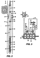
- FIG.1 schematically represents a cross-section of earth 10 along the length of a wellbore penetration 11.
- the wellbore will be at least partially filled with a mixture of liquids including water, drilling fluid, and formation fluids that are indigenous to the earth formations penetrated by the wellbore.
- wellbore fluids such fluid mixtures are referred to as "wellbore fluids”.
- formation fluid hereinafter refers to a specific formation fluid exclusive of any substantial mixture or contamination by fluids not naturally present in the specific formation.
- a formation fluid sampling tool 20 Suspended within the wellbore 11 at the bottom end of a wireline 12 is a formation fluid sampling tool 20.
- the wireline 12 is often carried over a pulley 13 supported by a derrick 14. Wireline deployment and retrieval is performed by a powered winch carried by a service truck 15, for example.
- FIG. 2 an exemplary embodiment of a sampling tool 20 is schematically illustrated by FIG. 2 .
- the sampling tools comprise a serial assembly of several tool segments that are joined end-to-end by the threaded sleeves of mutual compression unions 23.
- An assembly of tool segments appropriate for the present invention may include a hydraulic power unit 21 and a formation fluid extractor 23. Below the extractor 23, a large displacement volume motor/pump unit 24 is provided for line purging. Below the large volume pump is a similar motor/pump unit 25 having a smaller displacement volume that is quantitatively monitored as described more expansively with respect to FIG. 3 . Ordinarily, one or more sample tank magazine sections 26 are assembled below the small volume pump. Each magazine section 26 may have three or more fluid sample tanks 30.
- the formation fluid extractor 22 comprises an extensible suction probe 27 that is opposed by bore wall feet 28. Both, the suction probe 27 and the opposing feet 28 are hydraulically extensible to firmly engage the wellbore walls. Construction and operational details of the fluid extraction tool 22 are more expansively described by U.S. Patent No. 5,303,775 , the specification of which is incorporated herewith.
- the mains sample chamber 414 is in fluid communication with the micro sample 510 chamber through flow line 410.
- Sample input 412 receive formation fluid from pump 25.
- Piston 416 is biased with hydrostatic pressure via orifice 420 which is open to the borehole.
- sample fluid from the formation is pumped into the main sample chamber and the micro sample chambers 510 against hydrostatic pressure from the wellbore.
- a nitrogen bias is also supplied in chamber 418 which applies pressure to the back side of piston 416 once piston travels down to abut connecting rod 449. The nitrogen gas charge applies pressure to the sample contained in main sample chamber 414 and micro sample chambers 510.
- Hydrostatic chamber 422 applies hydrostatic pressure underneath piston 416 which keeps the sample fluid being pumped into main sample chamber and micro sample chambers above hydrostatic pressure.
- the micro sample assemblies 400 are housed in tool body 440 from which the micro sample assemblies 400 can be removed for inspection and testing of the sample inside of micro sample chamber 510.
- a valve 516 is open to provide fluid communication between the main sample chamber 414 and the micro sample chambers 510.
- the micro sample chambers 510 are provided with biasing pistons 441 which are open to the bore hole hydrostatic pressure via orifice 522.
- the formation fluid is pumped into sample flow line 410 and is opposed by hydrostatic pressure by pistons 441 in the micro sample chambers 510 and piston 416 in the main sample chamber 414.
- the micro sample assembly 400 is weighed before a run while it is empty and weighed again after being filled with sample fluid to determine the weight of the sample fluid. Knowing the volume of the micro sample chamber 510, a density for the fluid sample inside for the micro sample chamber 510 is determined by dividing the weight (mass) by the volume. The sample fluid density can be used to determine fluid viscosity.
- Flow line 410 enable formation fluid to enter micro sample chamber 510 via check valve 520.
- Check valve 520 allows formation fluid to enter into the sample chamber but does not allow fluid to exit unless the check valve is opened with a pin 612 as shown in Fig. 6 .
- Valve 516 is closed after the sample fills micro sample chambers 510 and main sample chamber 414 so that pistons 414 and 416 respectively have bottomed out to expand the respective sample chambers to maximum volume.
- purge line 512 is opened to relieve the pressure in flow line 410 between valve 516 and check valve 520. Relieving this pressure enables removal of micro sample assembly 400 by unscrewing the assembly threads 532 from tool body 518, so that the sample inside of the micro sample assembly 400 contained in micro sample chamber 510 can be visually inspected and analyzed.
- Micro sample assembly 400 can be made of metal with windows made of a material such as sapphire the enables visual inspection and optical analysis of the contents of the micro sample chamber.
- the entire micro sample assembly 400 or chamber walls 401 surrounding micro sample chamber 510 can be made of a material such as sapphire the enables visual inspection and optical analysis of the contents of the micro sample chamber.
- a water pump can be connected to orifice 522 to apply pressure to the back side of micro sample assembly piston 441 to pressurize sample in sample chamber 510 during transfer of the micro sample into a test apparatus, such as a gas chromatograph 600.
- the micro sample assembly screws into the test block 600 and pin 612 engages check valve 520 to allow the sample inside or sample chamber 510 to enter test block 600.
- the water pressure from pump 610 keeps the sample under pressure to prevent flashing of the sample inside of the sample chamber 510 during transfer to the test block.
- the present example of the micro sample chamber provides one or more optical conduits, which in this example are high-pressure sapphire windows 530 for ingress and egress of electromagnetic energy into the micro sample chamber 510 for optical analysis of parameters of interest for formation fluid sample 510.
- the entire micro sample chamber can be made of sapphire or another material which enables electromagnetic energy to pass through the material, thereby enabling visual inspection and noninvasive spectral and other analysis of the contents of the micro sample chamber.
- Optical conduits other than a sapphire window are acceptable.
- the micro sample assembly is removed from a sample tank carrier.
- An external optical analyzer 620 comprising an NIR/MIR ultraviolet or visible light source and spectrometers provided for surface non-invasive analysis.
- the optical analyzer 620 is comprises a NIR/MIR light source a and a NIR/MIR light sensor for analysis of light transmittance, fluorescence and total attenuated reflectance. That is, without disturbing the fluid sample or requiring transferring the sample to another Department of Transportation (DOT) approved chamber for transport to an off-site laboratory for analysis.
- DOT Department of Transportation
- the external optical analyzer 620 in the current example uses wavelength ranges from 1500 nm to 2000 nm to scan the fluid sample to determine or estimate through soft modeling techniques, parameters of interest, such as sample contamination percentage, gas oil ratio (GOR), density and asphaltene deposition pressure.
- a tunable diode laser and a Raman spectrometer are also provided in analysis module 620 for spectral analysis of the fluid sample.
- Each of the light sources and sensors are located inside of the micro sample chamber 510 or communicate with the interior of the micro sample chamber via the optical window 530 or an equivalent optical conduit providing data or electromagnetic energy ingress and egress to the interior of the sample tank and the sample retained therein.
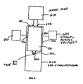
- FIG. 8 Some of the numerous advantages of the present invention are shown by comparison to FIG. 7 , a prior art system and FIG. 8 , the new method and apparatus design provided by the AOA of the present invention. Note that in FIG. 8 that a primary parameter calculation by optical techniques 1114 is available immediately or in less than six hours and a final PVT report 1132 in less than a week or less rather than six to eight weeks as shown in FIG. 7 for the prior art system.
- An advantage for the disclosed method and apparatus is that no sample transfer is required, as non-invasive surface or down hole equipment in external equipment 620 perform PVT and spectral analysis to determine asphaltene deposition, bubble point, formation volume factor, compositional analysis and additional analysis described herein.
- the method and apparatus of the present invention is implemented as a set computer executable of instructions on a computer readable medium, comprising ROM, RAM, CD-ROM, Flash RAM or any other computer readable medium, now known or unknown that when executed cause a computer to implement the functions of the present invention.
Landscapes
- Life Sciences & Earth Sciences (AREA)
- Physics & Mathematics (AREA)
- Health & Medical Sciences (AREA)
- Chemical & Material Sciences (AREA)
- General Physics & Mathematics (AREA)
- Biochemistry (AREA)
- Engineering & Computer Science (AREA)
- Pathology (AREA)
- Analytical Chemistry (AREA)
- General Health & Medical Sciences (AREA)
- Immunology (AREA)
- General Life Sciences & Earth Sciences (AREA)
- Spectroscopy & Molecular Physics (AREA)
- Mining & Mineral Resources (AREA)
- Geology (AREA)
- Food Science & Technology (AREA)
- Fluid Mechanics (AREA)
- Medicinal Chemistry (AREA)
- Oil, Petroleum & Natural Gas (AREA)
- Geophysics (AREA)
- Hydrology & Water Resources (AREA)
- Environmental & Geological Engineering (AREA)
- Nuclear Medicine, Radiotherapy & Molecular Imaging (AREA)
- General Chemical & Material Sciences (AREA)
- Chemical Kinetics & Catalysis (AREA)
- Geochemistry & Mineralogy (AREA)
- Investigating, Analyzing Materials By Fluorescence Or Luminescence (AREA)
- Sampling And Sample Adjustment (AREA)
- Investigating Or Analysing Materials By Optical Means (AREA)
- Optical Measuring Cells (AREA)
Description
- The present invention relates generally to the field of downhole sampling analysis and in particular to obtaining an aliquot formation fluid micro sample down hole for rapid analysis on location to determine the quality of the down hole sample.
- Earth formation fluids in a hydrocarbon producing well typically comprise a mixture of oil, gas, and water. The pressure, temperature and volume of formation fluids control the phase relation of these constituents. In a subsurface formation, high well fluid pressures often entrain gas within 1110 oil above the bubble point pressure. When the press is reduced, the entrained or dissolved gaseous compounds separate from the liquid phase sample. The accurate measurement of pressure, temperature, and formation fluid composition from a particular well affects the commercial viability for producing fluids available from the well. The data also provides information regarding procedures for maximizing the completion and production of the respective hydrocarbon reservoir.
- Certain techniques analyze the well fluids downhole in the well bore. United States Patent No.
6,467,544 to Brown, et al . describes a sample chamber having a slidably disposed piston to define a sample cavity on one side of the piston and a buffer cavity on the other side of the piston. United States Patent No.5,361,839 to Griffith et al. (1993 ) disclosed a transducer for generating an output representative of fluid sample characteristics downhole in a wellbore. United States Patent No.5,329,811 to Schultz et al. (I 994 ) disclosed an apparatus and method for assessing pressure and volume data for a downhole well fluid sample. - Other techniques capture a well fluid sample for retrieval to the surface. United States Patent No.
4,583,595 to Czenichow et al. (1986 ) disclosed a piston actuated mechanism for capturing a well fluid sample. United States Patent No.4,721,157 to Berzin (1988 ) disclosed a shifting valve sleeve for capturing a well fluid sample in a chamber. United States Patent No.4,766,955 to Petermann (1988 ) disclosed a piston engaged with a control valve for capturing a well fluid sample, and United States Patent No.4,903,765 to Zunkel (1990 ) disclosed a time-delayed well fluid sampler. United States Patent No.5,009,100 to Gruber et al. (1991 ) disclosed a wireline sampler for collecting a well fluid sample from a selected wellbore depth. United States Patent No.5,240,072 to Schultz et al. (1993 ) disclosed a multiple sample annulus pressure responsive sampler for permitting well fluid sample collection at different time and depth intervals, and United States Patent No.5,322,120 to Be et al. (1994 ) disclosed an electrically actuated hydraulic system for collecting well fluid samples deep in a wellbore. - Temperatures downhole in a deep wellbore often exceed 300 degrees F. When a hot formation fluid sample is retrieved to the surface at 70 degrees F, the resulting drop in temperature causes the formation fluid sample to contract. If the volume of the sample is unchanged, such contraction substantially reduces the sample pressure. A pressure drop causes changes in the situ formation fluid parameters, and can permit phase separation between liquids and gases entrained within the formation fluid sample. Phase separation significantly changes the formation fluid characteristics, and reduces the ability to evaluate the actual properties of the formation fluid.
- To overcome this limitation, various techniques have been developed to maintain pressure of the formation fluid sample. United States Patent No.
5,337,822 to Massie et al. (1994 ) pressurized a formation fluid sample with a hydraulically driven piston powered by a high pressure gas. Similarly, United States Patent No.5,622,166 to Shammai (1997 ) used a pressurized gas to charge the formation fluid sample. United States Patent Nos.5,303,775 (1994 ) and5,377,755 (1995) to Michaels et al . disclosed a bi-directional, positive displacement pump for increasing the formation fluid sample pressure above the bubble point so that subsequent cooling did not reduce the fluid pressure below the bubble point. - Typically, sample tanks are transported to laboratories for analysis for determination of formation fluid properties based on the sample. The samples typically have to be transferred to a transportation tank, thus risking sample damage and spoilage due to pressure loss and formation of bubbles or asphaltene precipitation within the sample. Moreover, even if the sample is transferred successfully to the laboratory, it typically takes weeks or months to receive a full laboratory analysis of the sample. Thus, there is a need for a rapid sample analysis system that provides accurate results and eliminates the risk of sample spoilage.
US 5, 939,717 discloses a previously-considered downhole tool for determining a parameter of interest of a fluid sample. - According to one aspect of the present invention, there is provided a downhole tool for determining a parameter of interest of a fluid sample, the tool comprising a main sample chamber, and, a micro sample chamber, an analyzer for analyzing the fluid sample downhole and associated with the micro sample chamber; the tool characterized in that: a micro sample chamber, and the micro sample chamber, the main sample chamber and the fluid sample are in fluid communication downhole, and the main sample chamber is adapted to contain a first portion of the fluid sample and the micro sample chamber is adapted to contain a second portion of the fluid sample, and in that the micro sample chamber is removable from a body of the downhole tool for determining the parameter of interest for the second portion of the fluid thereby to determine the parameter of interest for the first portion of the fluid sample.
- According to another aspect of the present invention, there is provided a method for determining a parameter of interest for a fluid sample, the method characterized by: filling a main sample chamber and a micro sample chamber in fluid communication with the fluid sample and with one another, thereby containing a first portion of the fluid sample in the main sample chamber, and containing a second portion of the formation fluid sample in the micro sample chamber; and analyzing the second portion of the fluid sample in the micro sample chamber with an analyzer associated with the micro sample chamber to determine a parameter of interest for the first portion of the fluid sample in the main sample chamber.
- The present invention addresses the shortcomings of the related art described above. The present invention provides a downhole sample tank and a plurality of micro sample chambers. The micro sample chambers can have at least one window for introduction of visible, near-infrared (NIR), mid-infrared (MIR) and other electromagnetic energy into the tank for samples collected in the micro sample chamber downhole from an earth boring or well bore. The window is made of sapphire or another material capable of allowing electromagnetic energy to pass through the window. The entire micro sample chamber can be made of sapphire or another material capable of allowing electromagnetic energy to pass another material enabling visual inspection or analysis of the sample inside the micro sample chamber. The micro sample chamber enables immediate testing of the sample on location at the surface to determine the quality of the sample in the main sample tank or to enable comprehensive testing of the sample.
- The sample tank and micro sample chambers filled by pumping formation fluid against a piston biased against hydrostatic pressure. The sample tank and micro sample chambers are over pressurized by pumping or a gas charge to raise the sample pressure to a pressure above the bubble point pressure for the sample to prevent adverse pressure drop. The micro sample chambers can be removed at the surface for immediate testing via optical analysis of the sample intact inside of the micro sample chamber or by affixing the micro sample chamber to test block for pumping the sample from the micro sample chamber into the test block for gas chromatography testing. A biasing water pressure charge can be applied to the micro sample to further ensure that the micro sample remains above the bubble point pressure. The viscosity of the sample inside of the micro sample tank can be determined by weighing the micro sample tank empty and again after it is filled with the sample to determine the weight of the sample inside the known volume of the micro sample chamber.
- For detailed understanding of the present invention, references should be made to the following detailed description of the exemplary embodiment, taken in conjunction with the accompanying drawings, in which like elements have been given like numerals,
wherein: -
FIG.1 is a schematic earth section illustrating the invention operating environment; -
FIG. 2 is a schematic of the invention in operative assembly with cooperatively supporting tools; -
FIG. 3 is a schematic of a representative formation fluid extraction and delivery system; -
FIG. 4 is an illustration of an exemplary micro sample chamber; -
FIG. 5 is a more detailed illustration of the micro sample chambers ofFig. 4 with a check valve and a purge line; -
Fig. 6 illustrates the micro sample assembly disconnected from the down hole tool and undergoing analysis of the micros sample; -
FIG. 7 is an illustration of a common known analysis procedure; and -
FIG. 8 is an illustration of the new improved procedure provided by the present invention. -
FIG.1 schematically represents a cross-section ofearth 10 along the length of awellbore penetration 11. Usually, the wellbore will be at least partially filled with a mixture of liquids including water, drilling fluid, and formation fluids that are indigenous to the earth formations penetrated by the wellbore. Hereinafter, such fluid mixtures are referred to as "wellbore fluids". The term "formation fluid" hereinafter refers to a specific formation fluid exclusive of any substantial mixture or contamination by fluids not naturally present in the specific formation. - Suspended within the
wellbore 11 at the bottom end of awireline 12 is a formationfluid sampling tool 20. Thewireline 12 is often carried over apulley 13 supported by aderrick 14. Wireline deployment and retrieval is performed by a powered winch carried by aservice truck 15, for example. - Pursuant to the present invention, an exemplary embodiment of a
sampling tool 20 is schematically illustrated byFIG. 2 . In the present example, the sampling tools comprise a serial assembly of several tool segments that are joined end-to-end by the threaded sleeves ofmutual compression unions 23. An assembly of tool segments appropriate for the present invention may include ahydraulic power unit 21 and aformation fluid extractor 23. Below theextractor 23, a large displacement volume motor/pump unit 24 is provided for line purging. Below the large volume pump is a similar motor/pump unit 25 having a smaller displacement volume that is quantitatively monitored as described more expansively with respect toFIG. 3 . Ordinarily, one or more sampletank magazine sections 26 are assembled below the small volume pump. Eachmagazine section 26 may have three or morefluid sample tanks 30. - The formation fluid extractor 22 comprises an
extensible suction probe 27 that is opposed bybore wall feet 28. Both, thesuction probe 27 and the opposingfeet 28 are hydraulically extensible to firmly engage the wellbore walls. Construction and operational details of the fluid extraction tool 22 are more expansively described byU.S. Patent No. 5,303,775 , the specification of which is incorporated herewith. - Turning now to
FIG. 4 , themains sample chamber 414 is in fluid communication with themicro sample 510 chamber throughflow line 410. Sample input 412 receive formation fluid frompump 25.Piston 416 is biased with hydrostatic pressure viaorifice 420 which is open to the borehole. Thus, sample fluid from the formation is pumped into the main sample chamber and themicro sample chambers 510 against hydrostatic pressure from the wellbore. As more fluid is pumped into thesample chamber 414, the volume ofsample chamber 414 expands, as does the volume ofmicro sample chambers 510. A nitrogen bias is also supplied in chamber 418 which applies pressure to the back side ofpiston 416 once piston travels down to abut connecting rod 449. The nitrogen gas charge applies pressure to the sample contained inmain sample chamber 414 andmicro sample chambers 510. -
Hydrostatic chamber 422 applies hydrostatic pressure underneathpiston 416 which keeps the sample fluid being pumped into main sample chamber and micro sample chambers above hydrostatic pressure. Themicro sample assemblies 400 are housed intool body 440 from which themicro sample assemblies 400 can be removed for inspection and testing of the sample inside ofmicro sample chamber 510. - Turning now to
Fig. 5 , a more detailed illustration of themicro sample assembly 400 is shown. Avalve 516 is open to provide fluid communication between themain sample chamber 414 and themicro sample chambers 510. Themicro sample chambers 510 are provided with biasingpistons 441 which are open to the bore hole hydrostatic pressure viaorifice 522. Thus, the formation fluid is pumped intosample flow line 410 and is opposed by hydrostatic pressure bypistons 441 in themicro sample chambers 510 andpiston 416 in themain sample chamber 414. - The
micro sample assembly 400 is weighed before a run while it is empty and weighed again after being filled with sample fluid to determine the weight of the sample fluid. Knowing the volume of themicro sample chamber 510, a density for the fluid sample inside for themicro sample chamber 510 is determined by dividing the weight (mass) by the volume. The sample fluid density can be used to determine fluid viscosity. -
Flow line 410 enable formation fluid to entermicro sample chamber 510 viacheck valve 520.Check valve 520 allows formation fluid to enter into the sample chamber but does not allow fluid to exit unless the check valve is opened with apin 612 as shown inFig. 6 . -
Valve 516 is closed after the sample fillsmicro sample chambers 510 andmain sample chamber 414 so thatpistons valve 516 is closed,purge line 512 is opened to relieve the pressure inflow line 410 betweenvalve 516 andcheck valve 520. Relieving this pressure enables removal ofmicro sample assembly 400 by unscrewing theassembly threads 532 from tool body 518, so that the sample inside of themicro sample assembly 400 contained inmicro sample chamber 510 can be visually inspected and analyzed. -
Micro sample assembly 400 can be made of metal with windows made of a material such as sapphire the enables visual inspection and optical analysis of the contents of the micro sample chamber. The entiremicro sample assembly 400 or chamber walls 401 surroundingmicro sample chamber 510 can be made of a material such as sapphire the enables visual inspection and optical analysis of the contents of the micro sample chamber. - Turning now to
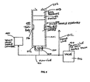
Fig. 6 , a water pump can be connected to orifice 522 to apply pressure to the back side of microsample assembly piston 441 to pressurize sample insample chamber 510 during transfer of the micro sample into a test apparatus, such as agas chromatograph 600. The micro sample assembly screws into thetest block 600 andpin 612 engagescheck valve 520 to allow the sample inside orsample chamber 510 to entertest block 600. The water pressure frompump 610 keeps the sample under pressure to prevent flashing of the sample inside of thesample chamber 510 during transfer to the test block. - The present example of the micro sample chamber provides one or more optical conduits, which in this example are high-
pressure sapphire windows 530 for ingress and egress of electromagnetic energy into themicro sample chamber 510 for optical analysis of parameters of interest forformation fluid sample 510. The entire micro sample chamber can be made of sapphire or another material which enables electromagnetic energy to pass through the material, thereby enabling visual inspection and noninvasive spectral and other analysis of the contents of the micro sample chamber. Optical conduits other than a sapphire window are acceptable. - In surface operations, as shown in
FIG. 6 , the micro sample assembly is removed from a sample tank carrier. An externaloptical analyzer 620 comprising an NIR/MIR ultraviolet or visible light source and spectrometers provided for surface non-invasive analysis. Theoptical analyzer 620 is comprises a NIR/MIR light source a and a NIR/MIR light sensor for analysis of light transmittance, fluorescence and total attenuated reflectance. That is, without disturbing the fluid sample or requiring transferring the sample to another Department of Transportation (DOT) approved chamber for transport to an off-site laboratory for analysis. - The external
optical analyzer 620 in the current example uses wavelength ranges from 1500 nm to 2000 nm to scan the fluid sample to determine or estimate through soft modeling techniques, parameters of interest, such as sample contamination percentage, gas oil ratio (GOR), density and asphaltene deposition pressure. A tunable diode laser and a Raman spectrometer are also provided inanalysis module 620 for spectral analysis of the fluid sample. Each of the light sources and sensors are located inside of themicro sample chamber 510 or communicate with the interior of the micro sample chamber via theoptical window 530 or an equivalent optical conduit providing data or electromagnetic energy ingress and egress to the interior of the sample tank and the sample retained therein. - Some of the numerous advantages of the present invention are shown by comparison to
FIG. 7 , a prior art system andFIG. 8 , the new method and apparatus design provided by the AOA of the present invention. Note that inFIG. 8 that a primary parameter calculation byoptical techniques 1114 is available immediately or in less than six hours and afinal PVT report 1132 in less than a week or less rather than six to eight weeks as shown inFIG. 7 for the prior art system. An advantage for the disclosed method and apparatus is that no sample transfer is required, as non-invasive surface or down hole equipment inexternal equipment 620 perform PVT and spectral analysis to determine asphaltene deposition, bubble point, formation volume factor, compositional analysis and additional analysis described herein. - In another embodiment, the method and apparatus of the present invention is implemented as a set computer executable of instructions on a computer readable medium, comprising ROM, RAM, CD-ROM, Flash RAM or any other computer readable medium, now known or unknown that when executed cause a computer to implement the functions of the present invention.
- While the foregoing disclosure is directed to the exemplary embodiments of the invention various modifications will be apparent to those skilled in the art. It is intended that all variations within the scope of the appended claims be embraced by the foregoing disclosure. Examples of the more important features of the invention have been summarized rather broadly in order that the detailed description thereof that follows may be better understood, and in order that the contributions to the art may be appreciated. There are, of course, additional features of the invention that will be described hereinafter and which will form the subject of the claims appended hereto.
Claims (28)
- A downhole tool (20) for determining a parameter of interest of a fluid sample, the tool comprising a main sample chamber (414), and, a micro sample chamber (510), an analyzer for analyzing the fluid sample downhole and associated with the micro sample chamber (510), the tool characterized in that:the micro sample chamber (510), the main sample chamber (414), and the fluid sample are in fluid communication downhole, andin that the main sample chamber (414) is adapted to contain a first portion of the fluid sample and the micro sample chamber (510) is adapted to contain a second portion of the fluid sample, andin that the micro sample chamber (510) is removable from a body of the downhole tool (20) for determining the parameter of interest for the second portion of the fluid, thereby to determine the parameter of interest for the first portion of the fluid sample.
- The apparatus of claim 1, further characterized in that the micro sample chamber (510) has a known weight and volume for determining density of the fluid sample.
- The apparatus of claim 1, further characterized in that the entire micro sample chamber (510) is made of a material that allows passage of electromagnetic energy for analysis of the sample in the micro sample chamber (510).
- The apparatus of claim 1, further characterized by:a pressure charge for maintaining a pressure on the fluid in the micro sample chamber (510) sample during egress of the tool from a wellbore.
- The apparatus of claim 1, further characterized in that the analyzer comprises at least one of the set consisting of a tunable diode laser, an infrared light source and infrared sensor, and a Raman spectrometer for analyzing the fluid sample.
- The apparatus of claim 5, further characterized by:a micro sample chamber piston for opposing the fluid from a sample pump during filling of the micro sample chamber with the fluid sample.
- The apparatus of claim 1, further characterized by:a water pressure charge for pressurizing the sample in the micro sample chamber after egress from down hole.
- The apparatus of claim 1, further characterized by:a check valve that admits fluid into the micro sample chamber and prevents the fluid from exiting the micro sample chamber.
- The apparatus of claim 8, further characterized by:a valve for isolating the micro sample chamber from the main sample chamber.
- The apparatus of claim 9, further characterized by:a purge line for relieving pressure between the micro sample chamber and the main sample chamber.
- The apparatus of claim 1, further characterized in that substantially the entire micro sample chamber (510) is made of a material to enable visual inspection of the sample inside of the micro sample chamber (510).
- The apparatus of claim 1, further characterized in that the micro sample chamber (510) is made of a material to enable optical analysis of the sample inside of the micro sample chamber (510).
- The apparatus of claim 1, further characterized in that the micro sample chamber (510) is removable from the tool for analysis of the sample at the surface by external analysis equipment.
- The apparatus of claim 1, further characterized in that the micro sample chamber (510) is removable from the micro sample chamber for analysis of the micro sample fluid sample at a surface.
- A method for determining a parameter of interest for a fluid sample, the method characterized by:filling a main sample chamber (414) and a micro sample chamber (510) in fluid communication with the fluid sample and with one another, thereby containing a first portion of the fluid sample in the main sample chamber (414), and containing a second portion of the formation fluid sample in the micro sample chamber (510); andanalyzing the second portion of the fluid sample in the micro sample chamber (510) with an analyzer associated with the micro sample chamber (510) to determine a parameter of interest for the first portion of the fluid sample in the main sample chamber (414).
- The method of claim 15, further characterized in that analyzing the second portion of the fluid further comprises:weighing the micro sample chamber (510) containing the second portion of the fluid sample;determining the weight of the second portion of the fluid in the micro sample chamber (510) from the weight of the micro sample chamber (510) containing the second portion of the fluid minus a weight of the micro sample chamber (510) when empty; and determining at least one of the set consisting of density and viscosity of the fluid from the weight of the fluid and the volume of the sample chamber containing the fluid.
- The method of claim 15, further characterized in that substantially the entire micro sample chamber (510) is made of a material that allows passage of electromagnetic energy for analysis of the sample in the micro sample chamber.
- The method of claim 15, further characterized by:maintaining a pressure on the second portion of the fluid in the micro sample chamber (510) with a pressure charge during egress of the tool from the well bore.
- The method of claim 15, further characterized by:applying a hydrostatic pressure bias acting on a sample inside of the micro sample chamber (510).
- The method of claim 15, further characterized by:opposing a sample pump during filling of the micro sample chamber (510) with the second portion of the fluid sample.
- The method of claim 15, further characterized by:pressurizing the sample in the micro sample chamber (510) after egress from down hole.
- The method of claim 15, further characterized by:admitting fluid into the micro sample chamber (510) and preventing fluid from exiting the micro sample chamber with a check valve.
- The method of claim 15, further characterized by:a valve for isolating the micro sample chamber (510) from the main sample chamber.
- The method of claim 23, further characterized by:relieving pressure between the micro sample chamber (510) and the main sample chamber (414).
- The method of claim 15, further characterized by:visually inspecting the fluid sample inside of the micro sample chamber (510).
- The method of claim 15, further characterized by:optically analyzing the second portion of the fluid sample inside of the micro sample chamber (510).
- The method of claim 15, further characterized by:removing the micro sample chamber (510) from the tool; andanalyzing the second portion of the fluid sample inside of the micro sample chamber (510) at the surface by external analysis equipment to determine the quality of the first portion of the fluid sample inside of the main sample chamber (414).
- The method of claim 15, further characterized by:removing the sample from the micro sample chamber for analysis of the second portion of the fluid sample at the surface by external analysis equipment to determine a parameter of interest for the first portion of the fluid sample inside of the main chamber.
Applications Claiming Priority (2)
| Application Number | Priority Date | Filing Date | Title |
|---|---|---|---|
| US46766803P | 2003-05-02 | 2003-05-02 | |
| PCT/US2004/013552 WO2004099564A2 (en) | 2003-05-02 | 2004-05-03 | A method and apparatus for a downhole micro-sampler |
Publications (2)
| Publication Number | Publication Date |
|---|---|
| EP1623091A2 EP1623091A2 (en) | 2006-02-08 |
| EP1623091B1 true EP1623091B1 (en) | 2009-04-01 |
Family
ID=33435101
Family Applications (3)
| Application Number | Title | Priority Date | Filing Date |
|---|---|---|---|
| EP04750868A Expired - Lifetime EP1631732B1 (en) | 2003-05-02 | 2004-04-29 | A method and apparatus for an advanced optical analyzer |
| EP10175791.2A Expired - Lifetime EP2320026B1 (en) | 2003-05-02 | 2004-04-29 | A method and apparatus for a downhole micro-sampler |
| EP04751109A Expired - Lifetime EP1623091B1 (en) | 2003-05-02 | 2004-05-03 | A method and apparatus for a downhole micro-sampler |
Family Applications Before (2)
| Application Number | Title | Priority Date | Filing Date |
|---|---|---|---|
| EP04750868A Expired - Lifetime EP1631732B1 (en) | 2003-05-02 | 2004-04-29 | A method and apparatus for an advanced optical analyzer |
| EP10175791.2A Expired - Lifetime EP2320026B1 (en) | 2003-05-02 | 2004-04-29 | A method and apparatus for a downhole micro-sampler |
Country Status (10)
| Country | Link |
|---|---|
| US (2) | US7210343B2 (en) |
| EP (3) | EP1631732B1 (en) |
| JP (1) | JP2007535655A (en) |
| CN (1) | CN1784535B (en) |
| BR (1) | BRPI0410046A (en) |
| CA (1) | CA2524075A1 (en) |
| DE (1) | DE602004012554T2 (en) |
| NO (1) | NO20055319L (en) |
| RU (1) | RU2333357C2 (en) |
| WO (2) | WO2004099566A1 (en) |
Families Citing this family (126)
| Publication number | Priority date | Publication date | Assignee | Title |
|---|---|---|---|---|
| RU2348806C2 (en) * | 2003-05-02 | 2009-03-10 | Бейкер Хьюз Инкорпорейтед | Continuous data recorder for downhole sample cylinder |
| US7782460B2 (en) * | 2003-05-06 | 2010-08-24 | Baker Hughes Incorporated | Laser diode array downhole spectrometer |
| US7196786B2 (en) * | 2003-05-06 | 2007-03-27 | Baker Hughes Incorporated | Method and apparatus for a tunable diode laser spectrometer for analysis of hydrocarbon samples |
| US20070081157A1 (en) * | 2003-05-06 | 2007-04-12 | Baker Hughes Incorporated | Apparatus and method for estimating filtrate contamination in a formation fluid |
| US7408645B2 (en) * | 2003-11-10 | 2008-08-05 | Baker Hughes Incorporated | Method and apparatus for a downhole spectrometer based on tunable optical filters |
| US7490664B2 (en) * | 2004-11-12 | 2009-02-17 | Halliburton Energy Services, Inc. | Drilling, perforating and formation analysis |
| US7565835B2 (en) | 2004-11-17 | 2009-07-28 | Schlumberger Technology Corporation | Method and apparatus for balanced pressure sampling |
| US7546885B2 (en) * | 2005-05-19 | 2009-06-16 | Schlumberger Technology Corporation | Apparatus and method for obtaining downhole samples |
| EP1736756A1 (en) * | 2005-06-20 | 2006-12-27 | Bp Oil International Limited | Development of disposable/Sealable tips for near infra-red (NIR) spectroscopic probes |
| US7475593B2 (en) | 2005-06-24 | 2009-01-13 | Precision Energy Services, Inc. | High temperature near infrared for measurements and telemetry in well boreholes |
| US7874206B2 (en) | 2005-11-07 | 2011-01-25 | Halliburton Energy Services, Inc. | Single phase fluid sampling apparatus and method for use of same |
| US8429961B2 (en) | 2005-11-07 | 2013-04-30 | Halliburton Energy Services, Inc. | Wireline conveyed single phase fluid sampling apparatus and method for use of same |
| US7472589B2 (en) | 2005-11-07 | 2009-01-06 | Halliburton Energy Services, Inc. | Single phase fluid sampling apparatus and method for use of same |
| US7596995B2 (en) | 2005-11-07 | 2009-10-06 | Halliburton Energy Services, Inc. | Single phase fluid sampling apparatus and method for use of same |
| US7428925B2 (en) * | 2005-11-21 | 2008-09-30 | Schlumberger Technology Corporation | Wellbore formation evaluation system and method |
| US7681450B2 (en) * | 2005-12-09 | 2010-03-23 | Baker Hughes Incorporated | Casing resonant radial flexural modes in cement bond evaluation |
| US20080087470A1 (en) | 2005-12-19 | 2008-04-17 | Schlumberger Technology Corporation | Formation Evaluation While Drilling |
| US7458257B2 (en) * | 2005-12-19 | 2008-12-02 | Schlumberger Technology Corporation | Downhole measurement of formation characteristics while drilling |
| US7367394B2 (en) * | 2005-12-19 | 2008-05-06 | Schlumberger Technology Corporation | Formation evaluation while drilling |
| US7482811B2 (en) * | 2006-11-10 | 2009-01-27 | Schlumberger Technology Corporation | Magneto-optical method and apparatus for determining properties of reservoir fluids |
| US20080111064A1 (en) * | 2006-11-10 | 2008-05-15 | Schlumberger Technology Corporation | Downhole measurement of substances in earth formations |
| US7586087B2 (en) * | 2007-01-24 | 2009-09-08 | Schlumberger Technology Corporation | Methods and apparatus to characterize stock-tank oil during fluid composition analysis |
| US20090066959A1 (en) * | 2007-09-07 | 2009-03-12 | Baker Hughes Incorporated | Apparatus and Method for Estimating a Property of a Fluid in a Wellbore Using Photonic Crystals |
| US8028562B2 (en) * | 2007-12-17 | 2011-10-04 | Schlumberger Technology Corporation | High pressure and high temperature chromatography |
| US8794350B2 (en) * | 2007-12-19 | 2014-08-05 | Bp Corporation North America Inc. | Method for detecting formation pore pressure by detecting pumps-off gas downhole |
| US20090159334A1 (en) * | 2007-12-19 | 2009-06-25 | Bp Corporation North America, Inc. | Method for detecting formation pore pressure by detecting pumps-off gas downhole |
| US8297351B2 (en) * | 2007-12-27 | 2012-10-30 | Schlumberger Technology Corporation | Downhole sensing system using carbon nanotube FET |
| US7886821B2 (en) * | 2008-01-24 | 2011-02-15 | Baker Hughes Incorporated | Apparatus and method for determining fluid properties |
| US8032311B2 (en) | 2008-05-22 | 2011-10-04 | Baker Hughes Incorporated | Estimating gas-oil ratio from other physical properties |
| US9074422B2 (en) | 2011-02-24 | 2015-07-07 | Foro Energy, Inc. | Electric motor for laser-mechanical drilling |
| US9089928B2 (en) | 2008-08-20 | 2015-07-28 | Foro Energy, Inc. | Laser systems and methods for the removal of structures |
| US9027668B2 (en) | 2008-08-20 | 2015-05-12 | Foro Energy, Inc. | Control system for high power laser drilling workover and completion unit |
| US9347271B2 (en) | 2008-10-17 | 2016-05-24 | Foro Energy, Inc. | Optical fiber cable for transmission of high power laser energy over great distances |
| US10301912B2 (en) * | 2008-08-20 | 2019-05-28 | Foro Energy, Inc. | High power laser flow assurance systems, tools and methods |
| US9138786B2 (en) | 2008-10-17 | 2015-09-22 | Foro Energy, Inc. | High power laser pipeline tool and methods of use |
| US9360631B2 (en) | 2008-08-20 | 2016-06-07 | Foro Energy, Inc. | Optics assembly for high power laser tools |
| US9669492B2 (en) | 2008-08-20 | 2017-06-06 | Foro Energy, Inc. | High power laser offshore decommissioning tool, system and methods of use |
| US9242309B2 (en) | 2012-03-01 | 2016-01-26 | Foro Energy Inc. | Total internal reflection laser tools and methods |
| US9267330B2 (en) | 2008-08-20 | 2016-02-23 | Foro Energy, Inc. | Long distance high power optical laser fiber break detection and continuity monitoring systems and methods |
| US8627901B1 (en) | 2009-10-01 | 2014-01-14 | Foro Energy, Inc. | Laser bottom hole assembly |
| US8636085B2 (en) | 2008-08-20 | 2014-01-28 | Foro Energy, Inc. | Methods and apparatus for removal and control of material in laser drilling of a borehole |
| US9719302B2 (en) | 2008-08-20 | 2017-08-01 | Foro Energy, Inc. | High power laser perforating and laser fracturing tools and methods of use |
| US8571368B2 (en) | 2010-07-21 | 2013-10-29 | Foro Energy, Inc. | Optical fiber configurations for transmission of laser energy over great distances |
| US9244235B2 (en) | 2008-10-17 | 2016-01-26 | Foro Energy, Inc. | Systems and assemblies for transferring high power laser energy through a rotating junction |
| US9664012B2 (en) | 2008-08-20 | 2017-05-30 | Foro Energy, Inc. | High power laser decomissioning of multistring and damaged wells |
| US9080425B2 (en) | 2008-10-17 | 2015-07-14 | Foro Energy, Inc. | High power laser photo-conversion assemblies, apparatuses and methods of use |
| US8379207B2 (en) * | 2008-10-15 | 2013-02-19 | Baker Hughes Incorporated | Method and apparatus for estimating a fluid property |
| US7967067B2 (en) | 2008-11-13 | 2011-06-28 | Halliburton Energy Services, Inc. | Coiled tubing deployed single phase fluid sampling apparatus |
| EP2449206A2 (en) | 2009-06-29 | 2012-05-09 | Halliburton Energy Services, Inc. | Wellbore laser operations |
| US20110016962A1 (en) * | 2009-07-21 | 2011-01-27 | Baker Hughes Incorporated | Detector for Characterizing a Fluid |
| US8783361B2 (en) | 2011-02-24 | 2014-07-22 | Foro Energy, Inc. | Laser assisted blowout preventer and methods of use |
| US8720584B2 (en) | 2011-02-24 | 2014-05-13 | Foro Energy, Inc. | Laser assisted system for controlling deep water drilling emergency situations |
| US8684088B2 (en) | 2011-02-24 | 2014-04-01 | Foro Energy, Inc. | Shear laser module and method of retrofitting and use |
| US8783360B2 (en) | 2011-02-24 | 2014-07-22 | Foro Energy, Inc. | Laser assisted riser disconnect and method of use |
| US9091151B2 (en) | 2009-11-19 | 2015-07-28 | Halliburton Energy Services, Inc. | Downhole optical radiometry tool |
| US8839871B2 (en) | 2010-01-15 | 2014-09-23 | Halliburton Energy Services, Inc. | Well tools operable via thermal expansion resulting from reactive materials |
| US8306762B2 (en) * | 2010-01-25 | 2012-11-06 | Baker Hughes Incorporated | Systems and methods for analysis of downhole data |
| US8508741B2 (en) * | 2010-04-12 | 2013-08-13 | Baker Hughes Incorporated | Fluid sampling and analysis downhole using microconduit system |
| US9297255B2 (en) * | 2010-06-17 | 2016-03-29 | Halliburton Energy Services, Inc. | Non-invasive compressibility and in situ density testing of a fluid sample in a sealed chamber |
| BR112013000100A2 (en) | 2010-07-08 | 2016-05-17 | Halliburton Energy Services Inc | method, and system for determining the presence of a constituent component in a sample fluid |
| EP2606201A4 (en) | 2010-08-17 | 2018-03-07 | Foro Energy Inc. | Systems and conveyance structures for high power long distance laster transmission |
| US9429014B2 (en) | 2010-09-29 | 2016-08-30 | Schlumberger Technology Corporation | Formation fluid sample container apparatus |
| US20120086454A1 (en) * | 2010-10-07 | 2012-04-12 | Baker Hughes Incorporated | Sampling system based on microconduit lab on chip |
| US8474533B2 (en) | 2010-12-07 | 2013-07-02 | Halliburton Energy Services, Inc. | Gas generator for pressurizing downhole samples |
| US20120145907A1 (en) * | 2010-12-14 | 2012-06-14 | Van Groos August F Koster | Dynamic environmental chamber and methods of radiation analysis |
| US8397800B2 (en) | 2010-12-17 | 2013-03-19 | Halliburton Energy Services, Inc. | Perforating string with longitudinal shock de-coupler |
| US8985200B2 (en) | 2010-12-17 | 2015-03-24 | Halliburton Energy Services, Inc. | Sensing shock during well perforating |
| US8397814B2 (en) | 2010-12-17 | 2013-03-19 | Halliburton Energy Serivces, Inc. | Perforating string with bending shock de-coupler |
| US8393393B2 (en) | 2010-12-17 | 2013-03-12 | Halliburton Energy Services, Inc. | Coupler compliance tuning for mitigating shock produced by well perforating |
| AU2010365401B2 (en) | 2010-12-17 | 2015-04-09 | Halliburton Energy Services, Inc. | Well perforating with determination of well characteristics |
| EP2678512A4 (en) | 2011-02-24 | 2017-06-14 | Foro Energy Inc. | Method of high power laser-mechanical drilling |
| US20120241169A1 (en) | 2011-03-22 | 2012-09-27 | Halliburton Energy Services, Inc. | Well tool assemblies with quick connectors and shock mitigating capabilities |
| FR2973828B1 (en) * | 2011-04-11 | 2014-04-18 | Snf Sas | SET OF MEASURING EQUIPMENT AND REGULATION OF HIGH PRESSURE ONLINE VISCOSITY |
| EP2715887A4 (en) | 2011-06-03 | 2016-11-23 | Foro Energy Inc | Rugged passively cooled high power laser fiber optic connectors and methods of use |
| US9091152B2 (en) | 2011-08-31 | 2015-07-28 | Halliburton Energy Services, Inc. | Perforating gun with internal shock mitigation |
| DE102011086206A1 (en) | 2011-11-11 | 2013-05-16 | Carl Zeiss Ag | Arrangement for determining spectral characteristics of boring fluid under influence of high temperature and mechanical loads at place of occurrence of fluid, has source for polychromatic electromagnetic radiation source and optical unit |
| EP2734829B1 (en) * | 2011-12-14 | 2016-11-23 | Halliburton Energy Services, Inc. | Methods of analyzing a reservoir fluid sample using a multivariate optical element calculation device |
| US8547556B2 (en) * | 2011-12-14 | 2013-10-01 | Halliburton Energy Services, Inc. | Methods of analyzing a reservoir fluid sample using a multivariate optical element calculation device |
| US9057256B2 (en) * | 2012-01-10 | 2015-06-16 | Schlumberger Technology Corporation | Submersible pump control |
| DE102012100794B3 (en) * | 2012-01-31 | 2013-02-28 | Airbus Operations Gmbh | Apparatus and method for detecting contaminants in a hydraulic system |
| US20130213648A1 (en) * | 2012-02-16 | 2013-08-22 | Baker Hughes Incorporated | Optical fluid analyzer sampling tool using open beam optical construction |
| WO2014036430A2 (en) | 2012-09-01 | 2014-03-06 | Foro Energy, Inc. | Reduced mechanical energy well control systems and methods of use |
| US9169705B2 (en) | 2012-10-25 | 2015-10-27 | Halliburton Energy Services, Inc. | Pressure relief-assisted packer |
| US9249656B2 (en) * | 2012-11-15 | 2016-02-02 | Baker Hughes Incorporated | High precision locked laser operating at elevated temperatures |
| US9187999B2 (en) * | 2012-11-30 | 2015-11-17 | Baker Hughes Incorporated | Apparatus and method for obtaining formation fluid samples |
| US9429013B2 (en) | 2013-02-25 | 2016-08-30 | Schlumberger Technology Corporation | Optical window assembly for an optical sensor of a downhole tool and method of using same |
| US9534494B2 (en) * | 2013-02-25 | 2017-01-03 | Schlumberger Technology Corporation | Optical window assemblies |
| US9587486B2 (en) | 2013-02-28 | 2017-03-07 | Halliburton Energy Services, Inc. | Method and apparatus for magnetic pulse signature actuation |
| US10509223B2 (en) | 2013-03-05 | 2019-12-17 | Halliburton Energy Services, Inc. | System, method and computer program product for photometric system design and environmental ruggedization |
| US9726009B2 (en) | 2013-03-12 | 2017-08-08 | Halliburton Energy Services, Inc. | Wellbore servicing tools, systems and methods utilizing near-field communication |
| US20140268156A1 (en) * | 2013-03-13 | 2014-09-18 | Schlumberger Technology Corporation | Method and system for determining bubble point pressure |
| US9284817B2 (en) | 2013-03-14 | 2016-03-15 | Halliburton Energy Services, Inc. | Dual magnetic sensor actuation assembly |
| US20150075770A1 (en) | 2013-05-31 | 2015-03-19 | Michael Linley Fripp | Wireless activation of wellbore tools |
| US9752414B2 (en) | 2013-05-31 | 2017-09-05 | Halliburton Energy Services, Inc. | Wellbore servicing tools, systems and methods utilizing downhole wireless switches |
| US9109434B2 (en) * | 2013-06-09 | 2015-08-18 | Schlumberger Technology Corporation | System and method for estimating oil formation volume factor downhole |
| MX368929B (en) | 2013-09-25 | 2019-10-22 | Halliburton Energy Services Inc | Systems and methods for real time measurement of gas content in drilling fluids. |
| US10415380B2 (en) * | 2013-10-01 | 2019-09-17 | Baker Hughes, A Ge Company, Llc | Sample tank with integrated fluid separation |
| WO2015073606A1 (en) | 2013-11-13 | 2015-05-21 | Schlumberger Canada Limited | Automatic pumping system commissioning |
| MX365729B (en) | 2014-03-07 | 2019-06-12 | Halliburton Energy Services Inc | Formation fluid sampling methods and systems. |
| NO342929B1 (en) * | 2014-04-16 | 2018-09-03 | Vision Io As | inspection Tools |
| US10415370B2 (en) | 2014-08-26 | 2019-09-17 | Halliburton Energy Services, Inc. | Systems and methods for in situ monitoring of cement slurry locations and setting processes thereof |
| GB2547354B (en) | 2014-11-25 | 2021-06-23 | Halliburton Energy Services Inc | Wireless activation of wellbore tools |
| US10211887B2 (en) * | 2015-02-10 | 2019-02-19 | Sony Corporation | Receiver and communication system |
| CN105300902A (en) * | 2015-10-26 | 2016-02-03 | 北京农业信息技术研究中心 | Five-spot differentiated depth drug evaporation high-pass dynamic information acquisition method |
| US10221687B2 (en) | 2015-11-26 | 2019-03-05 | Merger Mines Corporation | Method of mining using a laser |
| US11353422B2 (en) | 2016-10-14 | 2022-06-07 | Halliburton Energy Services, Inc. | In situ treatment of chemical sensors |
| CN107907503B (en) * | 2017-01-17 | 2020-06-05 | 合肥中科富华新材料有限公司 | Multi-chamber laser inspection monitor |
| US10371633B2 (en) | 2017-10-30 | 2019-08-06 | Saudi Arabian Oil Company | Determining a specific gravity of a sample |
| US11598703B2 (en) * | 2018-06-08 | 2023-03-07 | Halliburton Energy Services, Inc. | Apparatus, system and method for mechanical testing under confined conditions |
| US11479373B2 (en) * | 2018-08-14 | 2022-10-25 | Honeybee Robotics, Llc | Sample collection system for interplanetary vehicle |
| US11262298B2 (en) | 2018-08-30 | 2022-03-01 | Caterpillar Inc. | System and method for determining fluid origin |
| WO2020050839A1 (en) | 2018-09-05 | 2020-03-12 | Halliburton Energy Services, Inc. | Two frequency comb fourier spectroscopy for chemcial sensing |
| WO2020112106A1 (en) | 2018-11-28 | 2020-06-04 | Halliburton Energy Services, Inc. | Downhole sample extractors and downhole sample extraction systems |
| CN109667579B (en) * | 2018-12-28 | 2021-07-13 | 中国科学院武汉岩土力学研究所 | A gas-liquid fluid sampling device for deep wells in ultra-low permeability formations |
| US11408282B2 (en) | 2019-05-10 | 2022-08-09 | Baker Hughes Oilfield Operations Llc | Bi-conical optical sensor for obtaining downhole fluid properties |
| US11661845B2 (en) | 2019-05-10 | 2023-05-30 | Baker Hughes Oilfield Operations Llc | Attenuated total internal reflection optical sensor for obtaining downhole fluid properties |
| CN110672550B (en) * | 2019-09-10 | 2021-11-19 | 中国科学院上海技术物理研究所 | Image spectrum analyzer for important biological resources in micro-area |
| JP6792749B1 (en) * | 2019-09-13 | 2020-12-02 | 国立研究開発法人産業技術総合研究所 | Gas-liquid multiphase flow flow mode evaluation device, flow mode evaluation method, and gas production system |
| DE102019135595A1 (en) * | 2019-12-20 | 2021-06-24 | Endress+Hauser Conducta Gmbh+Co. Kg | Retractable fitting for immersion, flow and add-on measuring systems in analytical process technology |
| CN113049522B (en) * | 2019-12-26 | 2023-07-25 | 中国石油天然气股份有限公司 | Near-infrared analysis device capable of eliminating air bubbles |
| US11624722B2 (en) | 2020-04-24 | 2023-04-11 | The Boeing Company | Method and systems for determining dielectric breakdown voltages of fluid samples using dielectric fluid testers |
| CN111781019A (en) * | 2020-07-03 | 2020-10-16 | 中国海洋石油集团有限公司 | Pumping module and fluid sampling method |
| US11662288B2 (en) | 2020-09-24 | 2023-05-30 | Saudi Arabian Oil Company | Method for measuring API gravity of petroleum crude oils using angle-resolved fluorescence spectra |
| CN113899727B (en) * | 2021-09-18 | 2022-11-18 | 中山大学 | Device and method for detecting vertical change of concentration of target object in sediment pore water |
| US12546218B2 (en) * | 2022-07-13 | 2026-02-10 | Halliburton Energy Services, Inc. | Large count microsampler |
| US12571306B1 (en) * | 2024-09-09 | 2026-03-10 | Schlumberger Technology Corporation | Pressure compensated locking sampling tool |
Family Cites Families (55)
| Publication number | Priority date | Publication date | Assignee | Title |
|---|---|---|---|---|
| US3448611A (en) * | 1966-09-29 | 1969-06-10 | Schlumberger Technology Corp | Method and apparatus for formation testing |
| US3611799A (en) * | 1969-10-01 | 1971-10-12 | Dresser Ind | Multiple chamber earth formation fluid sampler |
| US3608715A (en) * | 1970-02-06 | 1971-09-28 | Brockway Glass Co Inc | Method and apparatus for inspecting liquids |
| US3780575A (en) * | 1972-12-08 | 1973-12-25 | Schlumberger Technology Corp | Formation-testing tool for obtaining multiple measurements and fluid samples |
| US3859851A (en) * | 1973-12-12 | 1975-01-14 | Schlumberger Technology Corp | Methods and apparatus for testing earth formations |
| JPS55910Y2 (en) * | 1975-03-28 | 1980-01-11 | ||
| SU768953A1 (en) * | 1978-01-22 | 1980-10-07 | Всесоюзный научно-исследовательский геологоразведочный нефтяной институт | Method of determining seam fluid type |
| FR2558522B1 (en) | 1983-12-22 | 1986-05-02 | Schlumberger Prospection | DEVICE FOR COLLECTING A SAMPLE REPRESENTATIVE OF THE FLUID PRESENT IN A WELL, AND CORRESPONDING METHOD |
| US4721157A (en) | 1986-05-12 | 1988-01-26 | Baker Oil Tools, Inc. | Fluid sampling apparatus |
| US4766955A (en) | 1987-04-10 | 1988-08-30 | Atlantic Richfield Company | Wellbore fluid sampling apparatus |
| US4787447A (en) * | 1987-06-19 | 1988-11-29 | Halliburton Company | Well fluid modular sampling apparatus |
| US4994671A (en) * | 1987-12-23 | 1991-02-19 | Schlumberger Technology Corporation | Apparatus and method for analyzing the composition of formation fluids |
| US4936139A (en) * | 1988-09-23 | 1990-06-26 | Schlumberger Technology Corporation | Down hole method for determination of formation properties |
| CA1325379C (en) | 1988-11-17 | 1993-12-21 | Owen T. Krauss | Down hole reservoir fluid sampler |
| US4903765A (en) | 1989-01-06 | 1990-02-27 | Halliburton Company | Delayed opening fluid sampler |
| GB9003467D0 (en) | 1990-02-15 | 1990-04-11 | Oilphase Sampling Services Ltd | Sampling tool |
| US5166747A (en) * | 1990-06-01 | 1992-11-24 | Schlumberger Technology Corporation | Apparatus and method for analyzing the composition of formation fluids |
| US5077481A (en) * | 1990-10-25 | 1991-12-31 | The Perkin-Elmer Corporation | Optical probe for measuring light transmission of liquid |
| US5178178A (en) * | 1991-01-07 | 1993-01-12 | Hewlett-Packard Company | Valve assembly |
| NO172863C (en) | 1991-05-03 | 1993-09-15 | Norsk Hydro As | ELECTRO-HYDRAULIC DOWN HOLE SAMPLING EQUIPMENT |
| US5240072A (en) | 1991-09-24 | 1993-08-31 | Halliburton Company | Multiple sample annulus pressure responsive sampler |
| US5303775A (en) | 1992-11-16 | 1994-04-19 | Western Atlas International, Inc. | Method and apparatus for acquiring and processing subsurface samples of connate fluid |
| US5377755A (en) | 1992-11-16 | 1995-01-03 | Western Atlas International, Inc. | Method and apparatus for acquiring and processing subsurface samples of connate fluid |
| US5329811A (en) | 1993-02-04 | 1994-07-19 | Halliburton Company | Downhole fluid property measurement tool |
| US5361839A (en) | 1993-03-24 | 1994-11-08 | Schlumberger Technology Corporation | Full bore sampler including inlet and outlet ports flanking an annular sample chamber and parameter sensor and memory apparatus disposed in said sample chamber |
| US5662166A (en) | 1995-10-23 | 1997-09-02 | Shammai; Houman M. | Apparatus for maintaining at least bottom hole pressure of a fluid sample upon retrieval from an earth bore |
| US5734098A (en) * | 1996-03-25 | 1998-03-31 | Nalco/Exxon Energy Chemicals, L.P. | Method to monitor and control chemical treatment of petroleum, petrochemical and processes with on-line quartz crystal microbalance sensors |
| US5741962A (en) * | 1996-04-05 | 1998-04-21 | Halliburton Energy Services, Inc. | Apparatus and method for analyzing a retrieving formation fluid utilizing acoustic measurements |
| RU2115802C1 (en) * | 1996-04-12 | 1998-07-20 | Борис Николаевич Потехин | Device for determining pressure of reservoir fluid sample in sampler |
| US5902939A (en) * | 1996-06-04 | 1999-05-11 | U.S. Army Corps Of Engineers As Represented By The Secretary Of The Army | Penetrometer sampler system for subsurface spectral analysis of contaminated media |
| US5934374A (en) * | 1996-08-01 | 1999-08-10 | Halliburton Energy Services, Inc. | Formation tester with improved sample collection system |
| US5859430A (en) * | 1997-04-10 | 1999-01-12 | Schlumberger Technology Corporation | Method and apparatus for the downhole compositional analysis of formation gases |
| US6092416A (en) * | 1997-04-16 | 2000-07-25 | Schlumberger Technology Corporation | Downholed system and method for determining formation properties |
| US5939717A (en) * | 1998-01-29 | 1999-08-17 | Schlumberger Technology Corporation | Methods and apparatus for determining gas-oil ratio in a geological formation through the use of spectroscopy |
| US6218662B1 (en) * | 1998-04-23 | 2001-04-17 | Western Atlas International, Inc. | Downhole carbon dioxide gas analyzer |
| US6178815B1 (en) * | 1998-07-30 | 2001-01-30 | Schlumberger Technology Corporation | Method to improve the quality of a formation fluid sample |
| JP3479227B2 (en) * | 1998-12-07 | 2003-12-15 | 国際航業株式会社 | Method and apparatus for measuring underground pollutants |
| US6350986B1 (en) * | 1999-02-23 | 2002-02-26 | Schlumberger Technology Corporation | Analysis of downhole OBM-contaminated formation fluid |
| US6688390B2 (en) * | 1999-03-25 | 2004-02-10 | Schlumberger Technology Corporation | Formation fluid sampling apparatus and method |
| US6334489B1 (en) * | 1999-07-19 | 2002-01-01 | Wood Group Logging Services Holding Inc. | Determining subsurface fluid properties using a downhole device |
| US6378364B1 (en) * | 2000-01-13 | 2002-04-30 | Halliburton Energy Services, Inc. | Downhole densitometer |
| US6437326B1 (en) * | 2000-06-27 | 2002-08-20 | Schlumberger Technology Corporation | Permanent optical sensor downhole fluid analysis systems |
| RU2201503C2 (en) * | 2000-08-14 | 2003-03-27 | Государственное унитарное предприятие Тимано-Печорский научно-исследовательский центр | Gear to investigate formation fluids |
| US6474152B1 (en) * | 2000-11-02 | 2002-11-05 | Schlumberger Technology Corporation | Methods and apparatus for optically measuring fluid compressibility downhole |
| US6467544B1 (en) | 2000-11-14 | 2002-10-22 | Schlumberger Technology Corporation | Sample chamber with dead volume flushing |
| US6557632B2 (en) * | 2001-03-15 | 2003-05-06 | Baker Hughes Incorporated | Method and apparatus to provide miniature formation fluid sample |
| US7434457B2 (en) * | 2001-03-23 | 2008-10-14 | Schlumberger Technology Corporation | Fluid property sensors |
| US6938470B2 (en) * | 2001-05-15 | 2005-09-06 | Baker Hughes Incorporated | Method and apparatus for downhole fluid characterization using flexural mechanical resonators |
| GB2377952B (en) * | 2001-07-27 | 2004-01-28 | Schlumberger Holdings | Receptacle for sampling downhole |
| US7246664B2 (en) * | 2001-09-19 | 2007-07-24 | Baker Hughes Incorporated | Dual piston, single phase sampling mechanism and procedure |
| US6683681B2 (en) * | 2002-04-10 | 2004-01-27 | Baker Hughes Incorporated | Method and apparatus for a downhole refractometer and attenuated reflectance spectrometer |
| US6640625B1 (en) * | 2002-05-08 | 2003-11-04 | Anthony R. H. Goodwin | Method and apparatus for measuring fluid density downhole |
| US6907797B2 (en) * | 2002-11-12 | 2005-06-21 | Baker Hughes Incorporated | Method and apparatus for supercharging downhole sample tanks |
| US7081615B2 (en) * | 2002-12-03 | 2006-07-25 | Schlumberger Technology Corporation | Methods and apparatus for the downhole characterization of formation fluids |
| RU2348806C2 (en) * | 2003-05-02 | 2009-03-10 | Бейкер Хьюз Инкорпорейтед | Continuous data recorder for downhole sample cylinder |
-
2004
- 2004-04-29 WO PCT/US2004/013165 patent/WO2004099566A1/en not_active Ceased
- 2004-04-29 CA CA002524075A patent/CA2524075A1/en not_active Abandoned
- 2004-04-29 EP EP04750868A patent/EP1631732B1/en not_active Expired - Lifetime
- 2004-04-29 JP JP2006513414A patent/JP2007535655A/en active Pending
- 2004-04-29 EP EP10175791.2A patent/EP2320026B1/en not_active Expired - Lifetime
- 2004-04-29 DE DE602004012554T patent/DE602004012554T2/en not_active Expired - Lifetime
- 2004-04-30 US US10/836,996 patent/US7210343B2/en not_active Expired - Fee Related
- 2004-04-30 US US10/837,475 patent/US7671983B2/en not_active Expired - Lifetime
- 2004-05-03 BR BRPI0410046-8A patent/BRPI0410046A/en not_active Application Discontinuation
- 2004-05-03 EP EP04751109A patent/EP1623091B1/en not_active Expired - Lifetime
- 2004-05-03 RU RU2005137357/03A patent/RU2333357C2/en not_active IP Right Cessation
- 2004-05-03 WO PCT/US2004/013552 patent/WO2004099564A2/en not_active Ceased
- 2004-05-03 CN CN2004800118652A patent/CN1784535B/en not_active Expired - Fee Related
-
2005
- 2005-11-11 NO NO20055319A patent/NO20055319L/en not_active Application Discontinuation
Also Published As
| Publication number | Publication date |
|---|---|
| EP1623091A2 (en) | 2006-02-08 |
| WO2004099564A2 (en) | 2004-11-18 |
| DE602004012554T2 (en) | 2009-04-16 |
| EP1631732B1 (en) | 2008-03-19 |
| CA2524075A1 (en) | 2004-11-18 |
| RU2333357C2 (en) | 2008-09-10 |
| WO2004099564A3 (en) | 2005-02-10 |
| WO2004099566A1 (en) | 2004-11-18 |
| CN1784535A (en) | 2006-06-07 |
| US7210343B2 (en) | 2007-05-01 |
| DE602004012554D1 (en) | 2008-04-30 |
| CN1784535B (en) | 2010-09-29 |
| US20040244971A1 (en) | 2004-12-09 |
| EP2320026A1 (en) | 2011-05-11 |
| BRPI0410046A (en) | 2006-04-25 |
| US20040218176A1 (en) | 2004-11-04 |
| JP2007535655A (en) | 2007-12-06 |
| EP2320026B1 (en) | 2013-04-24 |
| EP1631732A1 (en) | 2006-03-08 |
| RU2005137357A (en) | 2007-06-10 |
| NO20055319L (en) | 2005-11-11 |
| US7671983B2 (en) | 2010-03-02 |
Similar Documents
| Publication | Publication Date | Title |
|---|---|---|
| EP1623091B1 (en) | A method and apparatus for a downhole micro-sampler | |
| EP1620631B1 (en) | Continuous data recorder for a downhole sample tank | |
| EP1877646B1 (en) | Methods and apparatus of downhole fluid analysis | |
| AU2009245848B2 (en) | Methods and apparatus to evaluate subterranean formations | |
| US20060070426A1 (en) | Method and apparatus for acquiring physical properties of fluid samples at high temperatures and pressures | |
| US7258167B2 (en) | Method and apparatus for storing energy and multiplying force to pressurize a downhole fluid sample | |
| EP2859186A1 (en) | Assessing reservoir connectivity in hydrocarbon reservoirs | |
| NO342372B1 (en) | Well tool with a fluid analysis assembly and analysis of a fluid in a borehole | |
| WO2000042416A1 (en) | Optical tool and method for analysis of formation fluids | |
| NO20141097L (en) | Refinement of signal by optical fluid analysis | |
| US10260338B2 (en) | Optical fluid analyzer with calibrator and method of using same | |
| US7886821B2 (en) | Apparatus and method for determining fluid properties | |
| US20150185360A1 (en) | Asphaltene Gradient Modeling Methods | |
| EP1865147A1 (en) | A method and apparatus for a downhole micro-sampler | |
| US20200182750A1 (en) | Apparatus and methods for fluid transportation vessels | |
| EP1604187B1 (en) | A method and apparatus for downhole quantification of methane using near infrared spectroscopy | |
| AU2005204311A1 (en) | Optical fluid analysis signal refinement |
Legal Events
| Date | Code | Title | Description |
|---|---|---|---|
| PUAI | Public reference made under article 153(3) epc to a published international application that has entered the european phase |
Free format text: ORIGINAL CODE: 0009012 |
|
| 17P | Request for examination filed |
Effective date: 20051128 |
|
| AK | Designated contracting states |
Kind code of ref document: A2 Designated state(s): GB NL |
|
| DAX | Request for extension of the european patent (deleted) | ||
| RBV | Designated contracting states (corrected) |
Designated state(s): GB NL |
|
| 17Q | First examination report despatched |
Effective date: 20060322 |
|
| RAP1 | Party data changed (applicant data changed or rights of an application transferred) |
Owner name: BAKER HUGHES INCORPORATED |
|
| GRAP | Despatch of communication of intention to grant a patent |
Free format text: ORIGINAL CODE: EPIDOSNIGR1 |
|
| GRAS | Grant fee paid |
Free format text: ORIGINAL CODE: EPIDOSNIGR3 |
|
| GRAA | (expected) grant |
Free format text: ORIGINAL CODE: 0009210 |
|
| AK | Designated contracting states |
Kind code of ref document: B1 Designated state(s): GB NL |
|
| REG | Reference to a national code |
Ref country code: GB Ref legal event code: FG4D |
|
| PLBE | No opposition filed within time limit |
Free format text: ORIGINAL CODE: 0009261 |
|
| STAA | Information on the status of an ep patent application or granted ep patent |
Free format text: STATUS: NO OPPOSITION FILED WITHIN TIME LIMIT |
|
| 26N | No opposition filed |
Effective date: 20100105 |
|
| PGFP | Annual fee paid to national office [announced via postgrant information from national office to epo] |
Ref country code: GB Payment date: 20140430 Year of fee payment: 11 |
|
| PGFP | Annual fee paid to national office [announced via postgrant information from national office to epo] |
Ref country code: NL Payment date: 20140510 Year of fee payment: 11 |
|
| GBPC | Gb: european patent ceased through non-payment of renewal fee |
Effective date: 20150503 |
|
| REG | Reference to a national code |
Ref country code: NL Ref legal event code: MM Effective date: 20150601 |
|
| PG25 | Lapsed in a contracting state [announced via postgrant information from national office to epo] |
Ref country code: NL Free format text: LAPSE BECAUSE OF NON-PAYMENT OF DUE FEES Effective date: 20150601 Ref country code: GB Free format text: LAPSE BECAUSE OF NON-PAYMENT OF DUE FEES Effective date: 20150503 |