EP1623103B1 - Procede pour controler le regime d'un bi-turbocompresseur - Google Patents
Procede pour controler le regime d'un bi-turbocompresseur Download PDFInfo
- Publication number
- EP1623103B1 EP1623103B1 EP04729896A EP04729896A EP1623103B1 EP 1623103 B1 EP1623103 B1 EP 1623103B1 EP 04729896 A EP04729896 A EP 04729896A EP 04729896 A EP04729896 A EP 04729896A EP 1623103 B1 EP1623103 B1 EP 1623103B1
- Authority
- EP
- European Patent Office
- Prior art keywords
- exhaust
- value
- rotational speed
- exhaust gas
- internal combustion
- Prior art date
- Legal status (The legal status is an assumption and is not a legal conclusion. Google has not performed a legal analysis and makes no representation as to the accuracy of the status listed.)
- Expired - Lifetime
Links
Images



Classifications
-
- F—MECHANICAL ENGINEERING; LIGHTING; HEATING; WEAPONS; BLASTING
- F02—COMBUSTION ENGINES; HOT-GAS OR COMBUSTION-PRODUCT ENGINE PLANTS
- F02D—CONTROLLING COMBUSTION ENGINES
- F02D41/00—Electrical control of supply of combustible mixture or its constituents
- F02D41/22—Safety or indicating devices for abnormal conditions
- F02D41/221—Safety or indicating devices for abnormal conditions relating to the failure of actuators or electrically driven elements
-
- F—MECHANICAL ENGINEERING; LIGHTING; HEATING; WEAPONS; BLASTING
- F02—COMBUSTION ENGINES; HOT-GAS OR COMBUSTION-PRODUCT ENGINE PLANTS
- F02B—INTERNAL-COMBUSTION PISTON ENGINES; COMBUSTION ENGINES IN GENERAL
- F02B37/00—Engines characterised by provision of pumps driven at least for part of the time by exhaust
- F02B37/007—Engines characterised by provision of pumps driven at least for part of the time by exhaust with exhaust-driven pumps arranged in parallel, e.g. at least one pump supplying alternatively
-
- F—MECHANICAL ENGINEERING; LIGHTING; HEATING; WEAPONS; BLASTING
- F02—COMBUSTION ENGINES; HOT-GAS OR COMBUSTION-PRODUCT ENGINE PLANTS
- F02B—INTERNAL-COMBUSTION PISTON ENGINES; COMBUSTION ENGINES IN GENERAL
- F02B37/00—Engines characterised by provision of pumps driven at least for part of the time by exhaust
- F02B37/12—Control of the pumps
- F02B37/16—Control of the pumps by bypassing charging air
-
- F—MECHANICAL ENGINEERING; LIGHTING; HEATING; WEAPONS; BLASTING
- F02—COMBUSTION ENGINES; HOT-GAS OR COMBUSTION-PRODUCT ENGINE PLANTS
- F02B—INTERNAL-COMBUSTION PISTON ENGINES; COMBUSTION ENGINES IN GENERAL
- F02B37/00—Engines characterised by provision of pumps driven at least for part of the time by exhaust
- F02B37/12—Control of the pumps
- F02B37/18—Control of the pumps by bypassing exhaust from the inlet to the outlet of turbine or to the atmosphere
-
- F—MECHANICAL ENGINEERING; LIGHTING; HEATING; WEAPONS; BLASTING
- F02—COMBUSTION ENGINES; HOT-GAS OR COMBUSTION-PRODUCT ENGINE PLANTS
- F02D—CONTROLLING COMBUSTION ENGINES
- F02D23/00—Controlling engines characterised by their being supercharged
-
- F—MECHANICAL ENGINEERING; LIGHTING; HEATING; WEAPONS; BLASTING
- F02—COMBUSTION ENGINES; HOT-GAS OR COMBUSTION-PRODUCT ENGINE PLANTS
- F02D—CONTROLLING COMBUSTION ENGINES
- F02D41/00—Electrical control of supply of combustible mixture or its constituents
- F02D41/0002—Controlling intake air
- F02D41/0007—Controlling intake air for control of turbo-charged or super-charged engines
-
- F—MECHANICAL ENGINEERING; LIGHTING; HEATING; WEAPONS; BLASTING
- F02—COMBUSTION ENGINES; HOT-GAS OR COMBUSTION-PRODUCT ENGINE PLANTS
- F02D—CONTROLLING COMBUSTION ENGINES
- F02D41/00—Electrical control of supply of combustible mixture or its constituents
- F02D41/02—Circuit arrangements for generating control signals
- F02D41/14—Introducing closed-loop corrections
- F02D41/1438—Introducing closed-loop corrections using means for determining characteristics of the combustion gases; Sensors therefor
- F02D41/1439—Introducing closed-loop corrections using means for determining characteristics of the combustion gases; Sensors therefor characterised by the position of the sensor
- F02D41/1441—Plural sensors
- F02D41/1443—Plural sensors with one sensor per cylinder or group of cylinders
-
- F—MECHANICAL ENGINEERING; LIGHTING; HEATING; WEAPONS; BLASTING
- F02—COMBUSTION ENGINES; HOT-GAS OR COMBUSTION-PRODUCT ENGINE PLANTS
- F02D—CONTROLLING COMBUSTION ENGINES
- F02D41/00—Electrical control of supply of combustible mixture or its constituents
- F02D41/22—Safety or indicating devices for abnormal conditions
-
- F—MECHANICAL ENGINEERING; LIGHTING; HEATING; WEAPONS; BLASTING
- F01—MACHINES OR ENGINES IN GENERAL; ENGINE PLANTS IN GENERAL; STEAM ENGINES
- F01N—GAS-FLOW SILENCERS OR EXHAUST APPARATUS FOR MACHINES OR ENGINES IN GENERAL; GAS-FLOW SILENCERS OR EXHAUST APPARATUS FOR INTERNAL-COMBUSTION ENGINES
- F01N13/00—Exhaust or silencing apparatus characterised by constructional features
- F01N13/08—Other arrangements or adaptations of exhaust conduits
- F01N13/10—Other arrangements or adaptations of exhaust conduits of exhaust manifolds
- F01N13/107—More than one exhaust manifold or exhaust collector
-
- F—MECHANICAL ENGINEERING; LIGHTING; HEATING; WEAPONS; BLASTING
- F02—COMBUSTION ENGINES; HOT-GAS OR COMBUSTION-PRODUCT ENGINE PLANTS
- F02B—INTERNAL-COMBUSTION PISTON ENGINES; COMBUSTION ENGINES IN GENERAL
- F02B29/00—Engines characterised by provision for charging or scavenging not provided for in groups F02B25/00, F02B27/00 or F02B33/00 - F02B39/00; Details thereof
- F02B29/04—Cooling of air intake supply
- F02B29/0406—Layout of the intake air cooling or coolant circuit
- F02B29/0412—Multiple heat exchangers arranged in parallel or in series
-
- Y—GENERAL TAGGING OF NEW TECHNOLOGICAL DEVELOPMENTS; GENERAL TAGGING OF CROSS-SECTIONAL TECHNOLOGIES SPANNING OVER SEVERAL SECTIONS OF THE IPC; TECHNICAL SUBJECTS COVERED BY FORMER USPC CROSS-REFERENCE ART COLLECTIONS [XRACs] AND DIGESTS
- Y02—TECHNOLOGIES OR APPLICATIONS FOR MITIGATION OR ADAPTATION AGAINST CLIMATE CHANGE
- Y02T—CLIMATE CHANGE MITIGATION TECHNOLOGIES RELATED TO TRANSPORTATION
- Y02T10/00—Road transport of goods or passengers
- Y02T10/10—Internal combustion engine [ICE] based vehicles
- Y02T10/12—Improving ICE efficiencies
-
- Y—GENERAL TAGGING OF NEW TECHNOLOGICAL DEVELOPMENTS; GENERAL TAGGING OF CROSS-SECTIONAL TECHNOLOGIES SPANNING OVER SEVERAL SECTIONS OF THE IPC; TECHNICAL SUBJECTS COVERED BY FORMER USPC CROSS-REFERENCE ART COLLECTIONS [XRACs] AND DIGESTS
- Y02—TECHNOLOGIES OR APPLICATIONS FOR MITIGATION OR ADAPTATION AGAINST CLIMATE CHANGE
- Y02T—CLIMATE CHANGE MITIGATION TECHNOLOGIES RELATED TO TRANSPORTATION
- Y02T10/00—Road transport of goods or passengers
- Y02T10/10—Internal combustion engine [ICE] based vehicles
- Y02T10/40—Engine management systems
Definitions
- the invention relates to a method for speed monitoring in an exhaust gas turbocharger according to the preamble of claim 1 and to a device according to the preamble of claim 8.
- each cylinder bank is assigned in each case an exhaust gas turbocharger.
- the two exhaust-gas turbochargers each consist of an exhaust-gas turbine arranged in the exhaust-gas tract of the two cylinder banks and a compressor which is arranged in the intake tract of the two cylinder banks and increases the boost pressure.
- a method is known to detect speed deviations between the two exhaust gas turbochargers of a bi-turbocharger.
- a pressure sensor which measures the exhaust gas pressure is arranged in each case in the exhaust gas tract of the two cylinder banks. From the difference of the two exhaust gas pressures can then be closed on the speed difference of the two turbochargers. It is assumed here that the differential pressure between the two cylinder banks of the internal combustion engine increases with the speed difference. If the speed difference between the two turbochargers over a certain period exceeds a predetermined maximum value, protective measures are initiated to prevent damage. For example, in such a case, a bypass valve (waste gate) can be opened, which bypasses the exhaust gas turbine of the smoothly functioning exhaust gas turbocharger and thereby reduces its performance.
- a disadvantage of the above-described known method for monitoring the speed of a bi-turbocharger is the fact that in the exhaust tract of both cylinder banks each have a pressure sensor is required.
- the invention is therefore based on the object to provide a method for monitoring the speed of an exhaust gas turbocharger, which in particular requires no pressure sensor in the exhaust gas tract of the two cylinder banks.
- the invention includes the general technical teaching to evaluate the exhaust gas composition of an internal combustion engine to determine the rotational speed of a supercharger.
- the air / fuel ratio is determined, which is represented by the so-called air ratio.
- the air ratio is measured in the exhaust tract of the internal combustion engine to close depending on the measured air ratio to the speed of the supercharger. This is easily possible, since in modern internal combustion engines with a regulated catalytic converter, each cylinder bank in any case has a lambda probe, which is arranged in the exhaust tract of the internal combustion engine and measures the air ratio of the exhaust gas.
- an exhaust gas value is to be understood generally and not limited to the air ratio in the exhaust gas of the internal combustion engine.
- the exhaust gas value serving for calculating the rotational speed is measured directly by an exhaust gas probe. Rather, it is also possible that the exhaust gas value of interest is derived from other operating variables of the internal combustion engine.
- a preferred embodiment of the method according to the invention is in an internal combustion engine with two cylinder banks
- an exhaust gas value is determined in the exhaust tract of each cylinder bank, wherein in each case one supercharger rotational speed value is determined as a function of the exhaust gas values of the individual cylinder banks.
- the speed values of the individual cylinder banks can then be compared with one another in order to detect a fault, which can be caused for example by a blockage of one of the two compressors.
- protective measures can then be initiated, as described, for example, in the publication mentioned at the outset EP 0 856 097 B1 are described so that the content of this publication is attributable to the present description with regard to possible protective measures.
- a bypass valve can be opened at a large speed difference between the two exhaust gas turbochargers, which bypasses the exhaust gas turbine of the smooth turbocharger and thereby reduces its performance in order to prevent overloading.
- Another possible protective measure is to perform a cylinder-selective injection suppression.
- an injection suppression namely the exhaust gas is diluted with fresh gas, which reduces the enthalpy of the exhaust gas.
- the load level of the engine is driven down and regulated according to the required boost pressure down. There is thus no longer the risk that one of the exhaust gas turbochargers gets too high a speed range.
- Each of these protective measures can be taken alone or in combination with other protective measures, wherein for each protective measure, an individual maximum value for the allowable speed deviation between the two exhaust gas turbochargers can be set.
- the rotational speed of the respective exhaust gas turbocharger is determined not only as a function of the abovementioned exhaust gas value (eg the air ratio in the exhaust gas), but also as a function of at least one further Operating size of the internal combustion engine or the exhaust gas turbocharger.
- the temperature in the intake tract of the internal combustion engine can be determined and taken into account in the determination of the rotational speed value of the respective exhaust gas turbocharger.
- a temperature sensor is used, which measures a corresponding temperature value in the intake tract of the internal combustion engine, wherein the temperature sensor can be arranged almost anywhere in the intake tract.
- the temperature sensor may be located upstream of the throttle or downstream of the throttle.
- the temperature sensor can optionally be arranged upstream of the intercooler or downstream of the intercooler.
- thermosensor upstream of the compressor or upstream of the compressor.
- the intake tracts of the individual cylinder banks can be brought together downstream of the compressors.
- the temperature sensor can then optionally be arranged in the separate branches of the intake tract or in the merged region of the intake tract.
- a throttle valve can be arranged in each intake.
- a common throttle valve it is alternatively also possible for a common throttle valve to be arranged in the merged region of the intake tract.
- the determination of the rotational speed of the exhaust gas turbocharger is preferably carried out not only as a function of the exhaust gas value (for example air ratio in the exhaust gas) and / or the temperature in the intake tract, but also as a function of pressure values in the intake tract.
- the pressure in the intake tract upstream of the compressor and / or upstream of the compressor is measured, the rotational speed being determined as a function of the measured pressure values.
- the pressure measurement is preferably carried out by pressure sensors, wherein the pressure sensors can be arranged in a region in which the intake tracts of several cylinder banks are brought together.
- the pressure sensors are each arranged in separate branches for each cylinder bank.
- the pressure in the exhaust tract of the internal combustion engine can also be taken into account when determining the supercharger speed.
- a pressure sensor is arranged in each exhaust tract, which measures the exhaust gas pressure in the exhaust gas tracts of the individual cylinder banks. If the exhaust tracts of several cylinder banks are brought together, a common pressure sensor can be arranged in the merged region.
- the lambda control is used to determine the speed of the supercharger, which adjusts the air ratio of the internal combustion engine to a predetermined desired value, which may be predetermined for example by the so-called catalyst window.
- a control variable is then determined which acts on the internal combustion engine or the injection system and thereby corrects the setpoint-actual deviation of the air ratio.
- the exhaust gas mass flow can be derived from the manipulated variable required to control the setpoint-actual deviation of the air ratio. From the thus determined exhaust gas mass flow and other operating variables of the internal combustion engine or the fuel injection system, the associated rotational speed of the respective turbocharger can then be determined according to a turbocharger rotational speed model.
- the turbocharger speed is read from a multi-dimensional map depending on the mass air flow, the temperature in the intake manifold of the internal combustion engine, the exhaust pressure upstream of the compressor and the exhaust pressure behind the compressor.
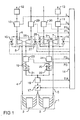
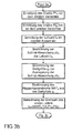
- FIG. 1 The structure of the bi-turbocharger arrangement illustrated in FIG. 1 will first be described below, in order subsequently to describe the method according to the invention with reference to the control-engineering equivalent circuit diagram shown in FIG. 2 and the flowchart shown in FIGS. 3a-3c.
- each of the two cylinder banks 2, 3 has a different number of cylinders.
- each of the two cylinder banks 2, 3 may have three cylinders, for example in the case of a six-cylinder engine.
- the internal combustion engine 1 has a separate exhaust tract 4, 5 for each of the two cylinder banks 2, 3, the exhaust tract 4 being connected to an exhaust gas turbine 6 of an exhaust gas turbocharger 8, while the exhaust gas tract 5 is connected to an exhaust gas turbine 7 of an exhaust gas turbocharger 9.
- a lambda probe 10, 11 and an exhaust gas catalyst 12, 13 are arranged, wherein the lambda probes 10, 11 the air ratio ⁇ 1 , ⁇ 2 in the exhaust tracts 4, 5 measure and to a control unit 14 forward.
- each have a bypass valve 15, 16 is arranged, which is controlled by the control unit 14 and a bypass of the exhaust gas turbines 6, 7 allows.
- the intake tracts of the two cylinder banks 2, 3 of the internal combustion engine 1 are first brought together, wherein the Fresh air supply to the internal combustion engine 1 is set by a throttle valve 17, which is controlled by the control unit 14.
- a temperature sensor 18 is arranged in the intake tract of the internal combustion engine 1, which measures the fresh air temperature and transmits a corresponding temperature signal TIA to the control unit 14.
- the fresh air tract of the internal combustion engine 1 branches upstream of the temperature sensor 18 in two branches 19, 20, wherein in the two branches 19, 20 each have a charge air cooler 21, 22 is arranged.
- the two pressure sensors 23, 24 measure the boost pressure P2 1 or P2 2 in the two branches 19, 20 and forward it to the control unit 14.
- a single pressure sensor is arranged, which is located in the area in which the intake tracts 19, 20 of the two cylinder banks 2, 3 are brought together.
- a bypass valve 27, 28 is arranged, wherein the two bypass valves 27, 28 are controlled by the control unit 14 and allow bypassing of the compressor 25, 26.
- the two bypass valves 27, 28 are mechanically controlled, for which purpose, for example, a spring can be used.
- a pressure sensor 29, 30 is arranged in each of the two branches 19, 20, wherein the two pressure sensors 29, 30 measure the pressure P1 1 , P1 2 upstream of the two compressors 25, 26.
- a subtracter 31 calculates the rotational speed deviation ⁇ 1 between a predetermined desired value ⁇ SOLL1 and the actual value ⁇ 1 measured by the lambda probe 10.
- the desired-actual deviation ⁇ 1 is then fed to a controller 32, which outputs a manipulated variable y 1 as a function of the desired-actual deviation ⁇ 1 and drives the internal combustion engine 1 with the manipulated variable y 1 to obtain the desired-actual deviation ⁇ 1 to correct.
- the manipulated variable y 1 is supplied to a computing unit 33 which calculates the exhaust gas mass flow MAF 1 from the manipulated variable y 1 .
- the arithmetic unit 33 is connected to a further arithmetic unit 34, which calculates the rotational speed n 1 of the exhaust gas turbocharger 8, wherein the arithmetic unit 34 downstream of the exhaust pressure mass flow MAF 1 , the pressure P1 1 upstream of the compressor 25, the pressure P2 1 behind a turbocharger speed model the compressor 25 and the temperature TIA measured by the temperature sensor 18 taken into account.
- a similar lambda control is provided for the cylinder bank 3 of the internal combustion engine 1, as can be seen from the control-engineering equivalent circuit diagram in Figure 2 in the lower area.
- the lambda control of the cylinder bank 3 is constructed in the same way as the lambda control for the cylinder bank 2, so that in the following a detailed description of the lambda control of the cylinder bank 3 is omitted and the following reference symbols are used for corresponding components, which are marked only for distinction by an apostrophe.
- the two arithmetic units 34, 34 ' are connected on the output side to a comparator unit 35, which calculates the rotational speed deviation ⁇ n from the two rotational speed values n 1 , n 2 .
- the temperature sensor 18 measures the temperature TIA in the intake tract of the internal combustion engine 1.
- the temperature TIA is required both for the calculation of the speed n 1 of the exhaust gas turbocharger 8 and for the calculation of the speed n 2 of the exhaust gas turbocharger 9 in the context of a turbocharger speed model, as will be described in detail.
- the pressure P1 1 upstream of the compressor 25 of the exhaust gas turbocharger 8 is measured by the pressure sensor 29.
- the pressure P2 1 downstream of the compressor 25 of the exhaust gas turbocharger 8 is measured by the pressure sensor 23.
- the two pressure values P1 1 and P2 1 are also required in the context of the turbocharger speed model to determine the speed n 1 of the exhaust gas turbocharger 8.
- the lambda probe 10 measures the air ratio ⁇ 1 in the exhaust gas tract 4 of the cylinder bank 2, in order then to calculate the desired-actual deviation ⁇ 1 .
- the manipulated variable y 1 is determined, which is generated by the controller 32 in the context of the control circuit equivalent circuit diagram shown in Figure 2 in order to correct the target-actual deviation ⁇ 1 .
- the computing unit 33 determines the exhaust mass flow rate MAF. 1
- the speed n 1 of the exhaust gas turbocharger 8 is then calculated from the exhaust gas mass flow MAF 1 , the temperature TIA and the pressure values P1 1 and P2 1 .
- the air ratio ⁇ 2 is measured, in order to calculate the target-actual deviation ⁇ 2 .
- the exhaust gas mass flow MAF 2 is then in turn calculated from the manipulated variable y 2 that is required to regulate the desired-actual deviation ⁇ 2 .
- the speed n 2 of the exhaust gas Turbocharger 9 calculated as part of a turbocharger speed model, the exhaust gas mass flow MAF 2 , the temperature TIA, and the pressure values P1 2 and P2 2 are taken into account.
- the speed difference ⁇ n is then calculated from the previously determined speed values n1, n2 and then compared with a predefined maximum value ⁇ n MAX .
- the boost pressure P2 1 or P2 2 is compared in each case with a predetermined maximum value P MAX in order to be able to detect an excessive increase in the boost pressure.
- the associated bypass valve 15 or 16 is at least partially opened in order to reduce the drive power of the exhaust gas turbocharger 8 or 9 and to prevent an excessive increase of the boost pressure P2 1 or P2 2 .
- a warning signal is set in such a case, indicating an excessive increase in the speed difference between the two exhaust gas turbochargers 8, 9 and can be evaluated by the control unit 14.
Landscapes
- Engineering & Computer Science (AREA)
- Chemical & Material Sciences (AREA)
- Combustion & Propulsion (AREA)
- Mechanical Engineering (AREA)
- General Engineering & Computer Science (AREA)
- Supercharger (AREA)
- Combined Controls Of Internal Combustion Engines (AREA)
Claims (13)
- Procédé pour le contrôle de régime d'un premier turbocompresseur à gaz d'échappement (8) pour un moteur à combustion interne (1), comprenant les étapes suivantes :a) détermination d'une première valeur de gaz d'échappement (λ1) exprimant la composition des gaz d'échappement du moteur à combustion interne (1) dans un premier conduit d'échappement (4),
caractérisé par
les étapes suivantes :b) définition d'une première valeur de régime (n1) exprimant la vitesse de rotation du premier turbocompresseur en fonction de la première valeur de gaz d'échappement (λ1) déterminée,c) régulation de la première valeur de gaz d'échappement (λ1) à une première valeur de consigne définie (λSOLL1) par une première grandeur de réglage (y1),d) détermination de la première grandeur de réglage (y1) exigée pour la régulation,e) définition de la première valeur de régime (n1) en fonction de la première grandeur de réglage (y1). - Procédé selon la revendication 1,
caractérisé en ce que
le moteur à combustion interne (1) comprend en plus du premier conduit d'échappement (4) un deuxième conduit d'échappement (5), et en plus du premier turbocompresseur à gaz d'échappement (8) un deuxième turbocompresseur à gaz d'échappement (9), les étapes suivantes étant exécutées en complément :a) détermination d'une deuxième valeur de gaz d'échappement (λ2) exprimant la composition des gaz d'échappement du moteur à combustion interne (1) dans le deuxième conduit d'échappement (5),b) définition d'une deuxième valeur de régime (n2) exprimant la vitesse de rotation du deuxième turbocompresseur (9) en fonction de la deuxième valeur de gaz d'échappement (λ2) déterminée,c) comparaison de la première valeur de régime (n1) avec la deuxième valeur de régime (n2) pour la détermination d'un écart de régime (Δn). - Procédé selon la revendication 2,
caractérisé par
les étapes suivantes :a) régulation de la deuxième valeur de gaz d'échappement (λ2) à une deuxième valeur de consigne définie (λSOLL2) par une deuxième grandeur de réglage (y2),b) détermination de la deuxième grandeur de réglage (y2) exigée pour la régulation,c) définition de la deuxième valeur de régime (n2) en fonction de la deuxième grandeur de réglage (y2). - Procédé selon l'une des revendications précédentes,
caractérisé en ce que
la première valeur de gaz d'échappement (λ1) et/ou la deuxième valeur de gaz d'échappement (λ2) expriment le facteur d'air du moteur à combustion interne (1). - Procédé selon l'une des revendications 2 à 4,
caractérisé en ce que
le débit massique de gaz d'échappement (MAF1, MAF2) et/ou le débit volumique de gaz d'échappement sont déduits de la première grandeur de réglage (y1) et/ou de la deuxième grandeur de réglage (y2). - Procédé selon l'une des revendications 2 à 5,
caractérisé en ce que
en fonction de la comparaison entre la première valeur de régime (n1) et la deuxième valeur de régime (n2), une soupape de dérivation (15, 16, 27, 28) est commandée pour réduire l'écart de régime (Δn) entre la première valeur de régime (n1) et la deuxième valeur de régime (n2). - Procédé selon la revendication 1,
caractérisé en ce que
la première valeur de gaz d'échappement (λ1) et/ou la deuxième valeur de gaz d'échappement (λ2) sont commandées sans rétro-couplage. - Dispositif pour le contrôle de régime d'un premier turbocompresseur à gaz d'échappement pour un moteur à combustion interne (1), comprenant :a) un premier capteur de gaz d'échappement (10) pour la mesure d'une première valeur de gaz d'échappement (λ1) exprimant la composition des gaz d'échappement du moteur à combustion interne (1) dans un premier conduit d'échappement (4),
caractérisé parb) une première unité d'analyse (14, 31-34) reliée au premier capteur de gaz d'échappement (10) pour la détermination d'une première valeur de régime (n1) exprimant la vitesse de rotation du premier turbocompresseur (8) en fonction de la première valeur de gaz d'échappement (λ1),c) un premier régulateur (32) pour la régulation de la première valeur de gaz d'échappement (λ1) dans le premier conduit d'échappement (4) à une première valeur de consigne définie (λSOLL1) par définition d'une première grandeur de réglage (y1),d) la première unité d'analyse (14, 31-34) étant reliée au premier régulateur (32),e) de telle manière que la première unité d'analyse (14, 31-34) définisse la première valeur de régime (n1) en fonction de la première grandeur de réglage (y1). - Dispositif selon la revendication 8,
caractérisé para) un deuxième capteur de gaz d'échappement (11) pour la mesure d'une deuxième valeur de gaz d'échappement (λ2) exprimant la composition des gaz d'échappement du moteur à combustion interne (1) dans un deuxième conduit d'échappement (5), etb) une deuxième unité d'analyse (14, 31'-34') pour la détermination d'une deuxième valeur de régime (n2) exprimant la vitesse de rotation d'un deuxième turbocompresseur (9) en fonction de la deuxième valeur de gaz d'échappement (λ2), etc) une unité de comparaison (35) pour la comparaison de la première valeur de régime (n1) avec la deuxième valeur de régime (n2) . - Dispositif selon la revendication 9,
caractérisé para) un deuxième régulateur (32') pour la régulation de la deuxième valeur de gaz d'échappement (λ2) dans le deuxième conduit d'échappement (5) à une deuxième valeur de consigne définie (λSOLL2) par définition d'une deuxième grandeur de réglage (y2),b) la deuxième unité d'analyse (31'-34') étant reliée au deuxième régulateur (32'), pour définir la deuxième valeur de régime (n2) en fonction de la deuxième grandeur de réglage (y2). - Dispositif selon l'une des revendications 8 à 10,
caractérisé en ce que
la première valeur de gaz d'échappement (λ1) et/ou la deuxième valeur de gaz d'échappement (λ2) expriment le facteur d'air du moteur à combustion interne (1). - Dispositif selon l'une des revendications 8 à 11,
caractérisé en ce que
le débit massique de gaz d'échappement (MAF1, MAF2) et/ou le débit volumique de gaz d'échappement sont déductibles de la première grandeur de réglage (y1) et/ou de la deuxième grandeur de réglage (y2). - Dispositif selon l'une des revendications 8 à 12,
caractérisé en ce que
pour réduire l'écart de régime entre le premier turbocompresseur (8) et le deuxième turbocompresseur (9), au moins une soupape de dérivation (15, 16, 27, 28) pouvant être commandée est prévue, l'unité de comparaison (35) étant reliée à la soupape de dérivation (15, 16, 27, 28).
Applications Claiming Priority (2)
| Application Number | Priority Date | Filing Date | Title |
|---|---|---|---|
| DE10320977A DE10320977A1 (de) | 2003-05-09 | 2003-05-09 | Verfahren zur Drehzahlüberwachung eines Bi-Turboladers |
| PCT/EP2004/050630 WO2004099585A1 (fr) | 2003-05-09 | 2004-04-28 | Procede pour controler le regime d'un bi-turbocompresseur |
Publications (2)
| Publication Number | Publication Date |
|---|---|
| EP1623103A1 EP1623103A1 (fr) | 2006-02-08 |
| EP1623103B1 true EP1623103B1 (fr) | 2007-12-05 |
Family
ID=33426727
Family Applications (1)
| Application Number | Title | Priority Date | Filing Date |
|---|---|---|---|
| EP04729896A Expired - Lifetime EP1623103B1 (fr) | 2003-05-09 | 2004-04-28 | Procede pour controler le regime d'un bi-turbocompresseur |
Country Status (4)
| Country | Link |
|---|---|
| US (1) | US7380401B2 (fr) |
| EP (1) | EP1623103B1 (fr) |
| DE (2) | DE10320977A1 (fr) |
| WO (1) | WO2004099585A1 (fr) |
Families Citing this family (20)
| Publication number | Priority date | Publication date | Assignee | Title |
|---|---|---|---|---|
| DE102004051837B4 (de) * | 2004-10-25 | 2006-11-09 | Siemens Ag | Verfahren und Vorrichtungen zum Steuern und zum Diagnostizieren eines Abgasturboladers |
| EP1809871B1 (fr) * | 2004-11-11 | 2012-01-11 | Honeywell International Inc. | Système de turbocompresseurs et procédés de commande pour commander un système de turbocompresseurs |
| US7640794B2 (en) * | 2007-09-06 | 2010-01-05 | Ford Global Technologies, Llc | Airflow balance for a twin turbocharged engine system |
| US8001782B2 (en) | 2007-09-26 | 2011-08-23 | Ford Global Technologies, Llc | Approach for identifying and responding to an unresponsive wastegate in a twin turbocharged engine |
| DE102009013040A1 (de) * | 2009-03-13 | 2010-09-16 | Volkswagen Ag | Brennkraftmaschine mit Registeraufladung |
| GB2472830B (en) * | 2009-08-20 | 2014-12-17 | Gm Global Tech Operations Inc | Twin turbo assembly and method for operating a twin turbo assembly |
| US8397499B2 (en) * | 2009-08-24 | 2013-03-19 | Ford Global Technologies, Llc | Methods and systems for turbocharger control |
| US8443602B2 (en) * | 2010-03-30 | 2013-05-21 | GM Global Technology Operations LLC | Closely-coupled exhaust aftertreatment device for a turbocharged internal combustion engine |
| DE102010036591B4 (de) * | 2010-07-23 | 2025-02-20 | Dr. Ing. H.C. F. Porsche Aktiengesellschaft | Kraftfahrzeug |
| DE102010055137A1 (de) * | 2010-12-18 | 2012-06-21 | Audi Ag | Verfahren zum Betreiben eines Kraftwagens mit zwei Turboladern |
| US9151229B2 (en) * | 2012-12-18 | 2015-10-06 | United Technologies Corporation | High pressure turbine speed calculation from fuel system hydraulic pressures |
| US9151217B2 (en) * | 2012-12-21 | 2015-10-06 | Ford Global Technologies, Llc | Twin turbocharger wastegate control |
| SE540370C2 (en) * | 2014-04-29 | 2018-08-21 | Scania Cv Ab | Förfarande samt system för styrning av ett överladdningssystem vid ett motorfordon |
| DE102014116636A1 (de) * | 2014-11-13 | 2016-05-19 | Dr. Ing. H.C. F. Porsche Aktiengesellschaft | Verfahren und Steuerungseinrichtung zum Betreiben einer Brennkraftmaschine |
| US11053875B2 (en) | 2016-02-10 | 2021-07-06 | Garrett Transportation I Inc. | System and method for estimating turbo speed of an engine |
| US9976474B2 (en) * | 2016-04-14 | 2018-05-22 | Caterpillar Inc. | Turbocharger speed anomaly detection |
| JP6848840B2 (ja) * | 2017-11-30 | 2021-03-24 | トヨタ自動車株式会社 | ウェイストゲートバルブの制御装置 |
| DE102018207829A1 (de) * | 2018-05-18 | 2019-12-05 | Bayerische Motoren Werke Aktiengesellschaft | Brennkraftmaschine |
| JP7230792B2 (ja) * | 2019-12-20 | 2023-03-01 | トヨタ自動車株式会社 | 内燃機関の制御装置 |
| US11615660B2 (en) * | 2020-11-17 | 2023-03-28 | Caterpillar Inc. | Identifying a failed turbocharger of a plurality of turbochargers |
Family Cites Families (9)
| Publication number | Priority date | Publication date | Assignee | Title |
|---|---|---|---|---|
| DE19615033A1 (de) * | 1996-04-17 | 1997-10-23 | Bosch Gmbh Robert | Anordnung zum Erkennen von Drehzahlabweichungen zwischen zwei Abgasturboladern |
| EP0894958B1 (fr) * | 1997-07-31 | 2005-02-09 | Dr.Ing.h.c. F. Porsche Aktiengesellschaft | Dispositif de détection de défaut pour un moteur à combustion interne et procédé d' actionnement d' un moteur à combustion interne |
| DE19743667B4 (de) * | 1997-10-02 | 2004-07-01 | Robert Bosch Gmbh | Anordnung zum Regeln des Ladedrucks einer Brennkraftmaschine |
| US6256992B1 (en) * | 1998-05-27 | 2001-07-10 | Cummins Engine Company, Inc. | System and method for controlling a turbocharger to maximize performance of an internal combustion engine |
| DE19832020C1 (de) * | 1998-07-16 | 1999-04-01 | Bosch Gmbh Robert | Verfahren und Vorrichtung zum Überwachen der Funktion zweier Abgasturbolader |
| DE19858293C1 (de) * | 1998-12-17 | 2000-03-09 | Daimler Chrysler Ag | Brennkraftmaschine mit einem Abgasturbolader mit variabler Turbinengeometrie |
| DE50110631D1 (de) * | 2000-07-07 | 2006-09-14 | Siemens Ag | Verfahren zur regelung eines ladedrucks in einer brennkraftmaschine mit einem abgasturbolader |
| JP2002276418A (ja) * | 2001-03-23 | 2002-09-25 | Hitachi Ltd | ターボ過給機付き筒内噴射エンジン及びその制御方法 |
| US6601388B1 (en) * | 2001-08-30 | 2003-08-05 | Caterpillar Inc | Turbocharger with enhanced compressor bleed capability |
-
2003
- 2003-05-09 DE DE10320977A patent/DE10320977A1/de not_active Ceased
-
2004
- 2004-04-28 US US10/555,969 patent/US7380401B2/en not_active Expired - Fee Related
- 2004-04-28 EP EP04729896A patent/EP1623103B1/fr not_active Expired - Lifetime
- 2004-04-28 WO PCT/EP2004/050630 patent/WO2004099585A1/fr not_active Ceased
- 2004-04-28 DE DE502004005655T patent/DE502004005655D1/de not_active Expired - Lifetime
Also Published As
| Publication number | Publication date |
|---|---|
| US7380401B2 (en) | 2008-06-03 |
| EP1623103A1 (fr) | 2006-02-08 |
| DE502004005655D1 (de) | 2008-01-17 |
| DE10320977A1 (de) | 2004-12-09 |
| US20060260306A1 (en) | 2006-11-23 |
| WO2004099585A1 (fr) | 2004-11-18 |
Similar Documents
| Publication | Publication Date | Title |
|---|---|---|
| EP1623103B1 (fr) | Procede pour controler le regime d'un bi-turbocompresseur | |
| DE10310221B4 (de) | Verfahren zur Begrenzung eines Ladedrucks | |
| EP1299628B1 (fr) | Procede permettant de reguler la pression d'admission dans un moteur thermique dote d'un turbocompresseur a gaz d'echappement | |
| EP0856097B1 (fr) | Systeme pour detecter des ecarts de regime entre deux turbocompresseurs | |
| DE102006016540B4 (de) | Verfahren und System zum Steuern eines Turbolader-Verdichterstoßes | |
| DE102015200906B4 (de) | Steuervorrichtung und Steuerverfahren für einen Verbrennungsmotor mit einem Auflader | |
| WO1999004150A1 (fr) | Procede et dispositif pour proteger un turbocompresseur | |
| DE102014217591A1 (de) | Verfahren und Vorrichtung zur Ansteuerung eines Abgasrückführventils einer aufgeladenen Brennkraftmaschine mit Abgasrückführung | |
| DE102015200155A1 (de) | Steuer-/Regeleinrichtung für einen Verbrennungsmotor | |
| DE102008043975B4 (de) | Verfahren und Vorrichtung zum Bereitstellen einer Luftmassenstromangabe bei einem aufgeladenen Verbrennungsmotor | |
| EP2466091A1 (fr) | Procédé de fonctionnement d'un véhicule automobile doté de deux turbosoufflantes | |
| EP1999352A1 (fr) | Procédé et dispositif conçus pour réguler ou commander un compresseur d'un turbocompresseur à gaz d'échappement | |
| DE102008044156A1 (de) | Verfahren und Vorrichtung zur Ladedruckregelung in einem Kraftfahrzeug | |
| DE19513156C1 (de) | Turboaufgeladene Brennkraftmaschine mit einer Fehlererkennung und Verfahren zum Betreiben einer turboaufgeladenen Brennkraftmaschine mit einer Fehlererkennung | |
| DE102011081949B4 (de) | Verfahren und Vorrichtung zur Durchführung einer Regelung, insbesondere zum Einsatz in einem Kraftfahrzeug | |
| DE102018131500A1 (de) | Verfahren zum Betreiben eines Kraftfahrzeugs | |
| DE60223881T2 (de) | Verfahren und Einrichtung zur Regelung des Luftstromes in einem Ansaugkrümmer einer Brennkraftmaschine eines Kraftfahrzeuges | |
| EP3662152B1 (fr) | Procédé servant à définir une pression de suralimentation de base d'un système d'acheminement de gaz d'un moteur à combustion interne et commande de moteur servant à mettre en oeuvre un procédé de ce type | |
| DE102012219516A1 (de) | Verfahren zum Erkennen einer Manipulation an einem Verbrennungsmotor | |
| EP2469061B1 (fr) | Procédé et dispositif de commande pour déterminer la charge en suies d'un filtre à particules | |
| DE3531744A1 (de) | Verfahren und vorrichtung zum steuern des aufladedrucks fuer einen turbolader | |
| DE3724302A1 (de) | Verfahren und vorrichtung zum regeln des ladedrucks bei einer mit einem turbolader versehenen brennkraftmaschine | |
| EP1609970B1 (fr) | Méthode et dispositif pour le fonctionnement d'un moteur à combustion interne | |
| DE10320978B3 (de) | Verfahren zur Drehzahlüberwachung eines Bi-Turboladers | |
| DE102009014533A1 (de) | Steuerungseinrichtung und Verfahren zum Steuern eines Turboladers bzw. einer mit dem Turbolader verbundenen Brennkraftmaschine |
Legal Events
| Date | Code | Title | Description |
|---|---|---|---|
| PUAI | Public reference made under article 153(3) epc to a published international application that has entered the european phase |
Free format text: ORIGINAL CODE: 0009012 |
|
| 17P | Request for examination filed |
Effective date: 20050831 |
|
| AK | Designated contracting states |
Kind code of ref document: A1 Designated state(s): DE FR GB |
|
| DAX | Request for extension of the european patent (deleted) | ||
| RBV | Designated contracting states (corrected) |
Designated state(s): DE FR GB |
|
| GRAP | Despatch of communication of intention to grant a patent |
Free format text: ORIGINAL CODE: EPIDOSNIGR1 |
|
| GRAS | Grant fee paid |
Free format text: ORIGINAL CODE: EPIDOSNIGR3 |
|
| GRAA | (expected) grant |
Free format text: ORIGINAL CODE: 0009210 |
|
| RAP1 | Party data changed (applicant data changed or rights of an application transferred) |
Owner name: SIEMENS VDO AUTOMOTIVE AG |
|
| AK | Designated contracting states |
Kind code of ref document: B1 Designated state(s): DE FR GB |
|
| REG | Reference to a national code |
Ref country code: GB Ref legal event code: FG4D Free format text: NOT ENGLISH |
|
| GBT | Gb: translation of ep patent filed (gb section 77(6)(a)/1977) | ||
| REF | Corresponds to: |
Ref document number: 502004005655 Country of ref document: DE Date of ref document: 20080117 Kind code of ref document: P |
|
| RAP2 | Party data changed (patent owner data changed or rights of a patent transferred) |
Owner name: VDO AUTOMOTIVE AG |
|
| ET | Fr: translation filed | ||
| RAP2 | Party data changed (patent owner data changed or rights of a patent transferred) |
Owner name: CONTINENTAL AUTOMOTIVE GMBH |
|
| PLBE | No opposition filed within time limit |
Free format text: ORIGINAL CODE: 0009261 |
|
| STAA | Information on the status of an ep patent application or granted ep patent |
Free format text: STATUS: NO OPPOSITION FILED WITHIN TIME LIMIT |
|
| 26N | No opposition filed |
Effective date: 20080908 |
|
| PGFP | Annual fee paid to national office [announced via postgrant information from national office to epo] |
Ref country code: FR Payment date: 20090414 Year of fee payment: 6 |
|
| PGFP | Annual fee paid to national office [announced via postgrant information from national office to epo] |
Ref country code: GB Payment date: 20090421 Year of fee payment: 6 |
|
| GBPC | Gb: european patent ceased through non-payment of renewal fee |
Effective date: 20100428 |
|
| REG | Reference to a national code |
Ref country code: FR Ref legal event code: ST Effective date: 20101230 |
|
| PG25 | Lapsed in a contracting state [announced via postgrant information from national office to epo] |
Ref country code: GB Free format text: LAPSE BECAUSE OF NON-PAYMENT OF DUE FEES Effective date: 20100428 |
|
| PG25 | Lapsed in a contracting state [announced via postgrant information from national office to epo] |
Ref country code: FR Free format text: LAPSE BECAUSE OF NON-PAYMENT OF DUE FEES Effective date: 20100430 |
|
| REG | Reference to a national code |
Ref country code: DE Ref legal event code: R084 Ref document number: 502004005655 Country of ref document: DE |
|
| REG | Reference to a national code |
Ref country code: DE Ref legal event code: R081 Ref document number: 502004005655 Country of ref document: DE Owner name: VITESCO TECHNOLOGIES GMBH, DE Free format text: FORMER OWNER: CONTINENTAL AUTOMOTIVE GMBH, 30165 HANNOVER, DE |
|
| PGFP | Annual fee paid to national office [announced via postgrant information from national office to epo] |
Ref country code: DE Payment date: 20200430 Year of fee payment: 17 |
|
| REG | Reference to a national code |
Ref country code: DE Ref legal event code: R119 Ref document number: 502004005655 Country of ref document: DE |
|
| REG | Reference to a national code |
Ref country code: DE Ref legal event code: R081 Ref document number: 502004005655 Country of ref document: DE Owner name: VITESCO TECHNOLOGIES GMBH, DE Free format text: FORMER OWNER: VITESCO TECHNOLOGIES GMBH, 30165 HANNOVER, DE |
|
| PG25 | Lapsed in a contracting state [announced via postgrant information from national office to epo] |
Ref country code: DE Free format text: LAPSE BECAUSE OF NON-PAYMENT OF DUE FEES Effective date: 20211103 |