EP1623366B1 - Fernsensor, einrichtung und verfahren zur aktivierung gewählter fernsensorkomponenten - Google Patents
Fernsensor, einrichtung und verfahren zur aktivierung gewählter fernsensorkomponenten Download PDFInfo
- Publication number
- EP1623366B1 EP1623366B1 EP04732129A EP04732129A EP1623366B1 EP 1623366 B1 EP1623366 B1 EP 1623366B1 EP 04732129 A EP04732129 A EP 04732129A EP 04732129 A EP04732129 A EP 04732129A EP 1623366 B1 EP1623366 B1 EP 1623366B1
- Authority
- EP
- European Patent Office
- Prior art keywords
- reader
- radio
- remote
- identifier
- signal
- Prior art date
- Legal status (The legal status is an assumption and is not a legal conclusion. Google has not performed a legal analysis and makes no representation as to the accuracy of the status listed.)
- Expired - Lifetime
Links
Images

Classifications
-
- G—PHYSICS
- G06—COMPUTING OR CALCULATING; COUNTING
- G06K—GRAPHICAL DATA READING; PRESENTATION OF DATA; RECORD CARRIERS; HANDLING RECORD CARRIERS
- G06K7/00—Methods or arrangements for sensing record carriers, e.g. for reading patterns
- G06K7/10—Methods or arrangements for sensing record carriers, e.g. for reading patterns by electromagnetic radiation, e.g. optical sensing; by corpuscular radiation
- G06K7/10009—Methods or arrangements for sensing record carriers, e.g. for reading patterns by electromagnetic radiation, e.g. optical sensing; by corpuscular radiation sensing by radiation using wavelengths larger than 0.1 mm, e.g. radio-waves or microwaves
- G06K7/10019—Methods or arrangements for sensing record carriers, e.g. for reading patterns by electromagnetic radiation, e.g. optical sensing; by corpuscular radiation sensing by radiation using wavelengths larger than 0.1 mm, e.g. radio-waves or microwaves resolving collision on the communication channels between simultaneously or concurrently interrogated record carriers.
- G06K7/10079—Methods or arrangements for sensing record carriers, e.g. for reading patterns by electromagnetic radiation, e.g. optical sensing; by corpuscular radiation sensing by radiation using wavelengths larger than 0.1 mm, e.g. radio-waves or microwaves resolving collision on the communication channels between simultaneously or concurrently interrogated record carriers. the collision being resolved in the spatial domain, e.g. temporary shields for blindfolding the interrogator in specific directions
-
- G—PHYSICS
- G06—COMPUTING OR CALCULATING; COUNTING
- G06K—GRAPHICAL DATA READING; PRESENTATION OF DATA; RECORD CARRIERS; HANDLING RECORD CARRIERS
- G06K19/00—Record carriers for use with machines and with at least a part designed to carry digital markings
- G06K19/06—Record carriers for use with machines and with at least a part designed to carry digital markings characterised by the kind of the digital marking, e.g. shape, nature, code
- G06K19/067—Record carriers with conductive marks, printed circuits or semiconductor circuit elements, e.g. credit or identity cards also with resonating or responding marks without active components
- G06K19/07—Record carriers with conductive marks, printed circuits or semiconductor circuit elements, e.g. credit or identity cards also with resonating or responding marks without active components with integrated circuit chips
- G06K19/0723—Record carriers with conductive marks, printed circuits or semiconductor circuit elements, e.g. credit or identity cards also with resonating or responding marks without active components with integrated circuit chips the record carrier comprising an arrangement for non-contact communication, e.g. wireless communication circuits on transponder cards, non-contact smart cards or RFIDs
-
- G—PHYSICS
- G06—COMPUTING OR CALCULATING; COUNTING
- G06K—GRAPHICAL DATA READING; PRESENTATION OF DATA; RECORD CARRIERS; HANDLING RECORD CARRIERS
- G06K19/00—Record carriers for use with machines and with at least a part designed to carry digital markings
- G06K19/06—Record carriers for use with machines and with at least a part designed to carry digital markings characterised by the kind of the digital marking, e.g. shape, nature, code
- G06K19/067—Record carriers with conductive marks, printed circuits or semiconductor circuit elements, e.g. credit or identity cards also with resonating or responding marks without active components
- G06K19/07—Record carriers with conductive marks, printed circuits or semiconductor circuit elements, e.g. credit or identity cards also with resonating or responding marks without active components with integrated circuit chips
- G06K19/073—Special arrangements for circuits, e.g. for protecting identification code in memory
- G06K19/07309—Means for preventing undesired reading or writing from or onto record carriers
- G06K19/07345—Means for preventing undesired reading or writing from or onto record carriers by activating or deactivating at least a part of the circuit on the record carrier, e.g. ON/OFF switches
Definitions
- the present invention relates to a remote identifier according to Claim 1.
- the invention also relates to an apparatus and method for activating desired remote-identifier components.
- a remote identifier is a tag that is read remotely using a radio signal, and which includes an antenna, a voltage-generation circuit, rf-signal modulation/demodulation circuits, and a memory. The memory can be both written and read with the aid of the radio signal.
- remote identifiers There are several types of remote identifiers: passive and active, as well as those that can be connected inductively, capacitively, or with the aid of a radio-frequency radiation field. Passive remote identifiers generate the electrical energy they need from the rf-field aimed at them. Active identifiers contain a separate battery. Inductively-connected remote identifiers typically operate at frequencies of 125 kHz or 13.56 MHz.
- This invention concerns a passive remote identifier read using a radio-frequency radiation field.
- the 868 - 870 MHz band and the 2.4 - 2.4835 GHz ISM (Industrial Scientific Medical) band have been reserved for this operation.
- Remote sensors can be considered to be a sub-set of remote identifiers.
- a remote sensor has essentially the same operating principle as a remote identifier.
- circuits for converting a quantity (e.g., pressure, temperature) into a transmittable form In place of, or in addition to the memory, there are circuits for converting a quantity (e.g., pressure, temperature) into a transmittable form.
- Remote sensors have the advantage that wireless reading eliminates the need for cables. The cable and its installation usually form a considerably larger cost item than the sensor itself.
- the reader can be made small enough to be held in the hand.
- the reader can also be integrated as part of a mobile telephone. Though the reader is small, the reading distance can be several metres.
- a user wants data concerning a product they see, the following problem arises - they must read the data of all of the products that are nearby, then use a menu to select the correct product from a set of several products.
- the wavelength of a microwave is typically longer than the size of the reader, which means that the microwaves can only be partly aimed.
- the user can defined the product sufficiently precisely for only the data on the desired product to be transmitted to the device.
- the differences between products are often so small (different sizes of shoe) that the selection is laborious, while in addition the user does not have the code for searching for a specific product.
- a mobile telephone is made to be able to control all kinds of devices, to read different kinds of goods, most of the memory of the mobile telephone will be used for storing this information.
- Another example is controlling a device (e.g., a television). If we want to control nearby devices, according to existing technology we select a suitable operating device from a menu and control it.
- the situation can also be arranged so that all devices nearby automatically hand over the ability to control them to a mobile telephone.
- Both of the aforementioned solutions are clumsy.
- the invention is intended to create an entirely new type of remote identifier and an apparatus and method for activating desired remote-identifier components, with the aid of which the problems of the prior art described above can be solved.
- the invention is based on using a reader to actively select a remote-identifier component, either by bringing the reader sufficiently close to the remote identifier, or by pointing to the remote-identifier component over another transmission path, an optical signal.
- the remote identifier or sensor is targeted using a different frequency to the reading frequency, using infrared or visible light.
- the second frequency is synchronized with the reading frequency.
- the sensor according to the invention is equipped with means for indicating this second frequency.
- this means can be an element with a conductivity that changes due to the effect of light.
- the remote identifier according to the invention is characterized by what is stated in Claim 1.
- a desired remote identifier and its related product can be selected in a situation, in which several remote identifiers are within the range of the reader. Such a situation can arise, for example, in a shop, in which nearly all the products are equipped with a remote identifier.
- the invention also permits a new user interface to be transferred to a reader, such as a mobile station.
- a reader such as a mobile station.
- the mobile station can be converted, for example, into a remote control for a TV, DVD, or other remotely controlled device.
- One preferred embodiment of the invention permits product data to be read using a contact method.
- the synchronization of the two different signals in the activation event allows a remote identifier according to the invention to be manufactured at very low cost.
- the photosensitive identifier element can be made from a cheap and unstable material.
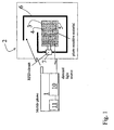
- Figure 1 shows schematically the remote identifier according to the invention and its reader.
- Figure 2 shows the behaviour of the signals according to the invention on a time axis.
- the reader according to the invention can be an entirely independent unit, which is intended only for reading remote identifiers. However, such a reader is typically integrated in connection with some second device.
- a very natural and technically suitable device for implementing the functions of a reader is a mobile station, typically a mobile telephone. Mobile stations include an antenna, a radio-frequency component, a microprocessor, a memory, and a battery acting as a power supply, making it an easy and cost-effective task to integrate a reader in such a unit.
- the combination of a reader with a mobile station is disclosed in, for instance, PCT application FI02/00818 .
- the user interface operates by the user either touching or pointing to the product in one way or another, so that in this way only this product's data is transferred to the reader, or the device in question activates and transfers the ability to control it to the mobile station.
- Products or goods that the user 'touches' with the device can be called TouchMe products.
- PointMe products If the product is far away and the user does not want to, or cannot touch the product, they can point to the product using a laser or lamp in the reader. Such products can be termed PointMe products.
- This invention discloses the technical solutions required to implement both the touching (TouchMe) and pointing (PointMe) concepts.
- Figure 1 shows in general the manner, in which a mobile station 1 activates a remote identifier 2, with the aid of a photosensitive material 3 added to the antenna laminate.
- Two conductive electrodes 4 and 5, the resistance between which is measured by current-measurement using an RFID circuit 7, are located inside the photosensitive material.
- An antenna 6, with the aid of which the remote identifier communicates with the reader, in this case the mobile station, is also connected to the RFID circuit 7.
- the mobile station includes a light source 10, which can be a semiconductor laser in the visible-light or infrared range. Alternatively, the light source can be a normal incandescent-wire lamp, with suitable focussing optics.
- the light source should be able to form a beam narrow enough for only a single remote identifier 1 to be selected for reading.
- a suitable beam width (diameter) for the light is 10 - 50 cm at a distance of five metres from the reader. However, the suitable beam width will always vary according to the target.
- the light source is controlled using a control circuit 11, which pulses the light at the same frequency as the radio-frequency signal.
- the modulation of the light source can be implemented using an electrically controlled switch, the modulation being textbook information and will not be described in greater detail in this connection.
- the user presses a button in the mobile station 1, which activates reading.
- the device adjusts the reading power to be so low that only a sticker that is very close will be activated.
- the power is increased until one, and only one sticker is activated.
- the maximum power is limited, so that reading will only succeed if the sticker is at an agreed distance (e.g., 5 cm) from the reader. By this procedure, it is highly probable that the device will read only one sticker that is even closer.
- the correct sticker can be selected on the basis of the strength of the reflected signal.
- touch reading When using UHF and microwaves, touch reading (TouchMe) often takes place at a distance that is shorter than the wavelength.
- connection to the product is formed using either a magnetic field or an electrical field.
- the antenna of the reader and correspondingly the antenna of the sticker should therefore be designed to be compatible with each other.
- the remote identifier 2 will become sensitive to visible light, or infrared radiation.
- One preferred way of adding photosensitivity to the remote identifier 2 is to surface the antenna entirely or partly with an electrically conductive polymer, which can be manufactured to be semiconducting.
- an electrically conductive polymer which can be manufactured to be semiconducting.
- the photosensitivity can be located in either an integrated circuit, or in the antenna laminate.
- the signal is so weak and the power of the remote identifier so small that it is very difficult to use only a single value to express the light.
- ambient light levels vary continuously and the sensitivity of a cheap photoelectric detector depends on both the time and the lighting.
- the amplitude modulation of the radio signal, or the pulse-width modulation of the pulse, sent by the mobile station can be synchronized with the amplitude modulation of the light.
- a simple solution is created by modulating the amplitude of a microwave or a radio-frequency signal, using the same frequency as in the modulation of the intensity of the light source.
- Another simple method is to modulate the remote-identifier circuit electrically using a frequency f and the light using the frequency f/2.
- the frequency f is divided by two and is correlated against the light signal (f/2).
- the use of different frequencies helps to symmetrize the signal and to eliminate crosstalk.
- the remote-identifier circuit 1 receives very highly correlated signals over two routes, we can considerably improve the ability of the remote-identifier 1 to distinguish the desired light signal from other signals.
- Figure 2 shows one simple method for combining a light signal and an RF signal.
- the explanations of the waveforms are shown at the right-hand end of each curve.
- the curves have a common horizontal time axis.
- a microwave signal is modulated using pulse-width modulation at a frequency f and a symmetrical square-wave at a frequency f/2 is made by division from this signal.
- the light is modulated at the frequency f/2, which leads to the modulation, at the frequency f/2, of the value of the resistance 3 in the laminate. In the figure, this is shown by the curve depicting the conductivity of the photoelectric detector 3.
- the conductivity signal is obtained from measuring the current between the electrodes 4 and 5.
- the electrically produced symmetrical signal at the frequency f/2 is fed as voltage between the electrodes 4 and 5.
- the current is thus determined from the conductivity of the resistance 3, which, in turn, depends on the external lighting. If the value of the resistance does not correlate at the frequency f/2 the current flowing through the resistance averages zero. If, however, the resistance value varies at the frequency f/2 and is phase-synchronized with the electrically produced signal, a direct-current component appears in the current and is detected by the comparator after the filter (the lowest curve in Figure 2 ).
- This voltage signal which is proportional to the current, is integrated for a predefined time, typically a few tens - hundred of milliseconds and, if a predefined voltage limit (the broken line in the figure) is reached, two-way communications are activated between the remote identifier 2 and the reader 1.
- the electrical signal is compared in the remote identifier with the light signal, or with some other independent signal coming from the reader and, if a correlation is detected between these two signals, the remote identifier 2 begins to communicate with the reader 1.
- TV television
- DVD digital versatile disc
- the simple form of detection described above can be replaced with a more advanced and expensive circuit, utilizing, for example, the infrared receivers of remote-controlled devices.
- the essential feature is that the synchronization of the radio path and the optical link permits the optical signal to be detected using a very low measurement power.
- Both the touching (TouchMe) and pointing (PointMe) concepts can be applied to obtain data from the desired product. For example, when looking for new shoes, one can first of all touch one's own shoes, when the size of shoe and other data will be transferred to the mobile station. This information can be used when buying new shoes.
- the light source can also be pointed at a light, when a sticker will tell the mobile station that the light can be controlled, for example, using Bluetooth and the remote identifier activates communications immediately, the light comes on, and possibly the mobile station can be used to adjust the light's brightness. If a light or TV can be controlled using infrared, the remote identifier will also tell this and automatically active the function in the mobile station required for control.
- the mobile station By using the touching (TouchMe) concept embedded in the mobile station, or on the other hand the pointing (PointMe) concept connected to the remote identifier and a remote-identifier reader in the mobile station, the mobile station will very economically be turned into a device, which can be used to collect information on desired products, or to control the environment, by either pointing to products or devices, or by touching them. For example, if we touch another person's business card that is equipped with a remote identifier with a mobile station, the information on the person's business card will be automatically transferred to the mobile station.
- the data can be taken from the identifier as such, or else the identifier will activate Bluetooth in the reading mobile station, which will, in turn, read the necessary data from the mobile telephone of the person owning the business card, without anyone pressing the keys of the mobile telephone. By touching the service manual of a car, the mobile station will automatically contact the nearest service facility.
- Corresponding examples can be invented endlessly.
- the essential feature is that, by adding the said properties to both the reader and the remote identifier, the invention can be used to offer consumers a 'physical' interface with the environment, through a personal handheld device. This permits an interface that is concrete and very natural to people, and which can be tailored separately for each consumer.
- Both the pointing and the touching methods are also highly suitable for use in connection with remote sensor technology.
- readings can be obtained from a remotely read temperature sensor, without disturbing other sensors.
- this makes it possible to obtain a reading from a sensor in a wine bottle, either by pointing to the sensor, or by bringing the reader (e.g., a mobile telephone) close to the sensor.
Landscapes
- Engineering & Computer Science (AREA)
- Physics & Mathematics (AREA)
- General Physics & Mathematics (AREA)
- Computer Hardware Design (AREA)
- Theoretical Computer Science (AREA)
- Computer Networks & Wireless Communication (AREA)
- Health & Medical Sciences (AREA)
- Toxicology (AREA)
- Microelectronics & Electronic Packaging (AREA)
- Electromagnetism (AREA)
- Computer Vision & Pattern Recognition (AREA)
- Artificial Intelligence (AREA)
- General Health & Medical Sciences (AREA)
- Computer Security & Cryptography (AREA)
- General Engineering & Computer Science (AREA)
- Selective Calling Equipment (AREA)
- Burglar Alarm Systems (AREA)
- Near-Field Transmission Systems (AREA)
- Geophysics And Detection Of Objects (AREA)
- Measuring Fluid Pressure (AREA)
- Optical Communication System (AREA)
- Details Of Television Systems (AREA)
Claims (7)
- Fernkennung (2), welche an Produkten befestigt werden kann, wobei die Kennung umfasst:- einen Mikroschaltkreis (7), welcher einen Speicher und eine Einrichtung zum Verarbeiten eines Funkfrequenzsignals umfasst,- eine mit dem Mikroschaltkreis (7) verbundene Antenne (6), mittels welcher sowohl das Signal als auch elektrische Energie für die Betriebsspannung des Mikroschaltkreises (7) empfangen werden können,wobei die Kennung weiterhin dadurch gekennzeichnet ist, dass- eine Komponente (3), deren elektrische Eigenschaften sich aufgrund des Effekts einer Bestrahlung durch ein Signal aus infrarotem oder sichtbarem Licht verändern, elektrisch mit dem Mikroschaltkreis (7) der Fernkennung verbunden ist, und- eine Einrichtung in dem Mikroschaltkreis (7) bereitgestellt ist zum Aktivieren der Fernkennung (2) für eine wechselseitige Datenübertragung, wobei die Einrichtung den kombinierten Effekt einer Veränderung des Funkfrequenzsignals und einer Veränderung in den elektrischen Eigenschaften der Komponente (3) korreliert.
- Fernkennung (2) nach Anspruch 1, dadurch gekennzeichnet, dass die Komponente (3), welche sich elektrisch aufgrund von Bestrahlung verändert, ein photosensitiver Polymerwiderstand ist.
- Lesegerät zum Lesen einer Fernkennung (2), wobei das Lesegerät umfasst:- ein Einrichtung zum Übertragen und Empfangen eines Funkfrequenzsignals zu und von der Fernkennung (2),wobei das Lesegerät weiterhin dadurch gekennzeichnet ist, dass- das Lesegerät (1) eine Lichtquelle (10) umfasst, welche ein Signal ausstrahlt, sowie- eine Steuereinrichtung (11) für die Lichtquelle (10), welche das Signal der Lichtquelle mit dem Funkfrequenzsignal synchronisiert.
- Lesegerät (1) nach Anspruch 3, dadurch gekennzeichnet, dass es in eine Mobilstation (1) integriert ist.
- Verfahren in einem Lesegerät (1) von Fernkennungen, wobei das Lesegerät Information zu der Fernkennung (2) nach Anspruch 1 sendet und Information von der Fernkennung (2) empfangen wird, dadurch gekennzeichnet, dass das Signal in dem infraroten oder sichtbaren Lichtbereich mit dem Funkfrequenzsignal synchronisiert wird und gleichzeitig zusammen mit dem Funkfrequenzsignal zu der Fernkennung gesendet wird.
- Fernkennungssystem, welches umfasst- ein Lesegerät (1), umfassend eine Einrichtung zum Bereitstellen einer Übertragung und eines Empfangs eines Funkfrequenzsignals,- eine Fernkennung (2), umfassend eine Einrichtung zum Bereitstellen einer wechselseitigen Funkfrequenzkommunikation mit dem Lesegerät (1) und eine Einrichtung zum Verwerten der vom dem Lesegerät ausgestrahlten Energie als eigene Betriebsspannung,wobei das System weiterhin dadurch gekennzeichnet ist, dass- das Lesegerät (1) eine Lichtquelle (10) umfasst, welche ein Signal ausstrahlt und im infraroten oder sichtbaren Lichtbereich operiert, und eine Steuereinrichtung (11) umfasst zum Synchronisieren des Signals der Lichtquelle mit dem Funkfrequenzsignal; und- die Fernkennung (2) eine Einrichtung (3) umfasst zum Detektieren der gleichzeitigen Anwesenheit des Signals der Lichtquelle und des Funkfrequenzsignals durch Korrelieren der beiden Signale.
- Fernkennungsverfahren, in welchem- Funkfrequenzinformation und elektrische Energie mit Hilfe eines Lesegeräts (1) an eine Fernkennung gesendet werden,- die Fernkennung (2) verwendet wird, um Funkfrequenzinformation unter Verwendung eines Funkfrequenzsignals als Betriebsenergie zu empfangen und zu übertragen,wobei das Verfahren weiterhin dadurch gekennzeichnet ist, dass- ein Lesegerät (1) verwendet wird, ein Lichtsignal im infraroten oder sichtbaren Lichtbereich synchron mit einem Funkfrequenzsignal zu übertragen, und- die Fernkennung (2) verwendet wird, die gleichzeitige Anwesenheit des Lichtsignals und des Funkfrequenzsignals durch Korrelieren der beiden Signale zu detektieren.
Applications Claiming Priority (2)
| Application Number | Priority Date | Filing Date | Title |
|---|---|---|---|
| FI20030706A FI117358B (fi) | 2003-05-12 | 2003-05-12 | Etätunnistin, laitteisto ja menetelmä haluttujen etätunnistinkomponenttien aktivoimiseksi |
| PCT/FI2004/000281 WO2004100058A1 (en) | 2003-05-12 | 2004-05-11 | Remote sensor, device and method for activating selected remote sensor components |
Publications (2)
| Publication Number | Publication Date |
|---|---|
| EP1623366A1 EP1623366A1 (de) | 2006-02-08 |
| EP1623366B1 true EP1623366B1 (de) | 2009-06-17 |
Family
ID=8566094
Family Applications (1)
| Application Number | Title | Priority Date | Filing Date |
|---|---|---|---|
| EP04732129A Expired - Lifetime EP1623366B1 (de) | 2003-05-12 | 2004-05-11 | Fernsensor, einrichtung und verfahren zur aktivierung gewählter fernsensorkomponenten |
Country Status (8)
| Country | Link |
|---|---|
| US (1) | US7671721B2 (de) |
| EP (1) | EP1623366B1 (de) |
| JP (1) | JP4688788B2 (de) |
| AT (1) | ATE434235T1 (de) |
| CA (1) | CA2525110C (de) |
| DE (1) | DE602004021586D1 (de) |
| FI (1) | FI117358B (de) |
| WO (1) | WO2004100058A1 (de) |
Families Citing this family (16)
| Publication number | Priority date | Publication date | Assignee | Title |
|---|---|---|---|---|
| BRPI0518880A2 (pt) * | 2004-12-10 | 2008-12-16 | Koninkl Philips Electronics Nv | portador de dados com um chip, e, mÉtodo de comunicar com chips integrados em portadores de dados |
| CA2658556A1 (en) * | 2005-07-25 | 2007-02-01 | Kimberly Ann Mcrae | Intuitive based control elements, and interfaces and devices using said intuitive based control elements |
| JP2007102712A (ja) * | 2005-10-07 | 2007-04-19 | Nippon Signal Co Ltd:The | 非接触情報記録媒体、リーダライタ及び物品管理システム |
| DE102005062828A1 (de) * | 2005-12-27 | 2007-06-28 | Bundesdruckerei Gmbh | Dokument mit einem elektronischen Gerät, Vorrichtung zum Zugriff auf einen Datenspeicher und Computerprogrammprodukt |
| DE102006015782B4 (de) * | 2006-04-04 | 2021-09-16 | Infineon Technologies Ag | Vorrichtung zur Speicherung und drahtlosen Übertragung von Daten |
| US20080030305A1 (en) * | 2006-05-16 | 2008-02-07 | O'connor Ruaidhri M | Systems and Methods for Using a Tag |
| US20080034095A1 (en) * | 2006-08-01 | 2008-02-07 | Motorola, Inc. | Multi-representation media event handoff |
| DE102006040723A1 (de) * | 2006-08-31 | 2008-04-30 | Siemens Ag | RFID-Transponder mit Sensorelementen |
| US8760295B2 (en) * | 2008-12-19 | 2014-06-24 | Avery Dennison Corporation | Apparatus and methods for treating a wound |
| US9135547B2 (en) * | 2008-12-19 | 2015-09-15 | Avery Dennison Corporation | Optical control of RFID chips |
| US8205800B2 (en) * | 2009-10-20 | 2012-06-26 | Hand Held Products, Inc. | Long range selective RFID using laser photodetection wakeup |
| FI20096076A0 (fi) * | 2009-10-20 | 2009-10-20 | Valtion Teknillinen | Menetelmä ja järjestelmä kohteen paikallistamiseksi |
| WO2016024037A1 (en) * | 2014-08-13 | 2016-02-18 | Nokia Technologies Oy | Physical unclonable function |
| US9460321B1 (en) * | 2014-08-20 | 2016-10-04 | Sandia Corporation | Zero-power receiver |
| US10235614B1 (en) * | 2016-11-01 | 2019-03-19 | National Technology & Engineering Solutions Of Sandia, Llc | Communication device and method of making the same |
| EP3333776B1 (de) * | 2016-12-07 | 2021-01-27 | Porta Saber Lda | Aktivierung von rfid-transpondern mit licht |
Family Cites Families (20)
| Publication number | Priority date | Publication date | Assignee | Title |
|---|---|---|---|---|
| US4931789A (en) * | 1983-11-01 | 1990-06-05 | Universal Photonix, Inc. | Apparatus and method for a universal electronic locking system |
| JPH02226392A (ja) * | 1989-02-27 | 1990-09-07 | Omron Tateisi Electron Co | カード識別装置 |
| US5825045A (en) | 1992-02-13 | 1998-10-20 | Norand Corporation | Extended range highly selective low power consuming data tag and information display system |
| JPH05307428A (ja) * | 1992-04-28 | 1993-11-19 | Mitsubishi Electric Corp | リセット方式 |
| US5300875A (en) * | 1992-06-08 | 1994-04-05 | Micron Technology, Inc. | Passive (non-contact) recharging of secondary battery cell(s) powering RFID transponder tags |
| US6097301A (en) * | 1996-04-04 | 2000-08-01 | Micron Communications, Inc. | RF identification system with restricted range |
| US20050040961A1 (en) * | 1995-04-11 | 2005-02-24 | Tuttle John R. | RF identification system with restricted range |
| JPH09138276A (ja) * | 1995-11-14 | 1997-05-27 | Yokogawa Electric Corp | 無線データ収集装置 |
| AU6259098A (en) * | 1997-01-31 | 1998-08-25 | Thomson Consumer Electronics, Inc | Communications system for remote control systems |
| US6002344A (en) * | 1997-11-21 | 1999-12-14 | Bandy; William R. | System and method for electronic inventory |
| WO2001017138A1 (en) * | 1999-08-30 | 2001-03-08 | Mitsubishi Denki Kabushiki Kaisha | Wireless communication system |
| US6542083B1 (en) * | 1999-11-23 | 2003-04-01 | Xerox Corporation | Electronic tag position detection using radio broadcast |
| US6335685B1 (en) * | 2000-03-09 | 2002-01-01 | International Business Machines Corporation | Apparatus and method for locating containers and contents of containers using radio frequency tags |
| JP2001256452A (ja) * | 2000-03-09 | 2001-09-21 | Yozan Inc | タグic |
| US6975228B2 (en) * | 2000-04-17 | 2005-12-13 | Tc (Bermuda) License, Ltd. | Dual mode RFID device |
| JP2003021679A (ja) | 2001-07-06 | 2003-01-24 | Hitachi Kiden Kogyo Ltd | 入退場者の管理システム |
| FI20012051A7 (fi) | 2001-10-23 | 2003-04-24 | Valtion Teknillinen Tutkimuskeskus | Etätunnistin- tai anturijärjestelmä, sekä matkaviestin |
| US7002474B2 (en) * | 2002-07-17 | 2006-02-21 | Ncr Corporation | Radio frequency identification (RFID) tag and a method of operating an RFID tag |
| US7229023B2 (en) * | 2003-08-19 | 2007-06-12 | Mitsubishi Electric Research Laboratories, Inc. | Radio and optical identification tags |
| US7652557B2 (en) * | 2004-02-13 | 2010-01-26 | Kantrowitz Allen B | Optical transponder containing identification tag |
-
2003
- 2003-05-12 FI FI20030706A patent/FI117358B/fi not_active IP Right Cessation
-
2004
- 2004-05-11 CA CA2525110A patent/CA2525110C/en not_active Expired - Fee Related
- 2004-05-11 EP EP04732129A patent/EP1623366B1/de not_active Expired - Lifetime
- 2004-05-11 DE DE602004021586T patent/DE602004021586D1/de not_active Expired - Lifetime
- 2004-05-11 AT AT04732129T patent/ATE434235T1/de not_active IP Right Cessation
- 2004-05-11 JP JP2006505649A patent/JP4688788B2/ja not_active Expired - Fee Related
- 2004-05-11 WO PCT/FI2004/000281 patent/WO2004100058A1/en not_active Ceased
- 2004-05-11 US US10/555,014 patent/US7671721B2/en active Active
Also Published As
| Publication number | Publication date |
|---|---|
| ATE434235T1 (de) | 2009-07-15 |
| JP2007527037A (ja) | 2007-09-20 |
| JP4688788B2 (ja) | 2011-05-25 |
| FI117358B (fi) | 2006-09-15 |
| FI20030706A0 (fi) | 2003-05-12 |
| CA2525110C (en) | 2012-08-28 |
| DE602004021586D1 (de) | 2009-07-30 |
| US7671721B2 (en) | 2010-03-02 |
| WO2004100058A1 (en) | 2004-11-18 |
| FI20030706L (fi) | 2004-11-13 |
| EP1623366A1 (de) | 2006-02-08 |
| CA2525110A1 (en) | 2004-11-18 |
| US20060202802A1 (en) | 2006-09-14 |
Similar Documents
| Publication | Publication Date | Title |
|---|---|---|
| US7671721B2 (en) | Remote sensor, device and method for activating selected remote sensor components | |
| US7400250B2 (en) | Indicating radio frequency identification (RF-ID) tag | |
| EP2084821B1 (de) | Aktivierung von nahfeldkommunikation (nfk) | |
| US8446256B2 (en) | Multiplexing radio frequency signals | |
| EP1527409B1 (de) | Leserschnittstelleneinrichtung | |
| US20100231382A1 (en) | Wireless temperature sensor network | |
| KR101726420B1 (ko) | 비컨을 이용한 결제장치 및 방법 | |
| EP3545469B1 (de) | Verfahren und vorrichtung zur passiven fernsteuerung | |
| US20110090060A1 (en) | Isolating RFID Reader | |
| CA2532875A1 (en) | System and method for optimizing power usage in a radio frequency communication device | |
| US20040195324A1 (en) | Non-contact IC card reader/writer device, non-contact IC card, input device, and method of calculating location of non-contact IC card | |
| US20080186178A1 (en) | RFIDS, interrogators, indication systems, methods of determining a bi-directional communication range of an interrogator, methods of activating an observable indicator, and methods of indicating bi-directional functionality of a radio connection | |
| KR20110110987A (ko) | 무선 전력 전송 제어 방법 및 장치 | |
| US9204485B2 (en) | Network node for a wireless sensor network | |
| JP2000049653A (ja) | 非接触通信システム | |
| US20110285534A1 (en) | Remote control apparatus using rfid and method thereof | |
| EP3701633A1 (de) | Fernüberwachung der datenkommunikation zwischen einer rfid-vorrichtung und einem lesersystem | |
| KR102250248B1 (ko) | Uwb를 이용한 무선 충전 시스템 | |
| JP2019175057A (ja) | 通信装置及び環境変化の検知方法 | |
| US8653943B2 (en) | Radio frequency identification system provided for access control | |
| US20140241714A1 (en) | Protocol system and related method of automatically switching connection | |
| US8260342B2 (en) | Communications systems management using MM-wave based motion sensing | |
| KR101870838B1 (ko) | 모바일 기기의 수광 센서를 활용한 가시광 rfid 시스템 | |
| KR102200470B1 (ko) | 액정 기반의 무선주파수 수신장치 | |
| KR100836469B1 (ko) | Rfid 리더 및 rfid 시스템 |
Legal Events
| Date | Code | Title | Description |
|---|---|---|---|
| PUAI | Public reference made under article 153(3) epc to a published international application that has entered the european phase |
Free format text: ORIGINAL CODE: 0009012 |
|
| 17P | Request for examination filed |
Effective date: 20051026 |
|
| AK | Designated contracting states |
Kind code of ref document: A1 Designated state(s): AT BE BG CH CY CZ DE DK EE ES FI FR GB GR HU IE IT LI LU MC NL PL PT RO SE SI SK TR |
|
| AX | Request for extension of the european patent |
Extension state: AL HR LT LV MK |
|
| 17Q | First examination report despatched |
Effective date: 20061229 |
|
| GRAP | Despatch of communication of intention to grant a patent |
Free format text: ORIGINAL CODE: EPIDOSNIGR1 |
|
| GRAS | Grant fee paid |
Free format text: ORIGINAL CODE: EPIDOSNIGR3 |
|
| GRAA | (expected) grant |
Free format text: ORIGINAL CODE: 0009210 |
|
| AK | Designated contracting states |
Kind code of ref document: B1 Designated state(s): AT BE BG CH CY CZ DE DK EE ES FI FR GB GR HU IE IT LI LU MC NL PL PT RO SE SI SK TR |
|
| AX | Request for extension of the european patent |
Extension state: AL HR LT LV MK |
|
| REG | Reference to a national code |
Ref country code: GB Ref legal event code: FG4D |
|
| REG | Reference to a national code |
Ref country code: CH Ref legal event code: EP |
|
| REG | Reference to a national code |
Ref country code: IE Ref legal event code: FG4D |
|
| REF | Corresponds to: |
Ref document number: 602004021586 Country of ref document: DE Date of ref document: 20090730 Kind code of ref document: P |
|
| PG25 | Lapsed in a contracting state [announced via postgrant information from national office to epo] |
Ref country code: AT Free format text: LAPSE BECAUSE OF FAILURE TO SUBMIT A TRANSLATION OF THE DESCRIPTION OR TO PAY THE FEE WITHIN THE PRESCRIBED TIME-LIMIT Effective date: 20090617 Ref country code: FI Free format text: LAPSE BECAUSE OF FAILURE TO SUBMIT A TRANSLATION OF THE DESCRIPTION OR TO PAY THE FEE WITHIN THE PRESCRIBED TIME-LIMIT Effective date: 20090617 |
|
| LTIE | Lt: invalidation of european patent or patent extension |
Effective date: 20090617 |
|
| PG25 | Lapsed in a contracting state [announced via postgrant information from national office to epo] |
Ref country code: SI Free format text: LAPSE BECAUSE OF FAILURE TO SUBMIT A TRANSLATION OF THE DESCRIPTION OR TO PAY THE FEE WITHIN THE PRESCRIBED TIME-LIMIT Effective date: 20090617 Ref country code: SE Free format text: LAPSE BECAUSE OF FAILURE TO SUBMIT A TRANSLATION OF THE DESCRIPTION OR TO PAY THE FEE WITHIN THE PRESCRIBED TIME-LIMIT Effective date: 20090917 Ref country code: PL Free format text: LAPSE BECAUSE OF FAILURE TO SUBMIT A TRANSLATION OF THE DESCRIPTION OR TO PAY THE FEE WITHIN THE PRESCRIBED TIME-LIMIT Effective date: 20090617 |
|
| NLV1 | Nl: lapsed or annulled due to failure to fulfill the requirements of art. 29p and 29m of the patents act | ||
| PG25 | Lapsed in a contracting state [announced via postgrant information from national office to epo] |
Ref country code: EE Free format text: LAPSE BECAUSE OF FAILURE TO SUBMIT A TRANSLATION OF THE DESCRIPTION OR TO PAY THE FEE WITHIN THE PRESCRIBED TIME-LIMIT Effective date: 20090617 Ref country code: CZ Free format text: LAPSE BECAUSE OF FAILURE TO SUBMIT A TRANSLATION OF THE DESCRIPTION OR TO PAY THE FEE WITHIN THE PRESCRIBED TIME-LIMIT Effective date: 20090617 Ref country code: RO Free format text: LAPSE BECAUSE OF FAILURE TO SUBMIT A TRANSLATION OF THE DESCRIPTION OR TO PAY THE FEE WITHIN THE PRESCRIBED TIME-LIMIT Effective date: 20090617 Ref country code: ES Free format text: LAPSE BECAUSE OF FAILURE TO SUBMIT A TRANSLATION OF THE DESCRIPTION OR TO PAY THE FEE WITHIN THE PRESCRIBED TIME-LIMIT Effective date: 20090928 |
|
| PG25 | Lapsed in a contracting state [announced via postgrant information from national office to epo] |
Ref country code: SK Free format text: LAPSE BECAUSE OF FAILURE TO SUBMIT A TRANSLATION OF THE DESCRIPTION OR TO PAY THE FEE WITHIN THE PRESCRIBED TIME-LIMIT Effective date: 20090617 Ref country code: NL Free format text: LAPSE BECAUSE OF FAILURE TO SUBMIT A TRANSLATION OF THE DESCRIPTION OR TO PAY THE FEE WITHIN THE PRESCRIBED TIME-LIMIT Effective date: 20090617 Ref country code: BE Free format text: LAPSE BECAUSE OF FAILURE TO SUBMIT A TRANSLATION OF THE DESCRIPTION OR TO PAY THE FEE WITHIN THE PRESCRIBED TIME-LIMIT Effective date: 20090617 |
|
| PG25 | Lapsed in a contracting state [announced via postgrant information from national office to epo] |
Ref country code: PT Free format text: LAPSE BECAUSE OF FAILURE TO SUBMIT A TRANSLATION OF THE DESCRIPTION OR TO PAY THE FEE WITHIN THE PRESCRIBED TIME-LIMIT Effective date: 20091017 Ref country code: BG Free format text: LAPSE BECAUSE OF FAILURE TO SUBMIT A TRANSLATION OF THE DESCRIPTION OR TO PAY THE FEE WITHIN THE PRESCRIBED TIME-LIMIT Effective date: 20090917 |
|
| PLBE | No opposition filed within time limit |
Free format text: ORIGINAL CODE: 0009261 |
|
| STAA | Information on the status of an ep patent application or granted ep patent |
Free format text: STATUS: NO OPPOSITION FILED WITHIN TIME LIMIT |
|
| PG25 | Lapsed in a contracting state [announced via postgrant information from national office to epo] |
Ref country code: DK Free format text: LAPSE BECAUSE OF FAILURE TO SUBMIT A TRANSLATION OF THE DESCRIPTION OR TO PAY THE FEE WITHIN THE PRESCRIBED TIME-LIMIT Effective date: 20090617 |
|
| 26N | No opposition filed |
Effective date: 20100318 |
|
| PG25 | Lapsed in a contracting state [announced via postgrant information from national office to epo] |
Ref country code: GR Free format text: LAPSE BECAUSE OF FAILURE TO SUBMIT A TRANSLATION OF THE DESCRIPTION OR TO PAY THE FEE WITHIN THE PRESCRIBED TIME-LIMIT Effective date: 20090918 |
|
| PG25 | Lapsed in a contracting state [announced via postgrant information from national office to epo] |
Ref country code: MC Free format text: LAPSE BECAUSE OF NON-PAYMENT OF DUE FEES Effective date: 20100531 |
|
| REG | Reference to a national code |
Ref country code: CH Ref legal event code: PL |
|
| PG25 | Lapsed in a contracting state [announced via postgrant information from national office to epo] |
Ref country code: LI Free format text: LAPSE BECAUSE OF NON-PAYMENT OF DUE FEES Effective date: 20100531 Ref country code: CH Free format text: LAPSE BECAUSE OF NON-PAYMENT OF DUE FEES Effective date: 20100531 |
|
| PG25 | Lapsed in a contracting state [announced via postgrant information from national office to epo] |
Ref country code: IT Free format text: LAPSE BECAUSE OF FAILURE TO SUBMIT A TRANSLATION OF THE DESCRIPTION OR TO PAY THE FEE WITHIN THE PRESCRIBED TIME-LIMIT Effective date: 20090617 |
|
| PG25 | Lapsed in a contracting state [announced via postgrant information from national office to epo] |
Ref country code: IE Free format text: LAPSE BECAUSE OF NON-PAYMENT OF DUE FEES Effective date: 20100511 |
|
| REG | Reference to a national code |
Ref country code: DE Ref legal event code: R081 Ref document number: 602004021586 Country of ref document: DE Owner name: INTELLECTUAL VENTURES FUND 65 LLC, US Free format text: FORMER OWNER: VALTION TEKNILLINEN TUTKIMUSKESKUS, ESPOO, FI Effective date: 20110811 Ref country code: DE Ref legal event code: R082 Ref document number: 602004021586 Country of ref document: DE Representative=s name: KLUNKER, SCHMITT-NILSON, HIRSCH, DE Effective date: 20110811 Ref country code: DE Ref legal event code: R081 Ref document number: 602004021586 Country of ref document: DE Owner name: INTELLECTUAL VENTURES FUND 65 LLC, LAS VEGAS, US Free format text: FORMER OWNER: VALTION TEKNILLINEN TUTKIMUSKESKUS, ESPOO, FI Effective date: 20110811 |
|
| PG25 | Lapsed in a contracting state [announced via postgrant information from national office to epo] |
Ref country code: CY Free format text: LAPSE BECAUSE OF FAILURE TO SUBMIT A TRANSLATION OF THE DESCRIPTION OR TO PAY THE FEE WITHIN THE PRESCRIBED TIME-LIMIT Effective date: 20090617 |
|
| PG25 | Lapsed in a contracting state [announced via postgrant information from national office to epo] |
Ref country code: HU Free format text: LAPSE BECAUSE OF FAILURE TO SUBMIT A TRANSLATION OF THE DESCRIPTION OR TO PAY THE FEE WITHIN THE PRESCRIBED TIME-LIMIT Effective date: 20091218 Ref country code: LU Free format text: LAPSE BECAUSE OF NON-PAYMENT OF DUE FEES Effective date: 20100511 |
|
| PG25 | Lapsed in a contracting state [announced via postgrant information from national office to epo] |
Ref country code: TR Free format text: LAPSE BECAUSE OF FAILURE TO SUBMIT A TRANSLATION OF THE DESCRIPTION OR TO PAY THE FEE WITHIN THE PRESCRIBED TIME-LIMIT Effective date: 20090617 |
|
| PGFP | Annual fee paid to national office [announced via postgrant information from national office to epo] |
Ref country code: DE Payment date: 20140602 Year of fee payment: 11 |
|
| REG | Reference to a national code |
Ref country code: DE Ref legal event code: R119 Ref document number: 602004021586 Country of ref document: DE |
|
| REG | Reference to a national code |
Ref country code: FR Ref legal event code: PLFP Year of fee payment: 13 |
|
| PG25 | Lapsed in a contracting state [announced via postgrant information from national office to epo] |
Ref country code: DE Free format text: LAPSE BECAUSE OF NON-PAYMENT OF DUE FEES Effective date: 20151201 |
|
| REG | Reference to a national code |
Ref country code: FR Ref legal event code: PLFP Year of fee payment: 14 |
|
| REG | Reference to a national code |
Ref country code: FR Ref legal event code: PLFP Year of fee payment: 15 |
|
| PGFP | Annual fee paid to national office [announced via postgrant information from national office to epo] |
Ref country code: FR Payment date: 20210420 Year of fee payment: 18 |
|
| PGFP | Annual fee paid to national office [announced via postgrant information from national office to epo] |
Ref country code: GB Payment date: 20210428 Year of fee payment: 18 |
|
| GBPC | Gb: european patent ceased through non-payment of renewal fee |
Effective date: 20220511 |
|
| PG25 | Lapsed in a contracting state [announced via postgrant information from national office to epo] |
Ref country code: FR Free format text: LAPSE BECAUSE OF NON-PAYMENT OF DUE FEES Effective date: 20220531 |
|
| PG25 | Lapsed in a contracting state [announced via postgrant information from national office to epo] |
Ref country code: GB Free format text: LAPSE BECAUSE OF NON-PAYMENT OF DUE FEES Effective date: 20220511 |