EP1623615A1 - Gartengerätverstellung - Google Patents
Gartengerätverstellung Download PDFInfo
- Publication number
- EP1623615A1 EP1623615A1 EP05107183A EP05107183A EP1623615A1 EP 1623615 A1 EP1623615 A1 EP 1623615A1 EP 05107183 A EP05107183 A EP 05107183A EP 05107183 A EP05107183 A EP 05107183A EP 1623615 A1 EP1623615 A1 EP 1623615A1
- Authority
- EP
- European Patent Office
- Prior art keywords
- shaft
- clamp
- garden tool
- handle
- tool
- Prior art date
- Legal status (The legal status is an assumption and is not a legal conclusion. Google has not performed a legal analysis and makes no representation as to the accuracy of the status listed.)
- Granted
Links
- 229920003023 plastic Polymers 0.000 claims description 4
- 239000004033 plastic Substances 0.000 claims description 4
- 239000000463 material Substances 0.000 claims description 2
- 238000000465 moulding Methods 0.000 claims description 2
- 238000005520 cutting process Methods 0.000 description 8
- 244000025254 Cannabis sativa Species 0.000 description 4
- 238000007688 edging Methods 0.000 description 4
- 238000009966 trimming Methods 0.000 description 2
- 241000196324 Embryophyta Species 0.000 description 1
- 230000009977 dual effect Effects 0.000 description 1
- 238000005406 washing Methods 0.000 description 1
Images


Classifications
-
- A—HUMAN NECESSITIES
- A01—AGRICULTURE; FORESTRY; ANIMAL HUSBANDRY; HUNTING; TRAPPING; FISHING
- A01B—SOIL WORKING IN AGRICULTURE OR FORESTRY; PARTS, DETAILS, OR ACCESSORIES OF AGRICULTURAL MACHINES OR IMPLEMENTS, IN GENERAL
- A01B1/00—Hand tools
- A01B1/06—Hoes; Hand cultivators
- A01B1/065—Hoes; Hand cultivators powered
-
- A—HUMAN NECESSITIES
- A01—AGRICULTURE; FORESTRY; ANIMAL HUSBANDRY; HUNTING; TRAPPING; FISHING
- A01D—HARVESTING; MOWING
- A01D34/00—Mowers; Mowing apparatus of harvesters
- A01D34/01—Mowers; Mowing apparatus of harvesters characterised by features relating to the type of cutting apparatus
- A01D34/412—Mowers; Mowing apparatus of harvesters characterised by features relating to the type of cutting apparatus having rotating cutters
- A01D34/416—Flexible line cutters
-
- A—HUMAN NECESSITIES
- A01—AGRICULTURE; FORESTRY; ANIMAL HUSBANDRY; HUNTING; TRAPPING; FISHING
- A01D—HARVESTING; MOWING
- A01D34/00—Mowers; Mowing apparatus of harvesters
- A01D34/01—Mowers; Mowing apparatus of harvesters characterised by features relating to the type of cutting apparatus
- A01D34/412—Mowers; Mowing apparatus of harvesters characterised by features relating to the type of cutting apparatus having rotating cutters
- A01D34/63—Mowers; Mowing apparatus of harvesters characterised by features relating to the type of cutting apparatus having rotating cutters having cutters rotating about a vertical axis
- A01D34/82—Other details
- A01D34/824—Handle arrangements
-
- B—PERFORMING OPERATIONS; TRANSPORTING
- B25—HAND TOOLS; PORTABLE POWER-DRIVEN TOOLS; MANIPULATORS
- B25F—COMBINATION OR MULTI-PURPOSE TOOLS NOT OTHERWISE PROVIDED FOR; DETAILS OR COMPONENTS OF PORTABLE POWER-DRIVEN TOOLS NOT PARTICULARLY RELATED TO THE OPERATIONS PERFORMED AND NOT OTHERWISE PROVIDED FOR
- B25F5/00—Details or components of portable power-driven tools not particularly related to the operations performed and not otherwise provided for
- B25F5/02—Construction of casings, bodies or handles
Definitions
- the present invention relates to garden tool adjustment.
- it relates to an adjustment arrangement allowing adjustment of the length of the handle of a garden tool and also, in a preferred embodiment, for rotation of a portion of the shaft. More particularly it relates to such adjustment in a line trimmer.
- a line trimmer is an implement for cutting vegetation, usually grass or weeds, and which comprises a rotating cutting head mounted at one end of a shaft, with a handle at the other end of the shaft.
- the cutting head includes a cutting element, typically in the form of a resilient plastics wire or line fed from a spool; or a substantially rigid plastics cutter element.
- the head is caused to rotate by means of an electric motor or a gearing arrangement driven by a small petrol engine.
- Line trimmers are typically used with the cutter head in a horizontal configuration for cutting grass around obstacles, which obstacles prevent access by a lawn mower. However, they can also be used as lawn-edging apparatus by rotation of the cutting head into a vertical configuration. Typically, the user simply rotates the whole line trimmer by 180°. However, this often means that the handle is in an uncomfortable position for the user.
- Some line trimmers include a cutting head which is rotatable with respect of the shaft or the handle such that the user continues to hold the handle in the normal manner. However, the user still has to edge sideways along the edge of the lawn rather than being able to walk forwards.
- the present invention seeks to provide an alternative arrangement, achieving dual purpose operation, and providing greater comfort for the user, with rapid interchangeability.
- the present invention provides a garden tool having a working head, a handle and a shaft intermediate the working head and handle.
- the shaft is slidably mounted within the handle to provide adjustment of the length of the tool.
- the shaft is lockable at a desired tool length by means of a clamp assembly including a clamp body rotatable upon a clamp shaft between a locked position, in which adjustment of the shaft within the handle is prevented, and an unlocked position in which adjustment of the shaft within the handle is possible.
- the shaft includes a plurality of longitudinal grooves and is rotatable within the handle assembly between two defined positions at about 90° to each other.
- the clamp assembly includes an elongate clamp shaft adapted to engage the shaft frictionally.
- the clamp shaft includes at least one location tab engageable with at least one longitudinal groove of the shaft to define a preset angular position of handle and shaft.
- the clamp shaft includes at least two radially spaced clamp shaft elements.
- the shaft includes two or four longitudinal grooves. More preferably, the shaft includes four uniformly spaced grooves.
- the clamp shaft includes two location tabs, on opposed inner surfaces of the clamp shaft defining alternative preset angular positions of handle and shaft in opposition with the four longitudinal grooves of the shaft.
- the clamp assembly further comprises a clamp body rotatable upon the clamp shaft in a locking direction in which the shaft is caused to be held by the clamp assembly and an unlocking direction in which the shaft is caused to be moveable within the clamp.
- a limiting arrangement is provided to limit the extent of permitted rotation of the clamp body with respect to the clamp shaft in the unlocking direction.
- the limiting arrangement limits rotation of the clamp body to less than one full turn thereof, more advantageously less than one half of a full turn, even more advantageously about one quarter of a full turn.
- the clamp shaft includes an external threaded portion for receipt of a corresponding internal thread of the clamp body and the clamp body comprises an internal bearing surface adapted to bear down on the clamp shaft as the clamp body is rotated from an 'unlocked' position to a 'locked' position.
- the clamp shaft comprises a plurality of radically spaced clamp shaft elements. More preferably, there are from two to four clamp shaft elements. Most preferably, there are two clamp shaft elements.
- the limiting arrangement comprises a clamp shaft limit stop formed towards but spaced from the "locked" end of the thread of clamp-shaft threaded portion; and a corresponding clamp body limit stop formed in the clamp body.
- the limit stop has a ramp on its reverse side so that the clamp body is readily distorted so as to pass over the stop during assembly.
- the apparatus further comprises a detent arrangement to hold the clamp body in the locked position.
- the detent arrangement suitably comprises a generally hemispherical projection provided at the end of the thread of threaded portion of the clamp shaft; and a correspondingly-shaped recess formed in the corresponding part of the clamp body. Multiple detent arrangements may be provided to enable further tightening to accommodate possible wear in use.
- limiting arrangement and/or detent arrangement are each provided as opposed pairs of limit stops and detent components.
- the handle is moulded from a plastics material and the clamp shaft forms a part of the handle moulding.
- the working head is adjustable between a horizontal working configuration and a vertical working configuration.
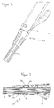
- Line trimmer 10 is configurable as a lawn trimmer (Figure 1A), for example, for use in trimming grass around tree trunks, washing lines etc, and as a lawn-edging apparatus (Figure 1B).
- Figure 1A a lawn trimmer
- Figure 1B a lawn-edging apparatus
- the line trimmer 10 includes a working head 11, a shaft 12 and a handle 13.
- the shaft 12 is fitted with a pair of supporting wheels 14 and associated wheel mount 15. Wheels 14 bear some of the weight of the working head and thus make the tool easier to move.
- Working head 11 includes a housing 20 for an electric motor (not shown) driving a line cutter head (not shown) of conventional type.
- Working head 11 further includes a cowl 21 around the cutter head to reduce distribution of grass cuttings away from the head and protect the user's feet from the cutter head.
- the handle 13 comprises a fixed hand grip 22 and an adjustable pivotable hand grip 23 which can be adjusted for user-comfort.
- the electric motor is connected to a mains supply at appropriate voltage by means of a cable 24 passing up the shaft of the trimmer 10, through handle 13 and terminating in a plug 25 to which a mains supply can be connected by means of an extension cable.
- the line trimmer is configurable between the lawn trimmer and edge-trimmer configurations by means of the shaft 12 being rotatable within the handle 13 between two defined positions 90° apart and securable by means of a clamp assembly 30, shown in more detail in Figures 2 to 7.
- the working head 11 is also pivotable about a working head pivot point 16 at a lower end of shaft 12 from the horizontal working configuration shown in Figure 1A to a vertical working configuration which, with the additional rotation of the shaft described above, is shown in Figure 1B.
- FIGS 2 and 3 show the clamp assembly 30, handle 13 and shaft 13 in the locked position
- Figures 4 and 5 show the clamp assembly in the unlocked position
- Clamp assembly 30 includes an elongate clamp shaft 31 forming a part of handle 13.
- Clamp shaft 31 is generally cylindrical in character to match the outer profile of the shaft 12, and is formed by a plurality of radially spaced clamp shaft elements.
- a clamp element spacing 32 between adjacent clamp elements 31 allows a degree of radial flexibility to the clamping elements 31a, 31b.
- Clamp shaft 31 includes an external threaded portion 33 for receipt of a corresponding internal thread 36 of a generally cylindrical clamp body 34.
- Clamp body 34 has an internal bearing surface 35 which, as clamp body 34 is screwed along threads 33, bears down upon clamping elements 31a, 31b, causing them to flex radially inwardly closing the spacing 32 between the adjacent elements 31a, 31b to bear against the outer surface of the shaft 12 inserted into the clamp assembly 13 and thereby frictionally secure it in place at a desired longitudinal and rotational position.
- Clamp assembly 13 includes a limiting arrangement to limit the degree of rotation of clamp body 34 required to loosen the clamping of clamping elements 31a, 31b against shaft 12.
- the pitch of the thread is selected to provide sufficient release of bearing force in response to the predetermined amount of rotation.
- the limiting arrangement comprises a clamp shaft limit stop 40 formed towards but spaced from the "locked" end of the thread of clamp-shaft threaded portion 33.
- a corresponding clamp body limit stop 41 bears, in the assembled tool, against the clamp shaft limit stop 40 to prevent further rotation (anti-clockwise as view in Figure 6) of clamp body 34 but is distorted by the reverse ramp face of the limit stop so as to pass readily over it in the clockwise direction during initial assembly.
- the apparatus further comprises a detent arrangement to hold the clamp body 34 in the locked position.
- the detent arrangement comprises a projection 42, suitably generally hemispherical, at the end of the thread of threaded portion 33 of the clamp shaft 31.
- a correspondingly-shaped recess 43 is formed in the corresponding part of clamp body 34.
- limiting arrangement 40,41 and detent arrangement 42,43 are each provided as opposed pairs of limit stops and detent components, to provide improved security.
- the shaft of the tool is formed with a plurality of uniformly spaced longitudinal grooves 50.
- just two grooves, radially separated by 90° are functionally equivalent.
- At least one of shaft grooves 50 cooperates with a location tab 51 formed on an inner surface of clamp shaft 34.
- Grooves 50 and tab 51 form a locating arrangement to ensure correct orientation of shaft 12 (and thus working head 11) with respect to the handle 13.
- By radially spacing the grooves by 90° accurate reconfiguration of the tool between the trimming and edging configurations is made easier and quicker.
- clamp body 34 is loosened, shaft 12 rotated in the appropriate direction and clamp body 34 re-tightened.
- Clamp elements 31a, 31b deform to allow tab 51 to pass over non-grooved portions of the shaft 12.
- two opposed location tabs 51 are provided, on opposed inner surfaces of clamp shaft 34, providing more resilient engagement of the clamp shaft 34 with grooves 50 of the tool shaft 12.
Landscapes
- Life Sciences & Earth Sciences (AREA)
- Environmental Sciences (AREA)
- Engineering & Computer Science (AREA)
- Mechanical Engineering (AREA)
- Soil Sciences (AREA)
- Harvester Elements (AREA)
Applications Claiming Priority (1)
| Application Number | Priority Date | Filing Date | Title |
|---|---|---|---|
| GB0417364A GB0417364D0 (en) | 2004-08-04 | 2004-08-04 | Garden tool adjustment |
Publications (2)
| Publication Number | Publication Date |
|---|---|
| EP1623615A1 true EP1623615A1 (de) | 2006-02-08 |
| EP1623615B1 EP1623615B1 (de) | 2012-06-13 |
Family
ID=32982511
Family Applications (1)
| Application Number | Title | Priority Date | Filing Date |
|---|---|---|---|
| EP20050107183 Expired - Lifetime EP1623615B1 (de) | 2004-08-04 | 2005-08-04 | Gartengerätverstellung |
Country Status (3)
| Country | Link |
|---|---|
| EP (1) | EP1623615B1 (de) |
| CN (1) | CN1732736B (de) |
| GB (1) | GB0417364D0 (de) |
Cited By (4)
| Publication number | Priority date | Publication date | Assignee | Title |
|---|---|---|---|---|
| EP2465337A1 (de) * | 2010-12-17 | 2012-06-20 | Viking GmbH | Handgeführtes Arbeitsgerät |
| FR2994541A1 (fr) * | 2012-08-20 | 2014-02-21 | Bosch Gmbh Robert | Dispositif de travail notamment outil de machine de jardinage |
| CN112352529A (zh) * | 2020-10-13 | 2021-02-12 | 无为市裴向东家庭农场 | 一种生态绿色水稻种植用杂草清理装置 |
| IT202200018939A1 (it) * | 2022-09-15 | 2024-03-15 | Stiga S P A In Breve Anche St S P A | Dispositivo per la manutenzione di terreni con attitudine ad assumere una configurazione di stazionamento |
Families Citing this family (7)
| Publication number | Priority date | Publication date | Assignee | Title |
|---|---|---|---|---|
| ES2558506T3 (es) * | 2012-10-26 | 2016-02-04 | Black & Decker Inc. | Dispositivo de corte de vegetación |
| CN104221581B (zh) * | 2013-04-12 | 2018-12-14 | 创科户外产品技术有限公司 | 植被切割机 |
| CN104365265A (zh) * | 2013-08-13 | 2015-02-25 | 天佑电器(苏州)有限公司 | 园林工具 |
| CN105265105A (zh) * | 2014-07-21 | 2016-01-27 | 苏州金莱克精密机械有限公司 | 园林工具 |
| DE102015207151A1 (de) | 2015-04-20 | 2016-10-20 | Robert Bosch Gmbh | Befestigungsmittel für Handwerkzeugmaschine |
| CN117063698B (zh) * | 2022-05-10 | 2026-01-23 | 莱克电气绿能科技(苏州)有限公司 | 气浮割草装置 |
| EP4729242A1 (de) * | 2024-10-16 | 2026-04-22 | Techtronic Cordless GP | Höhenverstellbares elektrowerkzeug |
Citations (7)
| Publication number | Priority date | Publication date | Assignee | Title |
|---|---|---|---|---|
| DE3625287A1 (de) * | 1986-07-25 | 1988-02-04 | Gardena Kress & Kastner Gmbh | Teleskopstiel |
| DE29604237U1 (de) * | 1996-03-07 | 1996-05-02 | Hsu, Shih-Hao, Bi Tou Hsiang, Changhua | Gartenwerkzeug |
| US5662428A (en) * | 1993-11-09 | 1997-09-02 | Black & Decker Inc. | Shaft assembly |
| EP0893045A1 (de) * | 1997-07-23 | 1999-01-27 | McCULLOCH CORPORATION | Wellen- Rotations- und teleskopischer Einstellmechanismus für Gartengerät |
| DE29820433U1 (de) * | 1998-11-16 | 1999-01-28 | Kress-Elektrik GmbH & Co Elektromotorenfabrik, 72406 Bisingen | Vorsatz für Elektrohandwerkzeuge |
| DE19827061A1 (de) * | 1998-06-18 | 1999-12-23 | Gardena Kress & Kastner Gmbh | Befestigungseinrichtung zur lösbaren Befestigung eines Arbeitsgerätes an einem Stiel |
| WO2004090349A1 (en) * | 2003-04-14 | 2004-10-21 | Jussi Petteri Heinonen | Telescopic handle |
Family Cites Families (1)
| Publication number | Priority date | Publication date | Assignee | Title |
|---|---|---|---|---|
| US6189627B1 (en) * | 1999-07-13 | 2001-02-20 | Ame Group, Incorporated | Lawn and garden tool |
-
2004
- 2004-08-04 GB GB0417364A patent/GB0417364D0/en not_active Ceased
-
2005
- 2005-08-04 CN CN 200510088575 patent/CN1732736B/zh not_active Expired - Fee Related
- 2005-08-04 EP EP20050107183 patent/EP1623615B1/de not_active Expired - Lifetime
Patent Citations (7)
| Publication number | Priority date | Publication date | Assignee | Title |
|---|---|---|---|---|
| DE3625287A1 (de) * | 1986-07-25 | 1988-02-04 | Gardena Kress & Kastner Gmbh | Teleskopstiel |
| US5662428A (en) * | 1993-11-09 | 1997-09-02 | Black & Decker Inc. | Shaft assembly |
| DE29604237U1 (de) * | 1996-03-07 | 1996-05-02 | Hsu, Shih-Hao, Bi Tou Hsiang, Changhua | Gartenwerkzeug |
| EP0893045A1 (de) * | 1997-07-23 | 1999-01-27 | McCULLOCH CORPORATION | Wellen- Rotations- und teleskopischer Einstellmechanismus für Gartengerät |
| DE19827061A1 (de) * | 1998-06-18 | 1999-12-23 | Gardena Kress & Kastner Gmbh | Befestigungseinrichtung zur lösbaren Befestigung eines Arbeitsgerätes an einem Stiel |
| DE29820433U1 (de) * | 1998-11-16 | 1999-01-28 | Kress-Elektrik GmbH & Co Elektromotorenfabrik, 72406 Bisingen | Vorsatz für Elektrohandwerkzeuge |
| WO2004090349A1 (en) * | 2003-04-14 | 2004-10-21 | Jussi Petteri Heinonen | Telescopic handle |
Cited By (5)
| Publication number | Priority date | Publication date | Assignee | Title |
|---|---|---|---|---|
| EP2465337A1 (de) * | 2010-12-17 | 2012-06-20 | Viking GmbH | Handgeführtes Arbeitsgerät |
| EP2676537A2 (de) | 2010-12-17 | 2013-12-25 | Viking GmbH | Handgeführtes Arbeitsgerät |
| FR2994541A1 (fr) * | 2012-08-20 | 2014-02-21 | Bosch Gmbh Robert | Dispositif de travail notamment outil de machine de jardinage |
| CN112352529A (zh) * | 2020-10-13 | 2021-02-12 | 无为市裴向东家庭农场 | 一种生态绿色水稻种植用杂草清理装置 |
| IT202200018939A1 (it) * | 2022-09-15 | 2024-03-15 | Stiga S P A In Breve Anche St S P A | Dispositivo per la manutenzione di terreni con attitudine ad assumere una configurazione di stazionamento |
Also Published As
| Publication number | Publication date |
|---|---|
| CN1732736B (zh) | 2010-09-08 |
| GB0417364D0 (en) | 2004-09-08 |
| CN1732736A (zh) | 2006-02-15 |
| EP1623615B1 (de) | 2012-06-13 |
Similar Documents
| Publication | Publication Date | Title |
|---|---|---|
| EP1623615B1 (de) | Gartengerätverstellung | |
| US4829755A (en) | Trimmer wheels | |
| US4268964A (en) | Apparatus for cutting, trimming and edging vegetation and the like | |
| US9854738B2 (en) | String trimmer with adjustable guard assembly | |
| US6260278B1 (en) | Hand-held lawn and brush trimmer having manual trimmer head adjustment mechanisms | |
| EP0005540B1 (de) | Fadenschneider zum Beschneiden von Rasenkanten | |
| US8984718B2 (en) | Handle height adjustment device of walk-behind power tool, a handle assembly and a walk-behind power tool comprising such a device | |
| EP2966967B1 (de) | Schnellkupplung für mäherschaufeln | |
| US20170006775A1 (en) | Combination blade and cord weed cutter-trimmer head device | |
| WO2023278734A1 (en) | String trimmer head | |
| US5287683A (en) | Sweep cut trimmer mower and converting platform | |
| US20120167399A1 (en) | Edge-trimmer | |
| WO2018068324A1 (en) | Line trimmer | |
| US7036297B2 (en) | Trimmer attachment | |
| US6971223B2 (en) | Wheeled trimmer device of adjustable height | |
| US20090188354A1 (en) | Combination Vegetation trimmer and edger | |
| US20140053416A1 (en) | Protective Wear Cap For Flexible Line Rotary Trimmer Heads | |
| DE10332918B4 (de) | Gartengerät, insbesondere Fadenschneider | |
| US4852658A (en) | Mounted edger | |
| US20030093983A1 (en) | Maneuverable and adjustable lawn mower having an edger-trimming unit | |
| US11968934B2 (en) | Lawn trimmer attachment for trimming sprinkler heads | |
| US12193372B2 (en) | Adjustable lawn edging attachment for trimming around sprinkler heads | |
| US2719398A (en) | Lawn trimmer | |
| US12484475B2 (en) | Integrated trimmer for a lawn mower | |
| US12295284B2 (en) | Adjustable grass trimmer attachment |
Legal Events
| Date | Code | Title | Description |
|---|---|---|---|
| PUAI | Public reference made under article 153(3) epc to a published international application that has entered the european phase |
Free format text: ORIGINAL CODE: 0009012 |
|
| AK | Designated contracting states |
Kind code of ref document: A1 Designated state(s): AT BE BG CH CY CZ DE DK EE ES FI FR GB GR HU IE IS IT LI LT LU LV MC NL PL PT RO SE SI SK TR |
|
| AX | Request for extension of the european patent |
Extension state: AL BA HR MK YU |
|
| 17P | Request for examination filed |
Effective date: 20060803 |
|
| 17Q | First examination report despatched |
Effective date: 20060901 |
|
| AKX | Designation fees paid |
Designated state(s): AT BE BG CH CY CZ DE DK EE ES FI FR GB GR HU IE IS IT LI LT LU LV MC NL PL PT RO SE SI SK TR |
|
| GRAJ | Information related to disapproval of communication of intention to grant by the applicant or resumption of examination proceedings by the epo deleted |
Free format text: ORIGINAL CODE: EPIDOSDIGR1 |
|
| GRAP | Despatch of communication of intention to grant a patent |
Free format text: ORIGINAL CODE: EPIDOSNIGR1 |
|
| GRAP | Despatch of communication of intention to grant a patent |
Free format text: ORIGINAL CODE: EPIDOSNIGR1 |
|
| GRAS | Grant fee paid |
Free format text: ORIGINAL CODE: EPIDOSNIGR3 |
|
| GRAA | (expected) grant |
Free format text: ORIGINAL CODE: 0009210 |
|
| AK | Designated contracting states |
Kind code of ref document: B1 Designated state(s): AT BE BG CH CY CZ DE DK EE ES FI FR GB GR HU IE IS IT LI LT LU LV MC NL PL PT RO SE SI SK TR |
|
| REG | Reference to a national code |
Ref country code: GB Ref legal event code: FG4D |
|
| REG | Reference to a national code |
Ref country code: CH Ref legal event code: EP Ref country code: AT Ref legal event code: REF Ref document number: 561550 Country of ref document: AT Kind code of ref document: T Effective date: 20120615 |
|
| REG | Reference to a national code |
Ref country code: IE Ref legal event code: FG4D |
|
| REG | Reference to a national code |
Ref country code: DE Ref legal event code: R096 Ref document number: 602005034629 Country of ref document: DE Effective date: 20120816 |
|
| REG | Reference to a national code |
Ref country code: NL Ref legal event code: VDEP Effective date: 20120613 |
|
| PG25 | Lapsed in a contracting state [announced via postgrant information from national office to epo] |
Ref country code: LT Free format text: LAPSE BECAUSE OF FAILURE TO SUBMIT A TRANSLATION OF THE DESCRIPTION OR TO PAY THE FEE WITHIN THE PRESCRIBED TIME-LIMIT Effective date: 20120613 Ref country code: SE Free format text: LAPSE BECAUSE OF FAILURE TO SUBMIT A TRANSLATION OF THE DESCRIPTION OR TO PAY THE FEE WITHIN THE PRESCRIBED TIME-LIMIT Effective date: 20120613 Ref country code: CY Free format text: LAPSE BECAUSE OF FAILURE TO SUBMIT A TRANSLATION OF THE DESCRIPTION OR TO PAY THE FEE WITHIN THE PRESCRIBED TIME-LIMIT Effective date: 20120613 Ref country code: FI Free format text: LAPSE BECAUSE OF FAILURE TO SUBMIT A TRANSLATION OF THE DESCRIPTION OR TO PAY THE FEE WITHIN THE PRESCRIBED TIME-LIMIT Effective date: 20120613 |
|
| REG | Reference to a national code |
Ref country code: AT Ref legal event code: MK05 Ref document number: 561550 Country of ref document: AT Kind code of ref document: T Effective date: 20120613 |
|
| REG | Reference to a national code |
Ref country code: LT Ref legal event code: MG4D Effective date: 20120613 |
|
| PG25 | Lapsed in a contracting state [announced via postgrant information from national office to epo] |
Ref country code: SI Free format text: LAPSE BECAUSE OF FAILURE TO SUBMIT A TRANSLATION OF THE DESCRIPTION OR TO PAY THE FEE WITHIN THE PRESCRIBED TIME-LIMIT Effective date: 20120613 Ref country code: LV Free format text: LAPSE BECAUSE OF FAILURE TO SUBMIT A TRANSLATION OF THE DESCRIPTION OR TO PAY THE FEE WITHIN THE PRESCRIBED TIME-LIMIT Effective date: 20120613 Ref country code: GR Free format text: LAPSE BECAUSE OF FAILURE TO SUBMIT A TRANSLATION OF THE DESCRIPTION OR TO PAY THE FEE WITHIN THE PRESCRIBED TIME-LIMIT Effective date: 20120914 |
|
| PG25 | Lapsed in a contracting state [announced via postgrant information from national office to epo] |
Ref country code: RO Free format text: LAPSE BECAUSE OF FAILURE TO SUBMIT A TRANSLATION OF THE DESCRIPTION OR TO PAY THE FEE WITHIN THE PRESCRIBED TIME-LIMIT Effective date: 20120613 Ref country code: IS Free format text: LAPSE BECAUSE OF FAILURE TO SUBMIT A TRANSLATION OF THE DESCRIPTION OR TO PAY THE FEE WITHIN THE PRESCRIBED TIME-LIMIT Effective date: 20121013 Ref country code: SK Free format text: LAPSE BECAUSE OF FAILURE TO SUBMIT A TRANSLATION OF THE DESCRIPTION OR TO PAY THE FEE WITHIN THE PRESCRIBED TIME-LIMIT Effective date: 20120613 Ref country code: CZ Free format text: LAPSE BECAUSE OF FAILURE TO SUBMIT A TRANSLATION OF THE DESCRIPTION OR TO PAY THE FEE WITHIN THE PRESCRIBED TIME-LIMIT Effective date: 20120613 Ref country code: BE Free format text: LAPSE BECAUSE OF FAILURE TO SUBMIT A TRANSLATION OF THE DESCRIPTION OR TO PAY THE FEE WITHIN THE PRESCRIBED TIME-LIMIT Effective date: 20120613 Ref country code: AT Free format text: LAPSE BECAUSE OF FAILURE TO SUBMIT A TRANSLATION OF THE DESCRIPTION OR TO PAY THE FEE WITHIN THE PRESCRIBED TIME-LIMIT Effective date: 20120613 Ref country code: EE Free format text: LAPSE BECAUSE OF FAILURE TO SUBMIT A TRANSLATION OF THE DESCRIPTION OR TO PAY THE FEE WITHIN THE PRESCRIBED TIME-LIMIT Effective date: 20120613 |
|
| PG25 | Lapsed in a contracting state [announced via postgrant information from national office to epo] |
Ref country code: PT Free format text: LAPSE BECAUSE OF FAILURE TO SUBMIT A TRANSLATION OF THE DESCRIPTION OR TO PAY THE FEE WITHIN THE PRESCRIBED TIME-LIMIT Effective date: 20121015 Ref country code: PL Free format text: LAPSE BECAUSE OF FAILURE TO SUBMIT A TRANSLATION OF THE DESCRIPTION OR TO PAY THE FEE WITHIN THE PRESCRIBED TIME-LIMIT Effective date: 20120613 Ref country code: IT Free format text: LAPSE BECAUSE OF FAILURE TO SUBMIT A TRANSLATION OF THE DESCRIPTION OR TO PAY THE FEE WITHIN THE PRESCRIBED TIME-LIMIT Effective date: 20120613 |
|
| REG | Reference to a national code |
Ref country code: CH Ref legal event code: PL |
|
| PG25 | Lapsed in a contracting state [announced via postgrant information from national office to epo] |
Ref country code: NL Free format text: LAPSE BECAUSE OF FAILURE TO SUBMIT A TRANSLATION OF THE DESCRIPTION OR TO PAY THE FEE WITHIN THE PRESCRIBED TIME-LIMIT Effective date: 20120613 Ref country code: MC Free format text: LAPSE BECAUSE OF NON-PAYMENT OF DUE FEES Effective date: 20120831 |
|
| PLBE | No opposition filed within time limit |
Free format text: ORIGINAL CODE: 0009261 |
|
| STAA | Information on the status of an ep patent application or granted ep patent |
Free format text: STATUS: NO OPPOSITION FILED WITHIN TIME LIMIT |
|
| PG25 | Lapsed in a contracting state [announced via postgrant information from national office to epo] |
Ref country code: DK Free format text: LAPSE BECAUSE OF FAILURE TO SUBMIT A TRANSLATION OF THE DESCRIPTION OR TO PAY THE FEE WITHIN THE PRESCRIBED TIME-LIMIT Effective date: 20120613 Ref country code: ES Free format text: LAPSE BECAUSE OF FAILURE TO SUBMIT A TRANSLATION OF THE DESCRIPTION OR TO PAY THE FEE WITHIN THE PRESCRIBED TIME-LIMIT Effective date: 20120924 Ref country code: CH Free format text: LAPSE BECAUSE OF NON-PAYMENT OF DUE FEES Effective date: 20120831 Ref country code: LI Free format text: LAPSE BECAUSE OF NON-PAYMENT OF DUE FEES Effective date: 20120831 |
|
| 26N | No opposition filed |
Effective date: 20130314 |
|
| REG | Reference to a national code |
Ref country code: IE Ref legal event code: MM4A |
|
| REG | Reference to a national code |
Ref country code: DE Ref legal event code: R097 Ref document number: 602005034629 Country of ref document: DE Effective date: 20130314 |
|
| PG25 | Lapsed in a contracting state [announced via postgrant information from national office to epo] |
Ref country code: BG Free format text: LAPSE BECAUSE OF FAILURE TO SUBMIT A TRANSLATION OF THE DESCRIPTION OR TO PAY THE FEE WITHIN THE PRESCRIBED TIME-LIMIT Effective date: 20120913 Ref country code: IE Free format text: LAPSE BECAUSE OF NON-PAYMENT OF DUE FEES Effective date: 20120804 |
|
| PG25 | Lapsed in a contracting state [announced via postgrant information from national office to epo] |
Ref country code: TR Free format text: LAPSE BECAUSE OF FAILURE TO SUBMIT A TRANSLATION OF THE DESCRIPTION OR TO PAY THE FEE WITHIN THE PRESCRIBED TIME-LIMIT Effective date: 20120613 |
|
| PG25 | Lapsed in a contracting state [announced via postgrant information from national office to epo] |
Ref country code: LU Free format text: LAPSE BECAUSE OF NON-PAYMENT OF DUE FEES Effective date: 20120804 |
|
| PG25 | Lapsed in a contracting state [announced via postgrant information from national office to epo] |
Ref country code: HU Free format text: LAPSE BECAUSE OF FAILURE TO SUBMIT A TRANSLATION OF THE DESCRIPTION OR TO PAY THE FEE WITHIN THE PRESCRIBED TIME-LIMIT Effective date: 20050804 |
|
| REG | Reference to a national code |
Ref country code: FR Ref legal event code: PLFP Year of fee payment: 12 |
|
| REG | Reference to a national code |
Ref country code: FR Ref legal event code: PLFP Year of fee payment: 13 |
|
| PGFP | Annual fee paid to national office [announced via postgrant information from national office to epo] |
Ref country code: FR Payment date: 20170823 Year of fee payment: 13 |
|
| PG25 | Lapsed in a contracting state [announced via postgrant information from national office to epo] |
Ref country code: FR Free format text: LAPSE BECAUSE OF NON-PAYMENT OF DUE FEES Effective date: 20180831 |
|
| PGFP | Annual fee paid to national office [announced via postgrant information from national office to epo] |
Ref country code: GB Payment date: 20190827 Year of fee payment: 15 |
|
| PGFP | Annual fee paid to national office [announced via postgrant information from national office to epo] |
Ref country code: DE Payment date: 20201021 Year of fee payment: 16 |
|
| REG | Reference to a national code |
Ref country code: DE Ref legal event code: R084 Ref document number: 602005034629 Country of ref document: DE |
|
| GBPC | Gb: european patent ceased through non-payment of renewal fee |
Effective date: 20200804 |
|
| PG25 | Lapsed in a contracting state [announced via postgrant information from national office to epo] |
Ref country code: GB Free format text: LAPSE BECAUSE OF NON-PAYMENT OF DUE FEES Effective date: 20200804 |
|
| REG | Reference to a national code |
Ref country code: DE Ref legal event code: R119 Ref document number: 602005034629 Country of ref document: DE |
|
| PG25 | Lapsed in a contracting state [announced via postgrant information from national office to epo] |
Ref country code: DE Free format text: LAPSE BECAUSE OF NON-PAYMENT OF DUE FEES Effective date: 20220301 |