EP1623748B1 - Élément filtrant et filtre comprenant une multitude d'éléments filtrants superposés axialement. - Google Patents
Élément filtrant et filtre comprenant une multitude d'éléments filtrants superposés axialement. Download PDFInfo
- Publication number
- EP1623748B1 EP1623748B1 EP05105811A EP05105811A EP1623748B1 EP 1623748 B1 EP1623748 B1 EP 1623748B1 EP 05105811 A EP05105811 A EP 05105811A EP 05105811 A EP05105811 A EP 05105811A EP 1623748 B1 EP1623748 B1 EP 1623748B1
- Authority
- EP
- European Patent Office
- Prior art keywords
- filtering
- filter
- dielectric fluid
- filtering element
- spokes
- Prior art date
- Legal status (The legal status is an assumption and is not a legal conclusion. Google has not performed a legal analysis and makes no representation as to the accuracy of the status listed.)
- Expired - Lifetime
Links
Images


Classifications
-
- B—PERFORMING OPERATIONS; TRANSPORTING
- B01—PHYSICAL OR CHEMICAL PROCESSES OR APPARATUS IN GENERAL
- B01D—SEPARATION
- B01D29/00—Filters with filtering elements stationary during filtration, e.g. pressure or suction filters, not covered by groups B01D24/00 - B01D27/00; Filtering elements therefor
- B01D29/44—Edge filtering elements, i.e. using contiguous impervious surfaces
- B01D29/46—Edge filtering elements, i.e. using contiguous impervious surfaces of flat, stacked bodies
Definitions
- the present invention refers to a filtering element and to a filter comprising a plurality of filtering elements axially stacked and pressed on one another.
- the present invention refers to a filter and to a filtering element fitted to filter a water base dielectric fluid used in machinery such as wire electroerosion machines, milling cutters, grinding machines, turning machines and so on.
- the poor quality of a filter that purifies the dielectric fluid used by the machine itself can cause a number of inconveniences such as, among others, the inadequate quality of the manufactured surface and the insufficient accuracy in the manufactured articles sizes, the clogging of the washing nozzles, the increase in the resin consumption, the dirt deposit in the cooling system and piping and the increase of the corrosion residues.
- Filters consisting of axially stacked elements are known in the art.
- EP 1291058 discloses a filter comprising a plurality of discoidal filtering elements axially stacked and pressed so as to form a compact assembly.
- said discoidal filtering elements do not have openings, that is they are solid, and so they increase the weight and the total size of the filter in which they are arranged in a stack.
- a first object of the present invention is, therefore, to provide a filter comprising a plurality of filtering elements having a shape such as to increase the filtration area of the filter without having to increase the size of the total surface of the filtering elements or the length of the stack of filtering elements to achieve the same filtering surface and the same filtration degree.
- a further object of the present invention is, therefore, to obtain a filtering element, suitable for filtration of a water base dielectric fluid, made of a treated paper base material allowing to more effectively keep the impurities to be filtered present in the dielectric fluid.
- a filtering element and a filter comprising a plurality of pressed and axially stacked filtering elements, made according to the present invention.
- an optimal operation of the machinery using the dielectric fluid filtered by the filter according to the present invention is achieved, with a resulting high manufacturing quality of the pieces.
- a further advantage is that the filter according to the present invention can be defined as ecological because it does not need, for its operation, any additional substance, such as for instance fossil meal, quartzite and so on, thus collecting a material to be disposed of that turns out to be made simply of the material that has been removed during the machine manufacturing cycle.
- the filter according to the present invention is advantageously self-cleaning since it can be repeatedly and automatically cleaned without stopping the machine manufacturing cycle.
- the filter according to the present invention advantageously eliminates all the costs for replacement, maintenance and disposal of the known art filters (cartridges) thus allowing a considerable economic saving with a productivity increase and further providing the possibility of achieving the cleanliness degree of the dielectric fluid required by the manufacturer of the machinery in which the fluid is used.
- a filter 1 according to the invention having a substantially cylindrical shape, comprising a plurality of filtering elements 10 axially stacked and pressed on one another so as to obtain a compact filtering structure.
- Filter 1 is delimited, at its two ends, by two metal discs, an upper one 3 and a lower one 4.
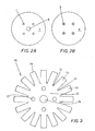
- Upper disc 3 has a central hole 5 for the passage of the decontaminated dielectric fluid and four equidistant central holes 7 for the insertion of four tie-rods 9 that are fastened to disc 4.
- the filtering elements 10 are pressed with the help of tie-rods 9 as well as of a proper machinery, so that no gaps turn out to be present between two adjacent filtering elements 10.
- Filter 1 can be contained inside a casing, not shown, having an inlet for the contaminated fluid and an outlet for the purified fluid or can be mounted onto a filters-holder support installed inside a filtration bulb, that will be subsequently illustrated in detail.
- the water base dielectric fluid is a fluid used in machinery such as wire electroerosion machines, milling cutters, grinding machines, turning machines and so on, and can consist of demineralized water or of a water-oil emulsion.
- a filtering element 10 according to the invention is illustrated in detail, the filtering element being substantially inscribable in a circumference and comprising a circular central region 12, from the periphery of which a plurality of spokes 13 radially depart, said spokes being equidistant therebetween, having the same length and ending on said circumference so as to form interstices 15 having a rounded tip 18.
- Spokes 13 have a substantially rectangular shape with ends edges 14 that can be rounded or squared.
- the circular central region 12 comprises a central hole 19, alignable with hole 5 of the metal disc 3, through which the dielectric fluid being filtered by the filtering element 10 flows. Between the central hole 19 and the spokes 13 four peripheral holes 17, mutually equidistant, are provided, that are used to insert the respective tie-rods 9 onto which a plurality of filtering elements 10 is stacked.
- Such material consists of resin impregnated paper.
- the filtration degree achievable with a filter consisting of filtering elements 10 made of such a material is 3 ⁇ m.
- FIG. 4 an example of application of the filter according to the invention is illustrated, in a system 30 used to decontaminate a dielectric fluid, particularly demineralized water, used in a wire electroerosion machine with the respective self-cleaning system of the filtering elements.
- a dielectric fluid particularly demineralized water
- a contaminated dielectric fluid flows through a duct 32 into a decantation basin 33, which comprises a baffle 47 to separate a compartment 48 for the contaminated fluid from a compartment 46 for the purified fluid.
- the contaminated fluid flows through a duct 35 towards the inlet 37 of a filtration bulb 39 made of stainless steel.
- the filtration bulb 39 comprises at least one filter 1 according to the invention consisting of a filtering elements 10 stack.
- a filtering elements 10 stack Preferably, in order to increase the filtration surface, seven filters 1 are used, which are arranged on a filters-holder support having a disc shape, not shown, so that one of said filters 1 is centrally arranged on the filters-holder support and the other six filters 1 are arranged at the periphery of the filters-holder support.
- the number of filters of the filters-holder support can be varied depending on the fluid to be filtered and on the machine operation needs.
- Bulb 39 is moreover provided with a cover 41 protecting filters 1 from the external environment and allowing a quick access inside the bulb 39 for a possible replacement or maintenance of filters 1.
- the purified fluid flows out from an upper outlet 43 of the bulb 39 and flows through a duct 45 to end into the compartment 46 of the decantation basin 33 from which, pumped by a pump 49, is introduced again into the basin 31 of the wire electroerosion machine, ready to be used in a manufacturing cycle of such machine.
- the impurities settled on the filtering elements 10 of filters 1 are discharged by introducing pressurized air from top of the bulb 39 through a duct 57 laterally arranged on the cover 41 of the bulb 39. During its path towards the lower portion of the bulb 39, the pressurized air removes from filtering elements 10 of filters 1 the impurities settled on them during the filtration process.
- Such impurities are made to flow out from a duct 61 arranged below bulb 39 and are collected in a collector that is emptied at regular intervals.
- System 30 is automatically controlled from a control device, not shown, that provides to operate the pump 34 as well as to open and close valves 55,53,57,59 that respectively operate the entry to bulb 39 of the contaminated dielectric fluid, the exit from bulb 39 of the purified dielectric fluid, the air introduction into bulb 39 for the filters 1 cleaning and the discharge of the impurities into the proper collector 63.
- the filtering element 10 has been disclosed as having a shape inscribable in a circumference. However, it can have a shape inscribable in a square, an ellipse, a rectangle or other geometrical surfaces depending on the applications.
- spokes 13 of the filtering element 10 instead of being all of the same length, can moreover have different lengths.
- the hole for the passage of the dielectric fluid can also be provided in a non-central position with respect to region 12.
- the filtering element 10 can also be without holes 17 for the tie-rods 9.
- the filtering elements can be stacked and pressed by operating for instance from the outside on the metal discs 3 and 4.
Landscapes
- Chemical & Material Sciences (AREA)
- Chemical Kinetics & Catalysis (AREA)
- Filtration Of Liquid (AREA)
- Filtering Of Dispersed Particles In Gases (AREA)
- Filtering Materials (AREA)
- Filters And Equalizers (AREA)
- Devices For Use In Laboratory Experiments (AREA)
- Control Of Motors That Do Not Use Commutators (AREA)
Claims (14)
- Elément filtrant (10) permettant de filtrer un fluide diélectrique à base d'eau comprenant une zone centrale (12), dans laquelle est formé un trou central (19) pour le passage axial dudit fluide diélectrique, et une pluralité de bras (13) s'étendant radialement à partir de la périphérie de la zone centrale (12) de façon à former des interstices respectifs (15) entre deux bras adjacents (13), caractérisé en ce que ledit élément filtrant (10) est constitué de papier imprégné de résine.
- Elément filtrant (10) selon la revendication 1, dans lequel, dans ladite zone centrale (12), au moins un trou (17), de préférence quatre, est (sont) réalisé(s), de plus, pour le passage d'une tige de raccordement (9) utilisée pour empiler axialement et presser mutuellement une pluralité desdits éléments filtrants (10).
- Elément filtrant (10) selon la revendication 1 ou 2, dans lequel lesdits bras (13) présentent une configuration essentiellement rectangulaire.
- Elément filtrant (10) selon l'une des revendications précédentes, dans lequel lesdits bras (13) sont mutuellement équidistants.
- Elément filtrant selon l'une des revendications précédentes, dans lequel tous lesdits bras (13) ont la même longueur.
- Elément filtrant selon l'une des revendications précédentes, dans lequel ladite zone centrale (12) présente une configuration circulaire.
- Elément filtrant (10) selon l'une des revendications précédentes, dans lequel lesdits bras (13) comportent un bord (14) doté d'une extrémité arrondie ou carrée et dans lequel ledit interstice (15) comporte, de façon correspondante à ladite périphérie de la zone centrale (12) une pointe arrondie (18).
- Filtre (1) servant à filtrer un fluide diélectrique comportant une pluralité d'éléments filtrants selon l'une des revendications précédentes, lesdits éléments (10) étant empilés axialement et mutuellement comprimés.
- Filtre (1) selon la revendication 8, dans lequel ledit filtre est délimité, au niveau de ses extrémités, par un disque métallique supérieur (3) et par un disque métallique inférieur (4), ledit disque supérieur (3) comportant un trou (5) destiné au passage dudit fluide diélectrique et au moins un trou (7) destiné au passage d'une tige de raccordement (9) qui est fixée au dit disque inférieur (4).
- Filtre (1) selon la revendication 9, dans lequel lesdits éléments filtrants (10) et lesdits disques (3, 4) sont contenus à l'intérieur d'un boîtier dans lequel un orifice d'entrée destiné au fluide diélectrique contaminé et un orifice de sortie destiné au fluide diélectrique purifié sont formés.
- Filtre (1) selon l'une des revendications 8 à 10, dans lequel ledit filtre est autonettoyant.
- Système (30) pour purifier un fluide diélectrique à base d'eau utilisé dans le cycle de fabrication d'une machine outil, particulièrement d'une machine d'électroérosion à fil métallique, comportant une ampoule de filtration (39) à l'intérieur de laquelle un support de porte-filtres est prévu, sur lequel au moins un filtre (1) selon la revendication 8 est monté.
- Système (30) selon la revendication 12, dans lequel ledit au moins un filtre (1) est autonettoyant.
- Procédé pour fabriquer un filtre (1) permettant de filtrer un fluide diélectrique comprenant les étapes consistant à :- fournir une pluralité d'éléments filtrants (10) selon l'une des revendications précédentes 1 à 7 ;- fournir un disque métallique supérieur (3), un disque métallique inférieur (4) et au moins une tige de raccordement (9), ledit disque supérieur (3) comportant un trou (5) destiné au passage dudit fluide diélectrique et au moins un trou (7) destiné au passage de ladite, au moins une, tige de raccordement (9) qui est fixée audit disque inférieur (4) ;- empiler axialement et comprimer mutuellement lesdits éléments filtrants (10) entre ledit disque supérieur (3) et ledit disque inférieur (4) à l'aide de ladite, au moins une, tige de raccordement (9) de façon qu'aucune formation d'intervalle ne se produise entre deux éléments filtrants adjacents (10).
Applications Claiming Priority (1)
| Application Number | Priority Date | Filing Date | Title |
|---|---|---|---|
| IT000557A ITTO20040557A1 (it) | 2004-08-06 | 2004-08-06 | Elemento filtrante e filtro comprendente una pluralita' di elementi filtranti impilati assialmente |
Publications (3)
| Publication Number | Publication Date |
|---|---|
| EP1623748A2 EP1623748A2 (fr) | 2006-02-08 |
| EP1623748A3 EP1623748A3 (fr) | 2006-03-01 |
| EP1623748B1 true EP1623748B1 (fr) | 2009-04-15 |
Family
ID=35432463
Family Applications (1)
| Application Number | Title | Priority Date | Filing Date |
|---|---|---|---|
| EP05105811A Expired - Lifetime EP1623748B1 (fr) | 2004-08-06 | 2005-06-29 | Élément filtrant et filtre comprenant une multitude d'éléments filtrants superposés axialement. |
Country Status (4)
| Country | Link |
|---|---|
| EP (1) | EP1623748B1 (fr) |
| AT (1) | ATE428479T1 (fr) |
| DE (1) | DE602005013863D1 (fr) |
| IT (1) | ITTO20040557A1 (fr) |
Families Citing this family (1)
| Publication number | Priority date | Publication date | Assignee | Title |
|---|---|---|---|---|
| DE102015002498A1 (de) * | 2015-02-27 | 2016-09-01 | Dürr Systems GmbH | Abscheidevorrichtung zum Abscheiden von Partikeln |
Citations (1)
| Publication number | Priority date | Publication date | Assignee | Title |
|---|---|---|---|---|
| US5393423A (en) * | 1987-02-03 | 1995-02-28 | Drori; Mordeki | Filter apparatus |
Family Cites Families (4)
| Publication number | Priority date | Publication date | Assignee | Title |
|---|---|---|---|---|
| US2327648A (en) * | 1942-10-17 | 1943-08-24 | Ralph L Skinner | Filter pack |
| GB2239612A (en) * | 1990-01-06 | 1991-07-10 | Multone Limited | Edge filter |
| US5580454A (en) * | 1995-11-03 | 1996-12-03 | Zaiter; Sohail | Backwashing filter with increased filtration surface area |
| CA2301992A1 (fr) * | 2000-03-23 | 2001-09-23 | Bernard Juneau | Pre-filtre pour fosse septique |
-
2004
- 2004-08-06 IT IT000557A patent/ITTO20040557A1/it unknown
-
2005
- 2005-06-29 AT AT05105811T patent/ATE428479T1/de not_active IP Right Cessation
- 2005-06-29 EP EP05105811A patent/EP1623748B1/fr not_active Expired - Lifetime
- 2005-06-29 DE DE602005013863T patent/DE602005013863D1/de not_active Expired - Lifetime
Patent Citations (1)
| Publication number | Priority date | Publication date | Assignee | Title |
|---|---|---|---|---|
| US5393423A (en) * | 1987-02-03 | 1995-02-28 | Drori; Mordeki | Filter apparatus |
Also Published As
| Publication number | Publication date |
|---|---|
| DE602005013863D1 (de) | 2009-05-28 |
| EP1623748A3 (fr) | 2006-03-01 |
| ITTO20040557A1 (it) | 2004-11-06 |
| ATE428479T1 (de) | 2009-05-15 |
| EP1623748A2 (fr) | 2006-02-08 |
Similar Documents
| Publication | Publication Date | Title |
|---|---|---|
| US8496117B2 (en) | Self cleaning, continuously operating filter apparatus for fluids | |
| CN1923459B (zh) | 具有冷却液过滤装置的切屑输送机 | |
| US10596497B2 (en) | Filter scraper | |
| US20130193056A1 (en) | Filtering apparatus | |
| EP0124246A2 (fr) | Filtre | |
| CA2738247A1 (fr) | Un systeme de filtrage double servant a filtrer un fluide | |
| WO1994009881A1 (fr) | Appareil filtre pour liquide de refroidissement de machine-outil | |
| EP0946248A1 (fr) | Filtre a clarification a contre-flux | |
| DE69406771T2 (de) | Oel-reinigungsanlage für motoren | |
| EP1623748B1 (fr) | Élément filtrant et filtre comprenant une multitude d'éléments filtrants superposés axialement. | |
| US5158691A (en) | Filter apparatus and method for filtering contaminants from machine tool coolant | |
| JP4198353B2 (ja) | 工業用油の濾過装置 | |
| WO1997032651A1 (fr) | Filtre conique pour fluides | |
| US2859876A (en) | Filter | |
| JP5756578B1 (ja) | 切削液浄化装置 | |
| KR20250078331A (ko) | 자동 회전 역세척 정밀 여과 장치 | |
| KR101596480B1 (ko) | 여과판의 스크래핑이 가능한 여과장치 | |
| KR20090106961A (ko) | 셀프 클리닝 필터 장치 | |
| KR20120045818A (ko) | 오일 필터 제어방법 | |
| EP1222011B1 (fr) | Ensemble filtre | |
| JPH01310710A (ja) | 逆洗可能なプレコートフィルターエレメントの隔壁 | |
| KR200176953Y1 (ko) | 원반형 필터 | |
| KR102448339B1 (ko) | 재생이 쉬운 가공액 필터 장치 | |
| GB2374556A (en) | Disc Filtration Device | |
| JP2007098341A (ja) | 沈殿分離装置 |
Legal Events
| Date | Code | Title | Description |
|---|---|---|---|
| PUAI | Public reference made under article 153(3) epc to a published international application that has entered the european phase |
Free format text: ORIGINAL CODE: 0009012 |
|
| PUAL | Search report despatched |
Free format text: ORIGINAL CODE: 0009013 |
|
| AK | Designated contracting states |
Kind code of ref document: A2 Designated state(s): AT BE BG CH CY CZ DE DK EE ES FI FR GB GR HU IE IS IT LI LT LU MC NL PL PT RO SE SI SK TR |
|
| AX | Request for extension of the european patent |
Extension state: AL BA HR LV MK YU |
|
| AK | Designated contracting states |
Kind code of ref document: A3 Designated state(s): AT BE BG CH CY CZ DE DK EE ES FI FR GB GR HU IE IS IT LI LT LU MC NL PL PT RO SE SI SK TR |
|
| AX | Request for extension of the european patent |
Extension state: AL BA HR LV MK YU |
|
| 17P | Request for examination filed |
Effective date: 20060809 |
|
| AKX | Designation fees paid |
Designated state(s): AT BE BG CH CY CZ DE DK EE ES FI FR GB GR HU IE IS IT LI LT LU MC NL PL PT RO SE SI SK TR |
|
| 17Q | First examination report despatched |
Effective date: 20070307 |
|
| RAP1 | Party data changed (applicant data changed or rights of an application transferred) |
Owner name: COMAT S.R.L. |
|
| GRAP | Despatch of communication of intention to grant a patent |
Free format text: ORIGINAL CODE: EPIDOSNIGR1 |
|
| GRAS | Grant fee paid |
Free format text: ORIGINAL CODE: EPIDOSNIGR3 |
|
| GRAA | (expected) grant |
Free format text: ORIGINAL CODE: 0009210 |
|
| AK | Designated contracting states |
Kind code of ref document: B1 Designated state(s): AT BE BG CH CY CZ DE DK EE ES FI FR GB GR HU IE IS IT LI LT LU MC NL PL PT RO SE SI SK TR |
|
| REG | Reference to a national code |
Ref country code: CH Ref legal event code: EP Ref country code: GB Ref legal event code: FG4D |
|
| REG | Reference to a national code |
Ref country code: IE Ref legal event code: FG4D |
|
| REG | Reference to a national code |
Ref country code: CH Ref legal event code: NV Representative=s name: KEMIA SA |
|
| REF | Corresponds to: |
Ref document number: 602005013863 Country of ref document: DE Date of ref document: 20090528 Kind code of ref document: P |
|
| NLV1 | Nl: lapsed or annulled due to failure to fulfill the requirements of art. 29p and 29m of the patents act | ||
| PG25 | Lapsed in a contracting state [announced via postgrant information from national office to epo] |
Ref country code: FI Free format text: LAPSE BECAUSE OF FAILURE TO SUBMIT A TRANSLATION OF THE DESCRIPTION OR TO PAY THE FEE WITHIN THE PRESCRIBED TIME-LIMIT Effective date: 20090415 Ref country code: ES Free format text: LAPSE BECAUSE OF FAILURE TO SUBMIT A TRANSLATION OF THE DESCRIPTION OR TO PAY THE FEE WITHIN THE PRESCRIBED TIME-LIMIT Effective date: 20090726 Ref country code: AT Free format text: LAPSE BECAUSE OF FAILURE TO SUBMIT A TRANSLATION OF THE DESCRIPTION OR TO PAY THE FEE WITHIN THE PRESCRIBED TIME-LIMIT Effective date: 20090415 Ref country code: PT Free format text: LAPSE BECAUSE OF FAILURE TO SUBMIT A TRANSLATION OF THE DESCRIPTION OR TO PAY THE FEE WITHIN THE PRESCRIBED TIME-LIMIT Effective date: 20090915 Ref country code: LT Free format text: LAPSE BECAUSE OF FAILURE TO SUBMIT A TRANSLATION OF THE DESCRIPTION OR TO PAY THE FEE WITHIN THE PRESCRIBED TIME-LIMIT Effective date: 20090415 |
|
| PG25 | Lapsed in a contracting state [announced via postgrant information from national office to epo] |
Ref country code: NL Free format text: LAPSE BECAUSE OF FAILURE TO SUBMIT A TRANSLATION OF THE DESCRIPTION OR TO PAY THE FEE WITHIN THE PRESCRIBED TIME-LIMIT Effective date: 20090415 Ref country code: SI Free format text: LAPSE BECAUSE OF FAILURE TO SUBMIT A TRANSLATION OF THE DESCRIPTION OR TO PAY THE FEE WITHIN THE PRESCRIBED TIME-LIMIT Effective date: 20090415 Ref country code: IS Free format text: LAPSE BECAUSE OF FAILURE TO SUBMIT A TRANSLATION OF THE DESCRIPTION OR TO PAY THE FEE WITHIN THE PRESCRIBED TIME-LIMIT Effective date: 20090815 Ref country code: PL Free format text: LAPSE BECAUSE OF FAILURE TO SUBMIT A TRANSLATION OF THE DESCRIPTION OR TO PAY THE FEE WITHIN THE PRESCRIBED TIME-LIMIT Effective date: 20090415 Ref country code: SE Free format text: LAPSE BECAUSE OF FAILURE TO SUBMIT A TRANSLATION OF THE DESCRIPTION OR TO PAY THE FEE WITHIN THE PRESCRIBED TIME-LIMIT Effective date: 20090715 |
|
| PG25 | Lapsed in a contracting state [announced via postgrant information from national office to epo] |
Ref country code: RO Free format text: LAPSE BECAUSE OF FAILURE TO SUBMIT A TRANSLATION OF THE DESCRIPTION OR TO PAY THE FEE WITHIN THE PRESCRIBED TIME-LIMIT Effective date: 20090415 Ref country code: EE Free format text: LAPSE BECAUSE OF FAILURE TO SUBMIT A TRANSLATION OF THE DESCRIPTION OR TO PAY THE FEE WITHIN THE PRESCRIBED TIME-LIMIT Effective date: 20090415 Ref country code: DK Free format text: LAPSE BECAUSE OF FAILURE TO SUBMIT A TRANSLATION OF THE DESCRIPTION OR TO PAY THE FEE WITHIN THE PRESCRIBED TIME-LIMIT Effective date: 20090415 Ref country code: MC Free format text: LAPSE BECAUSE OF NON-PAYMENT OF DUE FEES Effective date: 20090630 Ref country code: CZ Free format text: LAPSE BECAUSE OF FAILURE TO SUBMIT A TRANSLATION OF THE DESCRIPTION OR TO PAY THE FEE WITHIN THE PRESCRIBED TIME-LIMIT Effective date: 20090415 |
|
| PLBE | No opposition filed within time limit |
Free format text: ORIGINAL CODE: 0009261 |
|
| STAA | Information on the status of an ep patent application or granted ep patent |
Free format text: STATUS: NO OPPOSITION FILED WITHIN TIME LIMIT |
|
| PG25 | Lapsed in a contracting state [announced via postgrant information from national office to epo] |
Ref country code: BE Free format text: LAPSE BECAUSE OF FAILURE TO SUBMIT A TRANSLATION OF THE DESCRIPTION OR TO PAY THE FEE WITHIN THE PRESCRIBED TIME-LIMIT Effective date: 20090415 Ref country code: SK Free format text: LAPSE BECAUSE OF FAILURE TO SUBMIT A TRANSLATION OF THE DESCRIPTION OR TO PAY THE FEE WITHIN THE PRESCRIBED TIME-LIMIT Effective date: 20090415 |
|
| 26N | No opposition filed |
Effective date: 20100118 |
|
| PG25 | Lapsed in a contracting state [announced via postgrant information from national office to epo] |
Ref country code: BG Free format text: LAPSE BECAUSE OF FAILURE TO SUBMIT A TRANSLATION OF THE DESCRIPTION OR TO PAY THE FEE WITHIN THE PRESCRIBED TIME-LIMIT Effective date: 20090715 |
|
| REG | Reference to a national code |
Ref country code: IE Ref legal event code: MM4A |
|
| PG25 | Lapsed in a contracting state [announced via postgrant information from national office to epo] |
Ref country code: IE Free format text: LAPSE BECAUSE OF NON-PAYMENT OF DUE FEES Effective date: 20090629 |
|
| PG25 | Lapsed in a contracting state [announced via postgrant information from national office to epo] |
Ref country code: GR Free format text: LAPSE BECAUSE OF FAILURE TO SUBMIT A TRANSLATION OF THE DESCRIPTION OR TO PAY THE FEE WITHIN THE PRESCRIBED TIME-LIMIT Effective date: 20090716 |
|
| PG25 | Lapsed in a contracting state [announced via postgrant information from national office to epo] |
Ref country code: IT Free format text: LAPSE BECAUSE OF NON-PAYMENT OF DUE FEES Effective date: 20100629 |
|
| PG25 | Lapsed in a contracting state [announced via postgrant information from national office to epo] |
Ref country code: LU Free format text: LAPSE BECAUSE OF NON-PAYMENT OF DUE FEES Effective date: 20090629 |
|
| PG25 | Lapsed in a contracting state [announced via postgrant information from national office to epo] |
Ref country code: HU Free format text: LAPSE BECAUSE OF FAILURE TO SUBMIT A TRANSLATION OF THE DESCRIPTION OR TO PAY THE FEE WITHIN THE PRESCRIBED TIME-LIMIT Effective date: 20091016 |
|
| PGRI | Patent reinstated in contracting state [announced from national office to epo] |
Ref country code: IT Effective date: 20110616 |
|
| PG25 | Lapsed in a contracting state [announced via postgrant information from national office to epo] |
Ref country code: TR Free format text: LAPSE BECAUSE OF FAILURE TO SUBMIT A TRANSLATION OF THE DESCRIPTION OR TO PAY THE FEE WITHIN THE PRESCRIBED TIME-LIMIT Effective date: 20090415 |
|
| PG25 | Lapsed in a contracting state [announced via postgrant information from national office to epo] |
Ref country code: CY Free format text: LAPSE BECAUSE OF FAILURE TO SUBMIT A TRANSLATION OF THE DESCRIPTION OR TO PAY THE FEE WITHIN THE PRESCRIBED TIME-LIMIT Effective date: 20090415 |
|
| PGFP | Annual fee paid to national office [announced via postgrant information from national office to epo] |
Ref country code: GB Payment date: 20130627 Year of fee payment: 9 |
|
| PGFP | Annual fee paid to national office [announced via postgrant information from national office to epo] |
Ref country code: IT Payment date: 20130613 Year of fee payment: 9 |
|
| PGFP | Annual fee paid to national office [announced via postgrant information from national office to epo] |
Ref country code: CH Payment date: 20130823 Year of fee payment: 9 |
|
| PGFP | Annual fee paid to national office [announced via postgrant information from national office to epo] |
Ref country code: FR Payment date: 20130726 Year of fee payment: 9 |
|
| PGFP | Annual fee paid to national office [announced via postgrant information from national office to epo] |
Ref country code: DE Payment date: 20140826 Year of fee payment: 10 |
|
| REG | Reference to a national code |
Ref country code: CH Ref legal event code: PL |
|
| GBPC | Gb: european patent ceased through non-payment of renewal fee |
Effective date: 20140629 |
|
| REG | Reference to a national code |
Ref country code: FR Ref legal event code: ST Effective date: 20150227 |
|
| PG25 | Lapsed in a contracting state [announced via postgrant information from national office to epo] |
Ref country code: IT Free format text: LAPSE BECAUSE OF NON-PAYMENT OF DUE FEES Effective date: 20140629 Ref country code: CH Free format text: LAPSE BECAUSE OF NON-PAYMENT OF DUE FEES Effective date: 20140630 Ref country code: LI Free format text: LAPSE BECAUSE OF NON-PAYMENT OF DUE FEES Effective date: 20140630 |
|
| PG25 | Lapsed in a contracting state [announced via postgrant information from national office to epo] |
Ref country code: GB Free format text: LAPSE BECAUSE OF NON-PAYMENT OF DUE FEES Effective date: 20140629 Ref country code: FR Free format text: LAPSE BECAUSE OF NON-PAYMENT OF DUE FEES Effective date: 20140630 |
|
| REG | Reference to a national code |
Ref country code: DE Ref legal event code: R119 Ref document number: 602005013863 Country of ref document: DE |
|
| PG25 | Lapsed in a contracting state [announced via postgrant information from national office to epo] |
Ref country code: DE Free format text: LAPSE BECAUSE OF NON-PAYMENT OF DUE FEES Effective date: 20160101 |