EP1623802B1 - Eine zwischen einer Übertisch- und einer Untertischlage verschwenkbare Säge - Google Patents
Eine zwischen einer Übertisch- und einer Untertischlage verschwenkbare Säge Download PDFInfo
- Publication number
- EP1623802B1 EP1623802B1 EP05016704A EP05016704A EP1623802B1 EP 1623802 B1 EP1623802 B1 EP 1623802B1 EP 05016704 A EP05016704 A EP 05016704A EP 05016704 A EP05016704 A EP 05016704A EP 1623802 B1 EP1623802 B1 EP 1623802B1
- Authority
- EP
- European Patent Office
- Prior art keywords
- main body
- saw
- center
- flip over
- rotating position
- Prior art date
- Legal status (The legal status is an assumption and is not a legal conclusion. Google has not performed a legal analysis and makes no representation as to the accuracy of the status listed.)
- Expired - Lifetime
Links
Images


Classifications
-
- B—PERFORMING OPERATIONS; TRANSPORTING
- B27—WORKING OR PRESERVING WOOD OR SIMILAR MATERIAL; NAILING OR STAPLING MACHINES IN GENERAL
- B27B—SAWS FOR WOOD OR SIMILAR MATERIAL; COMPONENTS OR ACCESSORIES THEREFOR
- B27B5/00—Sawing machines working with circular or cylindrical saw blades; Components or equipment therefor
- B27B5/16—Saw benches
- B27B5/165—Convertible sawing devices
Definitions
- the present invention relates to a flip over saw according to the preamble of claim 1 including a main body having a saw blade driven to rotate and a table at which the main body is held movable up and down, and a base at which the table and the main body are held rotatable 180 degrees.
- the flip over saw can be used as a miter saw when the main body is positioned over the table, and can be used as a table saw when the main body is positioned under the table protruding the saw blade over the table.
- a conventional flip over saw has a rectangular mounting base on which a table is horizontally supported rotatable 180 degrees around a center portion of the table and capable of being secured even if either one or the other surface of the table faces upwardly.
- a main body is pivotally mounted movable up and down, and the main body has a saw blade which rotates driven by a motor.
- the flip over saw can be used as a miter saw when the main body is positioned over the table, in which the main body is lowered to cut a workpiece disposed on the table.
- the flip over saw can be used as a table saw when the main body is positioned under the table by rotating the table with a condition that the saw blade is secured at a bottom dead center to penetrate the table downwardly.
- a workpiece on the table can be slid with respect to the saw blade and cutting is conducted.
- the U. S. Patent No. 5787779 discloses a well-known structure.
- a heavyweight motor is located at the rear side of the table when it is used as a miter saw, so that the table is unbalanced and prone to rotate.
- malfunctional table rotation might damage the table and the main body.
- the reverse operation of the table becomes hard since the center of gravity of the table being far from the center of rotation generates a large centrifugal force in reversing, thereby lowering operability.
- US 4,531,441 , US 3,570,564 and EP 0 271 755 A1 disclose flip over saws which are a combined table and miter saw. By rotating a horizontal table supported on a base the saw can be switched from a miter saw mode to a table saw mode.
- a main body is supported by a support arm provided on one side of the table and has a saw blade driven to rotate by a motor.
- the motor is respectively disposed behind the center of rotation of the table with respect to the base when regarded in a cutting direction in the miter saw mode and at a top dead center of the main body.
- EP 0 586 172 A2 which forms the preamble of claim 1 discloses a pivoting power tool with a table.
- the table is pivotable about an axis with respect to a frame, which axis moves along an arc between two end positions which it assumes in the miter saw mode and the table saw mode, respectively.
- the motor which is provided on a support arm is positioned behind the center of rotation.
- an object of the present invention is to provide a flip over saw which prevents the table's accidental rotation while excellent operability in reversing the table is secured.
- the center of motor is located in front of the center of rotation of the table with the main body being at the top dead center in a miter saw mode in order to prevent the accidental rotation of the table more effectively.
- the main body is pivotally mounted on a support arm via a support shaft rotatably in the upper and lower direction. Then, the distance between the center of rotation of the table and the center of motor is shorter than that between the center of rotation of the table and the center of the support shaft with the main body being at a bottom dead center in a miter saw mode in order to obtain excellent operability in reversing the table from the miter saw mode position to the table saw mode position.
- the table since the table is well-balanced in the miter saw mode, the table is protected from being reversed even if locking of the table is released by malfunction. As a result, damage to the table and the main body caused by accidental reverse of the table can be prevented. In addition, since the center of gravity is positioned near the center of rotation, the table's reverse operation becomes easier, thereby improving operability.
- reversing of the table for conversion to the table saw mode is conducted by flipping up the front part of the table upwardly.
- the center of gravity is positioned to the front, thereby preventing the accidental reverse of the table from the miter saw mode more effectively.
- the motor is closer to the center of rotation of the table the moment of inertia in reversing becomes small, so that reversing can be conducted easily with a light pressure. Therefore, an excellent operability can be achieved in reversing the table upon conversion from the miter saw mode to the table saw mode.
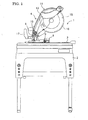
- FIG. 1 is an overall view showing an example of a flip over saw and Fig. 2 is a plain view thereof.
- a flip over saw 1 has a base 2 which is a mounting in rectangular shape in a plain view and a table 3 placed on the base 2, and a saw blade unit 4 mounted on the table 3.
- the table 3 is held rotatable 180 degrees around the rotating shafts 5, 5 extending in the lateral direction (in Figs. 1 and 2 , the right is forward).
- the table 3 can be secured in a horizontal state by a stopper mechanism 6 even if either one or the other surface of table 3 faces upwardly.
- the table 3 also has a circular turntable 7 which is horizontally turnable, and a guide fence 8 parallel to the rotating shaft 5 so as to transverse on the turntable 7.
- the saw blade unit 4 has a support arm 9 standing at the rear part of the turntable 7 and a main body 11 held to be movable up and down by a support shaft 10 at the upper end of the support arm 9.
- a blade cover 12 which is a housing of the main body 11
- a motor 13 and a handle 14 are provided at the left side of a blade cover 12 which is a housing of the main body 11.
- a circular saw blade 15 driven to rotate by the motor 13 is provided.
- the main body 11 is urged toward the top dead center as shown in Fig. 1 by a torsion spring (not shown) provided on the support shaft 10.
- a torsion spring not shown
- the main body 11 is lowered to the bottom dead center where it penetrates a slit (not shown) provided at the center of the turntable 7 when a handle 14 is held down.
- the reference number 16 denotes a safety cover which is at the position of covering the saw blade 15 when the main body 11 is at the top dead center and rotated to expose the saw blade 15 in accordance with lowering of the main body 11.
- the support arm 9 can be tilted with the main body 11 in the right direction (the lower direction of Fig. 2 ) on the turntable 7. Fixing the tilted support arm 9 and the main body 11 by a lever 17 at an arbitrary tilting position provides the saw blade 15 with an angle in the perpendicular direction. With the tilt of the main body 11, bevel cutting can be conducted with respect to the workpiece on the turntable 7. Moreover, the turntable 7 can turn in a horizontal direction with the main body 11 when a handle 14 is held down. In accordance with the selected angle of the horizontal turn of the turntable 7, orthogonal cutting and miter cutting can be conducted. In the orthogonal cutting, the saw blade 15 is perpendicular to the guide fence 8. On the other hand, in the miter cutting the saw blade 15 is horizontally slanted from the perpendicular position.
- the main body 11 can be secured at the bottom dead center as shown in Fig. 3 by means of a locking mechanism 18 provided between the support arm 9 and the main body 11.
- a table saw mode can be obtained wherein only the saw blade 15 protrudes above the table 3 on which a workpiece is slid for cutting.
- the rotating shaft 5 corresponds to the center of rotation of the table 3.
- L1 is defined as the distance between the center of axle O of the rotating shaft 5 and the center O1 of the motor 13
- L2 is defined as the distance between the center of axle O of the rotating shaft 5 and the center 02 of the support shaft 10. Then, L1 is set to be shorter than L2.
- the rotating shafts 5, 5 of the table 3 are positioned on the table 3, so that there is a difference in height of the table 3 between at the first rotating position as shown in Figs. 1-3 (the miter saw mode) and at the second rotating position as shown in Fig. 4 (the table saw mode). (The table 3 in the table saw mode is higher.)
- an opening 19 is provided at the center of the base 2 in the longitudinal direction.
- a pair of first stopper rubbers 20, 20 which support the lower surface of the table 3 at the first rotating position are provided on the front side of the opening 19.
- a pair of second stopper rubbers 21, 21 are provided on the rear side of the opening 19. The second stopper rubbers 21, 21 are positioned on the table 3 at the first rotating position, and support the lower surface of the table 3 at the second rotating position.
- the table 3 can be reversed only in the direction where the front part of the table is flipped up (the direction of an arrow in Fig. 3 ) in converting from the miter saw mode to the table saw mode.
- the table 3 can be reversed only in the direction in which the rear part of the table is flipped up (the direction of an arrow of Fig. 4 ) in converting from the table saw mode to the miter saw mode.
- the rotating shafts 5, 5 are not positioned at the center of the table 3 in the longitudinal direction, but instead at a slightly rearward position in the first rotating position, so that the table 3 does not interfere with the first stopper rubbers 20, 20 upon conversion from the miter saw mode to the table saw mode.
- a motor 13 is located adjacent to the upper side of the rotating shafts 5, 5 of the table 3 with the main body being at the top dead center in a miter saw mode where the main body 11 is positioned above the table.
- the motor's location adjacent to the upper side of the rotating shafts 5, 5 is achieved as follows.
- the center O1 of the motor 13 is located at the area slightly forward from the vertical surface S penetrating the center of axle O of the rotating shafts 5, 5 of the table 3. Then, the horizontal distance H between the center O1 and the vertical surface S is set to be smaller.
- the table 3 is secured by means of a stopper mechanism 6 with the saw blade unit 4 raised as shown in Figs. 1-3 . Then the handle 14 is held to lower the main body 11 in which the blade saw 15 is rotating, so that a workpiece disposed on the turntable 7 can be cut, specifically, the bevel cutting by tilting the main body 11 and the miter cutting by horizontally turning the turntable 7 are achieved.
- the center of gravity of the main body 11 is substantially positioned at the center of the table 3 in the longitudinal direction (that is, adjacent to the rotating shaft 5). Therefore, the accidental reverse of the table 3 can be prevented even if the stopper mechanism 6 is released by malfunction and so on.
- conversion into the table saw mode is conducted as follows. First, the main body 11 is lowered to the bottom dead center to be secured by the locking mechanism 18. Then the stopper mechanism 6 is released and the table 3 is turned 180 degrees in the direction where the front part of the table is flipped up until the table 3 is stopped at the reverse position abutting the second stopper rubbers 21, 21. Likewise, upon conversion into the miter saw mode, the table 3 is turned 180 degrees in the direction where the rear part of the table is flipped up until the table 3 is stopped at the reverse position abutting the first stopper rubbers 20, 20. In these reverse operations, the motor 13 of the main body 11 locked at the bottom dead center is further closer to the rotating shaft 5 in addition to above-described location. Consequently, the moment of inertia upon reversing becomes smaller, so that the reverse can be conducted easily with a light pressure.
- the table 3 Since the table 3 is well-balanced even in the miter saw mode, the table 3 is protected from reversing even if the stopper mechanism 6 is released by malfunction. As a result, damage to the table 3 and the main body 11 caused by accidental reverse can be prevented. In addition, since the center of gravity is closer to the center of rotation, reverse operation of the table 3 becomes easier, thereby improving operability.
- the structure of the flip over saw is not limited to the above embodiments.
- the main body capable of tilting to both sides may be applicable to the present invention, and on the contrary, the structure excluding bevel cutting or miter cutting may also be applicable.
Landscapes
- Life Sciences & Earth Sciences (AREA)
- Engineering & Computer Science (AREA)
- Mechanical Engineering (AREA)
- Wood Science & Technology (AREA)
- Forests & Forestry (AREA)
- Sawing (AREA)
Claims (12)
- Schwenkbare Tischsäge, enthaltend:eine Basis (2);einen horizontalen Tisch (3), der um 180 Grad drehbar der auf der Basis (2) gehalten wird;einen Hauptkörper (11), der durch einen Stützarm (9) gehalten wird, der auf einer Seite des Tischs (3) vorgesehen ist, und der ein Sägeblatt (15) aufweist, das von einem Motor (13) zur Drehung angetrieben wird, undeinen Sperrmechanismus (18), der zwischen dem Hauptkörper (11) und dem Stützarm (9) vorgesehen ist, und der in der Lage ist, den Hauptkörper (11) am unteren Totpunkt zu sperren, an dem das Sägeblatt (15) den Tisch (3) durchdringt,wobei die schwenkbare Tischsäge als eine Gehrungssäge verwendet werden kann, bei der das Sägeblatt (15) ein Werkstück auf dem Tisch (3) schneidet, indem der Hauptkörper (11) abgesenkt wird, wenn sich der Tisch in der ersten Drehposition befindet, in der sich der Hauptkörper (11) über dem Tisch (3) befindet,und wobei die schwenkbare Tischsäge als eine Tischsäge verwendet werden kann, bei der ein Werkstück bezüglich zum Sägeblatt (15) bewegt wird, das nach oben hervorragt, wobei es den Tisch (3) durchdringt, wenn sich der Tisch (3) in der zweiten Drehposition befindet, in der der Hauptkörper (11), der durch den Sperrmechanismus (18) am unteren Totpunkt gesperrt ist, sich unter dem Tisch (3) befindet, wobei sich der Motor (13) direkt über dem Drehzentrum (5) des Tischs (3) oder daneben befindet, wobei sich der Hauptkörper (11) am oberen Totpunkt befindet, wenn sich der Tisch (3) in der ersten Drehposition befindet;dadurch gekennzeichnet, dasssich das Zentrum des Motors (13) vor dem Drehzentrum (5) des Tischs (3) befindet, wobei sich der Hauptkörper (11) am oberen Totpunkt befindet, wenn sich der Tisch (3) in der ersten Drehposition befindet.
- Schwenkbare Tischsäge nach Anspruch 1, dadurch gekennzeichnet, dass der Tisch (3) in der Richtung herumgedreht wird, in der der vordere Teil des Tischs (3) beim Herumdrehen von der ersten Drehposition zur zweiten Drehposition nach oben geklappt wird.
- Schwenkbare Tischsäge nach einem der Ansprüche 1 bis 2, dadurch gekennzeichnet, dass der Hauptkörper (11) durch einen Halterungsschaft (10), der mit einem Stützarm (9) versehen ist, der auf dem Tisch (3) steht, nach oben und unten bewegbar gehalten ist.
- Schwenkbare Tischsäge nach Anspruch 3, dadurch gekennzeichnet, dass der Abstand zwischen dem Drehzentrum (5) des Tischs (3) und dem Zentrum des Motors (13) kürzer ist als der zwischen dem Drehzentrum (5) des Tischs (3) und dem Zentrum des Halterungsschafts (10),
wobei sich der Hauptkörper (11) an einem unteren Totpunkt befindet, wenn sich der Tisch (3) in der ersten Drehposition befindet. - Schwenkbare Tischsäge nach einem der Ansprüche 1 bis 4, dadurch gekennzeichnet, dass sich der Motor (13) auf der einen Seite des Sägeblatts (15) befindet, das auf der oberen Seite des Hauptkörpers (11) positioniert ist.
- Schwenkbare Tischsäge nach einem der Ansprüche 1 bis 5, dadurch gekennzeichnet, dass sich das Drehzentrum (5) des Tischs (3) hinten befindet, wenn sich der Tisch (3) in der ersten Drehposition befindet, wobei der Tisch (3) in der ersten Drehposition durch einen ersten Stopper (20) gestützt wird, der in seitliche Innenflächen an der Vorderseite einer Öffnung (19) der Basis (2) ragt, und wobei der Tisch (3) in der zweiten Drehposition durch einen zweiten Stopper (21) gestützt wird, der in die seitlichen Innenflächen an der Rückseite der Öffnung (19) der Basis (2) ragt.
- Schwenkbare Tischsäge nach Anspruch 8, dadurch gekennzeichnet, dass sich das Drehzentrum (5) des Tischs (3) an der ersten Drehposition auf dem Tisch befindet, so dass der Tisch (3) an der zweiten Drehposition höher ist als an der ersten Drehposition.
- Schwenkbare Tischsäge nach einem der Ansprüche 1 bis 7, dadurch gekennzeichnet, dass ein Vorspannmittel vorgesehen ist, das den Hauptkörper (11) zum oberen Totpunkt drängt.
- Schwenkbare Tischsäge nach einem der Ansprüche 1 bis 8, dadurch gekennzeichnet, dass der Tisch (3) einen Drehtisch (7) aufweist, der sich horizontal drehen kann, und auf dem der Hauptkörper (11) vorgesehen ist, wobei Gehrungssägen in Übereinstimmung mit dem ausgewählten Winkel der horizontalen Drehung des Drehtischs (7) durchgeführt wird, wenn die schwenkbare Tischsäge als Gehrungssäge verwendet wird.
- Schwenkbare Tischsäge nach einem der Ansprüche 1 bis 9, dadurch gekennzeichnet, dass der Hauptkörper (11) zur rechten und linken Seite geneigt werden kann und durch einen Hebel (17) in einer beliebigen Neigungsposition fixiert werden kann, wodurch Schrägschneiden in Übereinstimmung mit dem ausgewählten Winkel senkrecht zum Sägeblatt (4) durchgeführt wird, wenn die schwenkbare Tischsäge als Gehrungssäge verwendet wird.
- Schwenkbare Tischsäge nach Anspruch 9 oder 10, dadurch gekennzeichnet, dass auf dem Tisch (3) ein Führungsgitter (8) parallel zur Drehachse (5) des Tischs (3) vorgesehen ist, so dass es schräg auf dem Drehtisch (7) verläuft.
- Schwenkbare Tischsäge nach einem der Ansprüche 1 bis 11, dadurch gekennzeichnet, dass der Hauptkörper (11) mit einem Handgriff (14) versehen ist, durch den der Hauptkörper (11) auf der Seite, auf der sich der Motor (13) befindet, nach oben und unten bewegt werden kann.
Applications Claiming Priority (1)
| Application Number | Priority Date | Filing Date | Title |
|---|---|---|---|
| JP2004228424A JP2006044070A (ja) | 2004-08-04 | 2004-08-04 | フリップオーバーソー |
Publications (2)
| Publication Number | Publication Date |
|---|---|
| EP1623802A1 EP1623802A1 (de) | 2006-02-08 |
| EP1623802B1 true EP1623802B1 (de) | 2008-10-08 |
Family
ID=35057056
Family Applications (1)
| Application Number | Title | Priority Date | Filing Date |
|---|---|---|---|
| EP05016704A Expired - Lifetime EP1623802B1 (de) | 2004-08-04 | 2005-08-01 | Eine zwischen einer Übertisch- und einer Untertischlage verschwenkbare Säge |
Country Status (5)
| Country | Link |
|---|---|
| EP (1) | EP1623802B1 (de) |
| JP (1) | JP2006044070A (de) |
| CN (1) | CN100384577C (de) |
| AT (1) | ATE410278T1 (de) |
| DE (2) | DE602005010158D1 (de) |
Families Citing this family (3)
| Publication number | Priority date | Publication date | Assignee | Title |
|---|---|---|---|---|
| GB0606846D0 (en) * | 2006-04-05 | 2006-05-17 | Black & Decker Inc | A Flip Over Saw |
| CN101284318A (zh) * | 2007-04-10 | 2008-10-15 | 张建江 | 复合台锯机头翻转结构 |
| CN110014190B (zh) * | 2012-07-13 | 2021-09-07 | 苏州宝时得电动工具有限公司 | 便携式切割机 |
Family Cites Families (8)
| Publication number | Priority date | Publication date | Assignee | Title |
|---|---|---|---|---|
| US3570564A (en) * | 1968-01-03 | 1971-03-16 | Lutz Kg Maschf Eugen | Convertible circular bench saw and mitering saw |
| DE7621408U1 (de) * | 1976-07-07 | 1977-12-29 | Gotthold Haffner Gmbh + Co, 7136 Oetisheim | Werkstuecktisch zum wechselweisen anbau einer handkreissaege als tischsaege oder als kappsaege |
| DE3106098A1 (de) | 1981-02-19 | 1982-09-02 | Eugen Lutz GmbH u. Co Maschinenfabrik, 7130 Mühlacker | Kombinierte tisch- und gehrungssaege |
| DE3134086C2 (de) * | 1981-08-28 | 1984-10-25 | Festo-Maschinenfabrik Gottlieb Stoll, 7300 Esslingen | Kreissäge |
| DE8632048U1 (de) * | 1986-11-29 | 1987-01-22 | Eugen Lutz GmbH u. Co Maschinenfabrik, 7130 Mühlacker | Werkstücktisch zum Anbau von Handkreissägen |
| DE4106635C1 (de) * | 1991-02-28 | 1992-07-23 | Black & Decker Inc., Newark, Del., Us | |
| GB9218363D0 (en) * | 1992-08-28 | 1992-10-14 | Black & Decker Inc | Pivoting power tool with table |
| GB9314163D0 (en) * | 1993-07-08 | 1993-08-18 | Black & Decker Inc | Chop/table saw arrangement |
-
2004
- 2004-08-04 JP JP2004228424A patent/JP2006044070A/ja active Pending
-
2005
- 2005-07-20 CN CNB2005100850825A patent/CN100384577C/zh not_active Expired - Lifetime
- 2005-08-01 DE DE602005010158T patent/DE602005010158D1/de not_active Expired - Lifetime
- 2005-08-01 EP EP05016704A patent/EP1623802B1/de not_active Expired - Lifetime
- 2005-08-01 AT AT05016704T patent/ATE410278T1/de not_active IP Right Cessation
- 2005-08-01 DE DE202005021523U patent/DE202005021523U1/de not_active Expired - Lifetime
Also Published As
| Publication number | Publication date |
|---|---|
| EP1623802A1 (de) | 2006-02-08 |
| DE602005010158D1 (de) | 2008-11-20 |
| CN100384577C (zh) | 2008-04-30 |
| DE202005021523U1 (de) | 2008-06-12 |
| JP2006044070A (ja) | 2006-02-16 |
| ATE410278T1 (de) | 2008-10-15 |
| CN1733406A (zh) | 2006-02-15 |
Similar Documents
| Publication | Publication Date | Title |
|---|---|---|
| EP1842613B1 (de) | Umschwenkbare Säge | |
| US20170341261A1 (en) | Table cutting machine | |
| EP2580034B1 (de) | Verriegelungskonstruktion für eine gehrungssäge mit linearem führungsmechanismus mit drehgelenk | |
| US20080209739A1 (en) | Power tool with chips ejecting mechanism | |
| EP1614511B1 (de) | Schutzabdeckung für eine Säge | |
| US20130269497A1 (en) | Table saws | |
| US20090235796A1 (en) | Table cutting machine | |
| JP2010149457A (ja) | 携帯用切断機 | |
| EP2436494B1 (de) | Schneidemaschine mit einer Schutzanordnung | |
| EP1621302B1 (de) | Anschlag für Gehrungssägen | |
| US20070214928A1 (en) | Miter Saw | |
| JP3698954B2 (ja) | 携帯用動力切断機 | |
| EP1623802A1 (de) | Eine zwischen einer Übertisch- und einer Untertischlage verschwenkbare Säge | |
| JP2001269901A (ja) | 携帯用動力切断機 | |
| JP5439868B2 (ja) | 携帯用切断機 | |
| EP1623801B9 (de) | Eine zwischen einer Übertisch- und einer Untertischlage verschwenkbare Säge | |
| US20060101967A1 (en) | Greater capacity cutting saw | |
| EP1623800A1 (de) | Tischverriegelungsvorrichtung für Sägen | |
| JP5507983B2 (ja) | 丸鋸 | |
| JP3580742B2 (ja) | 切粉遮蔽機能付き携帯用電気マルノコ | |
| JP2007118383A (ja) | 切断機 | |
| JP2004330618A (ja) | 卓上丸鋸 | |
| CN116329651A (zh) | 便携式切割机 | |
| JP2024134437A (ja) | 携帯用切断機 | |
| JP2004330619A (ja) | 上部テーブル付卓上丸鋸 |
Legal Events
| Date | Code | Title | Description |
|---|---|---|---|
| PUAI | Public reference made under article 153(3) epc to a published international application that has entered the european phase |
Free format text: ORIGINAL CODE: 0009012 |
|
| AK | Designated contracting states |
Kind code of ref document: A1 Designated state(s): AT BE BG CH CY CZ DE DK EE ES FI FR GB GR HU IE IS IT LI LT LU LV MC NL PL PT RO SE SI SK TR |
|
| AX | Request for extension of the european patent |
Extension state: AL BA HR MK YU |
|
| 17P | Request for examination filed |
Effective date: 20060331 |
|
| AKX | Designation fees paid |
Designated state(s): DE GB IT NL SE |
|
| RBV | Designated contracting states (corrected) |
Designated state(s): AT BE BG CH CY CZ DE DK EE ES FI FR GB GR HU IE IS IT LI LT LU LV MC NL PL PT RO SE SI SK TR |
|
| GRAP | Despatch of communication of intention to grant a patent |
Free format text: ORIGINAL CODE: EPIDOSNIGR1 |
|
| GRAS | Grant fee paid |
Free format text: ORIGINAL CODE: EPIDOSNIGR3 |
|
| GRAA | (expected) grant |
Free format text: ORIGINAL CODE: 0009210 |
|
| AK | Designated contracting states |
Kind code of ref document: B1 Designated state(s): AT BE BG CH CY CZ DE DK EE ES FI FR GB GR HU IE IS IT LI LT LU LV MC NL PL PT RO SE SI SK TR |
|
| REG | Reference to a national code |
Ref country code: GB Ref legal event code: FG4D |
|
| REG | Reference to a national code |
Ref country code: CH Ref legal event code: EP |
|
| REG | Reference to a national code |
Ref country code: IE Ref legal event code: FG4D |
|
| REF | Corresponds to: |
Ref document number: 602005010158 Country of ref document: DE Date of ref document: 20081120 Kind code of ref document: P |
|
| REG | Reference to a national code |
Ref country code: SE Ref legal event code: TRGR |
|
| PG25 | Lapsed in a contracting state [announced via postgrant information from national office to epo] |
Ref country code: SI Free format text: LAPSE BECAUSE OF FAILURE TO SUBMIT A TRANSLATION OF THE DESCRIPTION OR TO PAY THE FEE WITHIN THE PRESCRIBED TIME-LIMIT Effective date: 20081008 |
|
| PG25 | Lapsed in a contracting state [announced via postgrant information from national office to epo] |
Ref country code: LT Free format text: LAPSE BECAUSE OF FAILURE TO SUBMIT A TRANSLATION OF THE DESCRIPTION OR TO PAY THE FEE WITHIN THE PRESCRIBED TIME-LIMIT Effective date: 20081008 Ref country code: ES Free format text: LAPSE BECAUSE OF FAILURE TO SUBMIT A TRANSLATION OF THE DESCRIPTION OR TO PAY THE FEE WITHIN THE PRESCRIBED TIME-LIMIT Effective date: 20090119 Ref country code: BG Free format text: LAPSE BECAUSE OF FAILURE TO SUBMIT A TRANSLATION OF THE DESCRIPTION OR TO PAY THE FEE WITHIN THE PRESCRIBED TIME-LIMIT Effective date: 20090108 Ref country code: AT Free format text: LAPSE BECAUSE OF FAILURE TO SUBMIT A TRANSLATION OF THE DESCRIPTION OR TO PAY THE FEE WITHIN THE PRESCRIBED TIME-LIMIT Effective date: 20081008 |
|
| PG25 | Lapsed in a contracting state [announced via postgrant information from national office to epo] |
Ref country code: IS Free format text: LAPSE BECAUSE OF FAILURE TO SUBMIT A TRANSLATION OF THE DESCRIPTION OR TO PAY THE FEE WITHIN THE PRESCRIBED TIME-LIMIT Effective date: 20090208 Ref country code: PT Free format text: LAPSE BECAUSE OF FAILURE TO SUBMIT A TRANSLATION OF THE DESCRIPTION OR TO PAY THE FEE WITHIN THE PRESCRIBED TIME-LIMIT Effective date: 20090218 Ref country code: FI Free format text: LAPSE BECAUSE OF FAILURE TO SUBMIT A TRANSLATION OF THE DESCRIPTION OR TO PAY THE FEE WITHIN THE PRESCRIBED TIME-LIMIT Effective date: 20081008 Ref country code: LV Free format text: LAPSE BECAUSE OF FAILURE TO SUBMIT A TRANSLATION OF THE DESCRIPTION OR TO PAY THE FEE WITHIN THE PRESCRIBED TIME-LIMIT Effective date: 20081008 Ref country code: PL Free format text: LAPSE BECAUSE OF FAILURE TO SUBMIT A TRANSLATION OF THE DESCRIPTION OR TO PAY THE FEE WITHIN THE PRESCRIBED TIME-LIMIT Effective date: 20081008 |
|
| PG25 | Lapsed in a contracting state [announced via postgrant information from national office to epo] |
Ref country code: EE Free format text: LAPSE BECAUSE OF FAILURE TO SUBMIT A TRANSLATION OF THE DESCRIPTION OR TO PAY THE FEE WITHIN THE PRESCRIBED TIME-LIMIT Effective date: 20081008 Ref country code: BE Free format text: LAPSE BECAUSE OF FAILURE TO SUBMIT A TRANSLATION OF THE DESCRIPTION OR TO PAY THE FEE WITHIN THE PRESCRIBED TIME-LIMIT Effective date: 20081008 Ref country code: DK Free format text: LAPSE BECAUSE OF FAILURE TO SUBMIT A TRANSLATION OF THE DESCRIPTION OR TO PAY THE FEE WITHIN THE PRESCRIBED TIME-LIMIT Effective date: 20081008 Ref country code: RO Free format text: LAPSE BECAUSE OF FAILURE TO SUBMIT A TRANSLATION OF THE DESCRIPTION OR TO PAY THE FEE WITHIN THE PRESCRIBED TIME-LIMIT Effective date: 20081008 |
|
| PLBE | No opposition filed within time limit |
Free format text: ORIGINAL CODE: 0009261 |
|
| STAA | Information on the status of an ep patent application or granted ep patent |
Free format text: STATUS: NO OPPOSITION FILED WITHIN TIME LIMIT |
|
| PG25 | Lapsed in a contracting state [announced via postgrant information from national office to epo] |
Ref country code: CZ Free format text: LAPSE BECAUSE OF FAILURE TO SUBMIT A TRANSLATION OF THE DESCRIPTION OR TO PAY THE FEE WITHIN THE PRESCRIBED TIME-LIMIT Effective date: 20081008 Ref country code: IT Free format text: LAPSE BECAUSE OF FAILURE TO SUBMIT A TRANSLATION OF THE DESCRIPTION OR TO PAY THE FEE WITHIN THE PRESCRIBED TIME-LIMIT Effective date: 20081008 |
|
| 26N | No opposition filed |
Effective date: 20090709 |
|
| PG25 | Lapsed in a contracting state [announced via postgrant information from national office to epo] |
Ref country code: SK Free format text: LAPSE BECAUSE OF FAILURE TO SUBMIT A TRANSLATION OF THE DESCRIPTION OR TO PAY THE FEE WITHIN THE PRESCRIBED TIME-LIMIT Effective date: 20081008 |
|
| PG25 | Lapsed in a contracting state [announced via postgrant information from national office to epo] |
Ref country code: MC Free format text: LAPSE BECAUSE OF NON-PAYMENT OF DUE FEES Effective date: 20090831 |
|
| REG | Reference to a national code |
Ref country code: CH Ref legal event code: PL |
|
| PG25 | Lapsed in a contracting state [announced via postgrant information from national office to epo] |
Ref country code: LI Free format text: LAPSE BECAUSE OF NON-PAYMENT OF DUE FEES Effective date: 20090831 Ref country code: CH Free format text: LAPSE BECAUSE OF NON-PAYMENT OF DUE FEES Effective date: 20090831 |
|
| REG | Reference to a national code |
Ref country code: IE Ref legal event code: MM4A |
|
| PG25 | Lapsed in a contracting state [announced via postgrant information from national office to epo] |
Ref country code: IE Free format text: LAPSE BECAUSE OF NON-PAYMENT OF DUE FEES Effective date: 20090801 |
|
| PG25 | Lapsed in a contracting state [announced via postgrant information from national office to epo] |
Ref country code: GR Free format text: LAPSE BECAUSE OF FAILURE TO SUBMIT A TRANSLATION OF THE DESCRIPTION OR TO PAY THE FEE WITHIN THE PRESCRIBED TIME-LIMIT Effective date: 20090109 |
|
| PG25 | Lapsed in a contracting state [announced via postgrant information from national office to epo] |
Ref country code: LU Free format text: LAPSE BECAUSE OF NON-PAYMENT OF DUE FEES Effective date: 20090801 |
|
| PG25 | Lapsed in a contracting state [announced via postgrant information from national office to epo] |
Ref country code: HU Free format text: LAPSE BECAUSE OF FAILURE TO SUBMIT A TRANSLATION OF THE DESCRIPTION OR TO PAY THE FEE WITHIN THE PRESCRIBED TIME-LIMIT Effective date: 20090409 |
|
| PG25 | Lapsed in a contracting state [announced via postgrant information from national office to epo] |
Ref country code: TR Free format text: LAPSE BECAUSE OF FAILURE TO SUBMIT A TRANSLATION OF THE DESCRIPTION OR TO PAY THE FEE WITHIN THE PRESCRIBED TIME-LIMIT Effective date: 20081008 |
|
| PG25 | Lapsed in a contracting state [announced via postgrant information from national office to epo] |
Ref country code: CY Free format text: LAPSE BECAUSE OF FAILURE TO SUBMIT A TRANSLATION OF THE DESCRIPTION OR TO PAY THE FEE WITHIN THE PRESCRIBED TIME-LIMIT Effective date: 20081008 |
|
| REG | Reference to a national code |
Ref country code: FR Ref legal event code: PLFP Year of fee payment: 12 |
|
| REG | Reference to a national code |
Ref country code: FR Ref legal event code: PLFP Year of fee payment: 13 |
|
| REG | Reference to a national code |
Ref country code: FR Ref legal event code: PLFP Year of fee payment: 14 |
|
| PGFP | Annual fee paid to national office [announced via postgrant information from national office to epo] |
Ref country code: GB Payment date: 20240627 Year of fee payment: 20 |
|
| PGFP | Annual fee paid to national office [announced via postgrant information from national office to epo] |
Ref country code: NL Payment date: 20240705 Year of fee payment: 20 |
|
| PGFP | Annual fee paid to national office [announced via postgrant information from national office to epo] |
Ref country code: DE Payment date: 20240702 Year of fee payment: 20 |
|
| PGFP | Annual fee paid to national office [announced via postgrant information from national office to epo] |
Ref country code: FR Payment date: 20240702 Year of fee payment: 20 |
|
| PGFP | Annual fee paid to national office [announced via postgrant information from national office to epo] |
Ref country code: SE Payment date: 20240702 Year of fee payment: 20 |
|
| REG | Reference to a national code |
Ref country code: DE Ref legal event code: R071 Ref document number: 602005010158 Country of ref document: DE |
|
| REG | Reference to a national code |
Ref country code: NL Ref legal event code: MK Effective date: 20250731 |
|
| REG | Reference to a national code |
Ref country code: GB Ref legal event code: PE20 Expiry date: 20250731 |
|
| REG | Reference to a national code |
Ref country code: SE Ref legal event code: EUG |