EP1623918B2 - Dispositif de réglage pour changement de vitesse - Google Patents
Dispositif de réglage pour changement de vitesse Download PDFInfo
- Publication number
- EP1623918B2 EP1623918B2 EP05016841.8A EP05016841A EP1623918B2 EP 1623918 B2 EP1623918 B2 EP 1623918B2 EP 05016841 A EP05016841 A EP 05016841A EP 1623918 B2 EP1623918 B2 EP 1623918B2
- Authority
- EP
- European Patent Office
- Prior art keywords
- lever
- shifter
- clamp
- handlebar
- screw
- Prior art date
- Legal status (The legal status is an assumption and is not a legal conclusion. Google has not performed a legal analysis and makes no representation as to the accuracy of the status listed.)
- Expired - Lifetime
Links
Images


Classifications
-
- B—PERFORMING OPERATIONS; TRANSPORTING
- B62—LAND VEHICLES FOR TRAVELLING OTHERWISE THAN ON RAILS
- B62K—CYCLES; CYCLE FRAMES; CYCLE STEERING DEVICES; RIDER-OPERATED TERMINAL CONTROLS SPECIALLY ADAPTED FOR CYCLES; CYCLE AXLE SUSPENSIONS; CYCLE SIDECARS, FORECARS, OR THE LIKE
- B62K23/00—Rider-operated controls specially adapted for cycles, i.e. means for initiating control operations, e.g. levers, grips
- B62K23/02—Rider-operated controls specially adapted for cycles, i.e. means for initiating control operations, e.g. levers, grips hand actuated
- B62K23/06—Levers
-
- B—PERFORMING OPERATIONS; TRANSPORTING
- B62—LAND VEHICLES FOR TRAVELLING OTHERWISE THAN ON RAILS
- B62K—CYCLES; CYCLE FRAMES; CYCLE STEERING DEVICES; RIDER-OPERATED TERMINAL CONTROLS SPECIALLY ADAPTED FOR CYCLES; CYCLE AXLE SUSPENSIONS; CYCLE SIDECARS, FORECARS, OR THE LIKE
- B62K19/00—Cycle frames
- B62K19/30—Frame parts shaped to receive other cycle parts or accessories
-
- B—PERFORMING OPERATIONS; TRANSPORTING
- B62—LAND VEHICLES FOR TRAVELLING OTHERWISE THAN ON RAILS
- B62M—RIDER PROPULSION OF WHEELED VEHICLES OR SLEDGES; POWERED PROPULSION OF SLEDGES OR SINGLE-TRACK CYCLES; TRANSMISSIONS SPECIALLY ADAPTED FOR SUCH VEHICLES
- B62M25/00—Actuators for gearing speed-change mechanisms specially adapted for cycles
- B62M25/02—Actuators for gearing speed-change mechanisms specially adapted for cycles with mechanical transmitting systems, e.g. cables, levers
- B62M25/04—Actuators for gearing speed-change mechanisms specially adapted for cycles with mechanical transmitting systems, e.g. cables, levers hand actuated
-
- Y—GENERAL TAGGING OF NEW TECHNOLOGICAL DEVELOPMENTS; GENERAL TAGGING OF CROSS-SECTIONAL TECHNOLOGIES SPANNING OVER SEVERAL SECTIONS OF THE IPC; TECHNICAL SUBJECTS COVERED BY FORMER USPC CROSS-REFERENCE ART COLLECTIONS [XRACs] AND DIGESTS
- Y10—TECHNICAL SUBJECTS COVERED BY FORMER USPC
- Y10T—TECHNICAL SUBJECTS COVERED BY FORMER US CLASSIFICATION
- Y10T74/00—Machine element or mechanism
- Y10T74/20—Control lever and linkage systems
- Y10T74/20396—Hand operated
- Y10T74/20402—Flexible transmitter [e.g., Bowden cable]
- Y10T74/2042—Flexible transmitter [e.g., Bowden cable] and hand operator
- Y10T74/20438—Single rotatable lever [e.g., for bicycle brake or derailleur]
Definitions
- the invention relates to a switch for actuating a transmission on a bicycle, according to the preamble of claims 1 and 6.
- a switch is known with two levers which are pivotally mounted on a bearing block.
- the bearing block is firmly bolted to a clamp attachable to the bicycle frame.
- the two shift levers are each connected to a shift cable to switch a front derailleur front or rear derailleur either can. Friction discs hold the shifter in the desired pivot position.
- a switch with the features of claim 1 which has a variety of individual settings so as to meet the wishes of all users as possible.
- This switch allows the rider of the bicycle to tune the actuating surface with a contact surface on the release lever, taking into account that it rotates about an axis in a plane of rotation which is inclined by an angle of about 60 ° to that of the clamping lever and that Actuating surface as well as the contact surface with the thumb are to use.
- the direction of actuation of the contact surface like that of the actuating surface, points in the direction of travel, but faces upwards.
- the attachment of the clamping lever on the driving part is preferably done via two clamping arms which surround the driving part and a clamping screw which connects the clamping arms and braced against each other.
- the clamping screw preferably has a shaft which rests in an annular recess of the driving part left and right on two flanks and thus secures the axial position of the clamping lever on the driving part.
- a switch with the features of claim 6 is proposed.
- the variable attachment of a clamp on the switch housing causes the clamp of the switch housing can be mounted either directly next to the handle on the handlebar, or only after a brake bandage of the hand brake lever, the clamp is changeable in position on the switch housing.
- the invention has therefore set itself the task of creating a switch on the handlebar for switching gears in a bicycle transmission, which has a clamping lever and a release lever, regardless of the structural design of the handlebar with a brake lever and the brake bandage according to the individual requirements the driver can be operated optimally ergonomically.
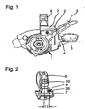
- 1 denotes a switch housing, then this is connected by means of a clamp 6 with a handlebar 8 and has this with a cable storage associated driving part 14, with which a clamping lever 2 is connected to an actuating surface 3.
- the tensioning lever 2 has a first clamping arm 12 and a second clamping arm 13, which can be placed around a cylindrical outer surface 19 on the driving part 14 and can be connected to each other by a clamping screw 15.
- the clamping screw 15 has a shank 16 which, when the clamping lever 2 is mounted correctly, engages in an annular recess 17 with two flanks 18 on the outer surface 19 of the driving part 14, whereby a frictional engagement between the clamping lever 2 and the driving part 14 is produced.
- the tensioning lever 2 is actuated in a plane of rotation 25 perpendicular to the plane of rotation 20, winds the rope in a direction Seilaufwickeldreicardi 23 on the cable storage and thus switches gradually the individual stages of the transmission in a first switching direction.
- This release lever 4 rotates in a plane that is inclined to the plane of rotation 20 of the clamping lever 2 by an angle 22 of 60 ° upwards, so that the serving driver actually inclined to the direction of movement on the clamping lever 2 by 60 ° upwards in the direction of travel would have to make movement in an actuating direction 21. Since the release lever 4 but only to release the rope in a Seiluzagabefrontrion 24 needs a small push, the thumb movement goes into the void when the first contact is made. So the thumb slips off the contact surface 5, when the circuit is done. In this way, to release the rope and to shift the gears counter to the first shift direction, a driver gets used quickly and so leaves the mechanism completely switching.
- the clamp 6 is bolted to a socket 7 on the switch housing 1, wherein the base 7 has a longitudinal guide 26 and at least two holes 9, in which a screw 10 for fixing the clamp. 6 is screwed in.
- the two holes 9 have a distance 11 from each other, which makes it possible to arrange the clamp 6 selectively at one or the offset by this distance 11 other hole 9.
Landscapes
- Engineering & Computer Science (AREA)
- Mechanical Engineering (AREA)
- Chemical & Material Sciences (AREA)
- Combustion & Propulsion (AREA)
- Transportation (AREA)
- Mechanical Control Devices (AREA)
- Steering Devices For Bicycles And Motorcycles (AREA)
- Rotary Switch, Piano Key Switch, And Lever Switch (AREA)
Claims (9)
- Commutateur destiné à actionner une boîte de vitesses sur une bicyclette, comportant un boîtier de commutateur (1), un enrouleur de câble destiné à enrouler un câble pour actionner des vitesses individuelles de la boîte de vitesses, un levier de serrage (2), un levier de libération (4), le levier de serrage (2) sur le boîtier de commutateur (1) pouvant tourner autour d'un axe de rotation (25) pour passer chaque vitesse dans la boîte de vitesses dans un sens de rotation d'enroulement de câble, tandis que dans un sens de rotation de libération de câble respectivement au moins une vitesse peut être passée par l'actionnement du levier de libération (4),
caractérisé en ce que les positions du levier de serrage (2) et du levier de libération (4) sont ajustables l'une par rapport à l'autre et les deux par rapport à une partie de poignée (27) sur le guidon (8) de la bicyclette et
en ce que le levier de serrage (2) peut être aménagé sur un élément d'entraînement (14) relié à l'enrouleur de câble à l'intérieur de son plan de rotation (20) perpendiculaire à l'axe de rotation (25) dans de nombreuses positions quelconques par rapport à l'élément d'entraînement (14). - Commutateur selon la revendication 1,
caractérisé en ce que le levier de serrage (2) est relié par entraînement par friction à une surface extérieure (19) sur l'élément d'entraînement (14). - Commutateur selon la revendication 1 ou 2,
caractérisé en ce que le levier de serrage (2) comprend un premier bras de serrage (12) et un second bras de serrage (13), qui peuvent être reliés de manière solidaire en rotation par une vis de serrage (15) à la surface extérieure (19) sur l'élément d'entraînement (14). - Commutateur selon la revendication 3,
caractérisé en ce que la vis de serrage (15) comprend une tige (16) qui est disposée entre deux flancs (18) d'un évidement (17) de l'élément d'entraînement (14). - Commutateur selon l'une quelconque des revendications 1 à 4,
caractérisé en ce que le levier de serrage (2) peut être bloqué dans chaque position à l'intérieur d'un angle d'au moins 120 degrés. - Commutateur destiné à actionner une boîte de vitesses sur une bicyclette, comportant un boîtier de commutateur (1), un enrouleur de câble destiné à enrouler un câble pour actionner chaque vitesse de la boîte de vitesses, un levier de serrage (2) et un levier de libération (4), le levier de serrage (2) sur le boîtier de commutateur (1) pouvant être amené en rotation dans un sens de rotation d'enroulement de câble pour passer chaque vitesse dans la boîte de vitesses, tandis que dans un sens de rotation de libération du câble, grâce à l'actionnement du levier de libération (4), respectivement au moins une vitesse peut être passée, le boîtier de commutateur (1) étant pourvu d'une bride (6) pouvant être aménagée sur un guidon (8),
caractérisé en ce que la bride (6) est conçue séparément du boîtier de commutateur (1) et est conçue de manière à pouvoir se déplacer par rapport au boîtier de commutateur (1) parallèlement au guidon (8) entre différentes positions d'aménagement sur le boîtier de commutateur (1), en ce que le boîtier de commutateur (1) comprend un socle (7) doté d'au moins deux alésages (9), les alésages (9) étant distants les uns des autres et
en ce que le socle (7) comprend un guidage longitudinal (26) parallèle à la partie de poignée (27) du guidon (8), guidage sur lequel la bride (6) peut être déplacée et fixée à un des alésages (9) au moyen d'une vis (10) sur le guidage longitudinal (26). - Commutateur selon l'une quelconque des revendications 1 ou 6,
caractérisé en ce que le plan de l'actionnement d'une surface de contact (5) du levier de libération (4) est incliné d'approximativement 60° par rapport au plan d'actionnement du levier de serrage (2) avec sa surface d'actionnement (3). - Commutateur selon la revendication 7,
caractérisé en ce que la position de la surface d'actionnement (3) peut être actionnée alternativement respectivement par le pouce de la main située sur la partie de poignée (27) du guidon (8) et la surface de contact (5) l'une par rapport à l'autre peut être optimisée en réglant le levier de serrage (2) sur l'élément d'entraînement (14). - Procédé de réglage d'un commutateur, constitué d'un boîtier de commutateur selon l'une des revendications 3 à 5 et selon l'une des revendications 6 à 8 comprenant une bride (6), un levier de serrage (2) doté d'une surface d'actionnement (3) et un levier de libération (4) doté d'une surface de contact (5),
caractérisé par les étapes de procédé suivantes consistant à :- décider si la bride (6) doit être montée sur le guidon (8) entre la partie de poignée (27) et une garniture de frein (29) ou sur le côté de la garniture de frein (29) opposé à la partie de poignée (27) en tenant compte de la position optimale de la surface de contact (3) par rapport à la position du pouce du conducteur pendant le trajet ;- fixer la bride (6) sur le boîtier de commutateur (1) au moyen de la vis (10), qui est vissée dans l'alésage (9) résultant de la décision ;- pousser la bride (6) avec le boîtier de commutateur (1) sur le guidon (8) ;- pousser la garniture de frein (28) sur le guidon (8) devant ou derrière la bride (6) respectivement en fonction de la décision précédente ;- pousser la partie de poignée (27) ;- pousser le levier de tension (2) sur la partie d'entraînement (14) et fixer sans serrer la vis de serrage (15) dans les bras de serrage (12) et (13) ;- serrer la vis (10) pour fixer le boîtier de commutateur (1) après examen par le conducteur assis sur la bicyclette ;- serrer la vis de serrage (15) après que le conducteur assis sur la bicyclette ait examiné la position de la surface d'actionnement (3) par rapport à la surface de contact (5) ;- essayer de rouler et éventuellement corriger les accouplements de serrage en desserrant et vissant à nouveau la vis (10) et/ou la vis de serrage (15).
Priority Applications (2)
| Application Number | Priority Date | Filing Date | Title |
|---|---|---|---|
| EP08006812A EP1947004B1 (fr) | 2004-08-04 | 2005-08-03 | Dispositif de réglage pour manettes de dérailleur |
| DE202005021561U DE202005021561U1 (de) | 2004-08-04 | 2005-08-03 | Verstelleinrichtung für Triggerschalter |
Applications Claiming Priority (1)
| Application Number | Priority Date | Filing Date | Title |
|---|---|---|---|
| DE102004037741.3A DE102004037741C5 (de) | 2004-08-04 | 2004-08-04 | Triggerschalter zur Betätigung eines Getriebes an einem Fahrrad |
Related Child Applications (2)
| Application Number | Title | Priority Date | Filing Date |
|---|---|---|---|
| EP08006812A Division EP1947004B1 (fr) | 2004-08-04 | 2005-08-03 | Dispositif de réglage pour manettes de dérailleur |
| EP08006812A Division-Into EP1947004B1 (fr) | 2004-08-04 | 2005-08-03 | Dispositif de réglage pour manettes de dérailleur |
Publications (3)
| Publication Number | Publication Date |
|---|---|
| EP1623918A1 EP1623918A1 (fr) | 2006-02-08 |
| EP1623918B1 EP1623918B1 (fr) | 2008-05-21 |
| EP1623918B2 true EP1623918B2 (fr) | 2018-02-14 |
Family
ID=35134081
Family Applications (2)
| Application Number | Title | Priority Date | Filing Date |
|---|---|---|---|
| EP08006812A Revoked EP1947004B1 (fr) | 2004-08-04 | 2005-08-03 | Dispositif de réglage pour manettes de dérailleur |
| EP05016841.8A Expired - Lifetime EP1623918B2 (fr) | 2004-08-04 | 2005-08-03 | Dispositif de réglage pour changement de vitesse |
Family Applications Before (1)
| Application Number | Title | Priority Date | Filing Date |
|---|---|---|---|
| EP08006812A Revoked EP1947004B1 (fr) | 2004-08-04 | 2005-08-03 | Dispositif de réglage pour manettes de dérailleur |
Country Status (4)
| Country | Link |
|---|---|
| US (1) | US9073596B2 (fr) |
| EP (2) | EP1947004B1 (fr) |
| CN (2) | CN100575178C (fr) |
| DE (4) | DE102004037741C5 (fr) |
Cited By (2)
| Publication number | Priority date | Publication date | Assignee | Title |
|---|---|---|---|---|
| US11780529B2 (en) | 2021-09-13 | 2023-10-10 | Shimano Inc. | Operating device for human-powered vehicle |
| US12060131B2 (en) | 2021-09-13 | 2024-08-13 | Shimano Inc. | Operating device for human-powered vehicle |
Families Citing this family (32)
| Publication number | Priority date | Publication date | Assignee | Title |
|---|---|---|---|---|
| DE102004014035A1 (de) * | 2004-03-19 | 2005-10-06 | Sram Deutschland Gmbh | Fahrrad-Gangschaltungseinrichtung |
| DE102004037741C5 (de) | 2004-08-04 | 2019-07-11 | Sram Deutschland Gmbh | Triggerschalter zur Betätigung eines Getriebes an einem Fahrrad |
| US8042427B2 (en) * | 2006-02-16 | 2011-10-25 | Shimano Inc. | Bicycle shifter |
| DE102008048134C5 (de) * | 2008-09-20 | 2018-09-27 | Sram Deutschland Gmbh | Schalter zur Betätigung eines Getriebes an einem Fahrrad |
| US8201476B2 (en) * | 2008-12-09 | 2012-06-19 | Shimano Inc. | Bicycle operating device |
| JP2011136639A (ja) * | 2009-12-28 | 2011-07-14 | Shimano Inc | 自転車用変速操作装置及び自転車用変速操作装置セット |
| US8061667B2 (en) | 2010-04-16 | 2011-11-22 | Sram, Llc | Mounting device for bicycle control components |
| EP2460716B1 (fr) | 2010-12-03 | 2014-05-07 | Campagnolo S.r.l. | Levier de commande et dispositif d'actionnement d'un changement de vitesses de bicyclette au guidon |
| US9033833B2 (en) | 2011-01-28 | 2015-05-19 | Paha Designs, Llc | Gear transmission and derailleur system |
| US10207772B2 (en) | 2011-01-28 | 2019-02-19 | Paha Designs, Llc | Gear transmission and derailleur system |
| US9327792B2 (en) | 2011-01-28 | 2016-05-03 | Paha Designs, Llc | Gear transmission and derailleur system |
| US9440703B2 (en) * | 2011-12-19 | 2016-09-13 | Shimano Inc. | Clamp assembly for fixing handlebar grip |
| US8720301B2 (en) | 2012-02-24 | 2014-05-13 | Shimano Inc. | Bicycle operating device |
| US9132887B2 (en) | 2012-02-24 | 2015-09-15 | Shimano Inc. | Bicycle operating device |
| US8746105B2 (en) | 2012-02-24 | 2014-06-10 | Shimano Inc. | Bicycle operating device |
| US9326412B2 (en) * | 2012-11-16 | 2016-04-26 | Shimano Inc. | Bicycle electric control device |
| US9145183B2 (en) * | 2012-11-16 | 2015-09-29 | Shimano Inc. | Adjustable bicycle electric control device |
| US9079629B2 (en) * | 2012-11-28 | 2015-07-14 | Shimano Inc. | Bicycle electric control device with adjustable switch unit |
| JP2014196060A (ja) | 2013-03-29 | 2014-10-16 | 株式会社シマノ | 操作装置 |
| US9771129B2 (en) * | 2013-06-21 | 2017-09-26 | Shimano (Singapore) Pte. Ltd. | Bicycle control device |
| US9260155B2 (en) * | 2013-08-30 | 2016-02-16 | Sue Knaup | Bicycle shift lever |
| US10137957B2 (en) | 2015-08-06 | 2018-11-27 | Shimano Inc. | Bicycle operating device |
| US10689060B2 (en) * | 2015-10-08 | 2020-06-23 | Shimano Inc. | Bicycle operating device |
| US9932091B2 (en) | 2016-03-25 | 2018-04-03 | Shimano Inc. | Bicycle operating device |
| JP2018052357A (ja) | 2016-09-29 | 2018-04-05 | 株式会社シマノ | 自転車操作装置 |
| JP2018052356A (ja) * | 2016-09-29 | 2018-04-05 | 株式会社シマノ | 自転車操作装置 |
| US10473143B2 (en) | 2017-08-27 | 2019-11-12 | Wolf Tooth Components, LLC | Control device |
| TWM558744U (zh) * | 2017-09-21 | 2018-04-21 | 信隆車料工業股份有限公司 | 弧彎把手之調整座管高低之開關手柄 |
| CN110260902B (zh) * | 2019-07-26 | 2021-06-04 | 中电科思仪科技股份有限公司 | 一种便携式仪器用把手结构、便携式仪器及使用方法 |
| DE102021131504A1 (de) | 2020-12-01 | 2022-06-02 | Sram Deutschland Gmbh | Modulares Betätigungssystem für Fahrräder |
| US11787491B2 (en) | 2021-01-29 | 2023-10-17 | Wolf Tooth Components, LLC | Control device |
| DE102024118906A1 (de) * | 2024-07-03 | 2026-01-08 | Sram Deutschland Gmbh | Fahrrad-Betätigungseinrichtung und Fahrrad-Betätigungssystem |
Citations (10)
| Publication number | Priority date | Publication date | Assignee | Title |
|---|---|---|---|---|
| DE3405421A1 (de) † | 1983-02-15 | 1984-08-16 | Shimano Industrial Co., Ltd., Sakai, Osaka | Schalthebelanordnung fuer ein fahrrad |
| JPS63312291A (ja) † | 1987-06-11 | 1988-12-20 | マエダ工業株式会社 | 自転車用ブレ−キレバ−装置 |
| US4974469A (en) † | 1988-06-06 | 1990-12-04 | Campagnolo S.R.L. | Support for the brake-operating lever and the gear-operating lever of bicycles and the like |
| EP0509457A1 (fr) † | 1991-04-19 | 1992-10-21 | Shimano Inc. | Dispositif de changement de vitesse pour une bicyclette |
| EP0698548A1 (fr) † | 1994-08-23 | 1996-02-28 | Shimano Inc. | Dispositif de changement de vitesses pour une bicyclette |
| EP0939026A2 (fr) † | 1998-02-27 | 1999-09-01 | Shimano Inc. | Dispositif de commande de changement de vitesses pour bicyclette |
| JP2002025974A (ja) † | 2000-07-10 | 2002-01-25 | Matsushita Electric Ind Co Ltd | 半導体装置の製造方法 |
| EP1270396A2 (fr) † | 2001-06-28 | 2003-01-02 | Shimano Inc. | Dispositif de commande de changement de vitesses pour bicyclette |
| DE10224196A1 (de) † | 2002-05-31 | 2003-12-11 | Sram De Gmbh | Seileinzugmechanik für Triggerschalter |
| EP1378437A2 (fr) † | 2002-07-05 | 2004-01-07 | Shimano Inc. | Dispositif de commande de changement de vitesses pour bicyclette |
Family Cites Families (12)
| Publication number | Priority date | Publication date | Assignee | Title |
|---|---|---|---|---|
| GB207922A (en) * | 1922-09-26 | 1923-12-13 | Raleigh Cycle Company Ltd | Improvements in the variable gear controlling mechanism of motor-cycles and the like |
| US1551823A (en) * | 1925-03-09 | 1925-09-01 | Amac Ltd | Control lever |
| US4046025A (en) * | 1975-06-07 | 1977-09-06 | Maeda Industries, Ltd. | Bicycle speed change lever device |
| JPS5742158Y2 (fr) * | 1978-10-06 | 1982-09-16 | ||
| JPS63315390A (ja) * | 1987-06-17 | 1988-12-23 | マエダ工業株式会社 | 自転車用ブレ−キレバ−装置 |
| JPH01134591A (ja) * | 1987-11-19 | 1989-05-26 | Omron Tateisi Electron Co | ビデオテープ貸出装置 |
| JPH01134591U (fr) | 1988-03-10 | 1989-09-13 | ||
| JP3449577B2 (ja) * | 1995-05-26 | 2003-09-22 | 株式会社シマノ | 自転車用ブレーキ及び変速操作装置 |
| US6453766B1 (en) * | 1998-11-20 | 2002-09-24 | Shimano, Inc. | Force transfer mechanism for a bicycle transmission control cable |
| JP2000225974A (ja) * | 1999-02-09 | 2000-08-15 | Maruzen Denki Sangyo Kk | 自転車用ヘッドライトの取付け装置 |
| US6453764B1 (en) * | 2000-03-03 | 2002-09-24 | Shimano, Inc. | Switch style bicycle shift control device |
| DE102004037741C5 (de) * | 2004-08-04 | 2019-07-11 | Sram Deutschland Gmbh | Triggerschalter zur Betätigung eines Getriebes an einem Fahrrad |
-
2004
- 2004-08-04 DE DE102004037741.3A patent/DE102004037741C5/de not_active Expired - Lifetime
-
2005
- 2005-08-02 US US11/161,407 patent/US9073596B2/en active Active
- 2005-08-03 EP EP08006812A patent/EP1947004B1/fr not_active Revoked
- 2005-08-03 EP EP05016841.8A patent/EP1623918B2/fr not_active Expired - Lifetime
- 2005-08-03 DE DE502005006446T patent/DE502005006446D1/de not_active Expired - Lifetime
- 2005-08-03 DE DE502005004171T patent/DE502005004171D1/de not_active Expired - Lifetime
- 2005-08-03 DE DE202005021561U patent/DE202005021561U1/de not_active Expired - Lifetime
- 2005-08-04 CN CN200510089930A patent/CN100575178C/zh not_active Expired - Lifetime
- 2005-08-04 CN CN200910160301XA patent/CN101628602B/zh not_active Expired - Lifetime
Patent Citations (10)
| Publication number | Priority date | Publication date | Assignee | Title |
|---|---|---|---|---|
| DE3405421A1 (de) † | 1983-02-15 | 1984-08-16 | Shimano Industrial Co., Ltd., Sakai, Osaka | Schalthebelanordnung fuer ein fahrrad |
| JPS63312291A (ja) † | 1987-06-11 | 1988-12-20 | マエダ工業株式会社 | 自転車用ブレ−キレバ−装置 |
| US4974469A (en) † | 1988-06-06 | 1990-12-04 | Campagnolo S.R.L. | Support for the brake-operating lever and the gear-operating lever of bicycles and the like |
| EP0509457A1 (fr) † | 1991-04-19 | 1992-10-21 | Shimano Inc. | Dispositif de changement de vitesse pour une bicyclette |
| EP0698548A1 (fr) † | 1994-08-23 | 1996-02-28 | Shimano Inc. | Dispositif de changement de vitesses pour une bicyclette |
| EP0939026A2 (fr) † | 1998-02-27 | 1999-09-01 | Shimano Inc. | Dispositif de commande de changement de vitesses pour bicyclette |
| JP2002025974A (ja) † | 2000-07-10 | 2002-01-25 | Matsushita Electric Ind Co Ltd | 半導体装置の製造方法 |
| EP1270396A2 (fr) † | 2001-06-28 | 2003-01-02 | Shimano Inc. | Dispositif de commande de changement de vitesses pour bicyclette |
| DE10224196A1 (de) † | 2002-05-31 | 2003-12-11 | Sram De Gmbh | Seileinzugmechanik für Triggerschalter |
| EP1378437A2 (fr) † | 2002-07-05 | 2004-01-07 | Shimano Inc. | Dispositif de commande de changement de vitesses pour bicyclette |
Non-Patent Citations (3)
| Title |
|---|
| Auszug aus "Shimano World" Vol. 8, No 4, 1989 † |
| Auszug aus Shimano "Complete Line of Shimano Bicycle System Components" † |
| Shimano Sales Manual "Exage" † |
Cited By (2)
| Publication number | Priority date | Publication date | Assignee | Title |
|---|---|---|---|---|
| US11780529B2 (en) | 2021-09-13 | 2023-10-10 | Shimano Inc. | Operating device for human-powered vehicle |
| US12060131B2 (en) | 2021-09-13 | 2024-08-13 | Shimano Inc. | Operating device for human-powered vehicle |
Also Published As
| Publication number | Publication date |
|---|---|
| EP1947004A3 (fr) | 2008-07-30 |
| DE502005004171D1 (de) | 2008-07-03 |
| DE202005021561U1 (de) | 2008-08-14 |
| DE102004037741B4 (de) | 2014-03-13 |
| EP1947004B1 (fr) | 2009-01-07 |
| EP1947004A2 (fr) | 2008-07-23 |
| DE102004037741C5 (de) | 2019-07-11 |
| DE102004037741A1 (de) | 2006-03-16 |
| CN1733546A (zh) | 2006-02-15 |
| US9073596B2 (en) | 2015-07-07 |
| CN101628602A (zh) | 2010-01-20 |
| CN101628602B (zh) | 2011-06-01 |
| CN100575178C (zh) | 2009-12-30 |
| EP1623918B1 (fr) | 2008-05-21 |
| DE502005006446D1 (de) | 2009-02-26 |
| US20060053940A1 (en) | 2006-03-16 |
| EP1623918A1 (fr) | 2006-02-08 |
Similar Documents
| Publication | Publication Date | Title |
|---|---|---|
| EP1623918B2 (fr) | Dispositif de réglage pour changement de vitesse | |
| DE69824369T3 (de) | Einstellvorrichtung für Bowdenzug | |
| DE3404797C2 (fr) | ||
| DE69700390T2 (de) | Fahrrad-Gangschaltungshebel | |
| DE102012216713B4 (de) | Fahrradkomponenten-Betätigungsvorrichtung | |
| DE602004010940T2 (de) | Vorrichtung für eine Fahrradgangschaltung | |
| DE69732472T2 (de) | Elektrisch angetriebene Vorrichtung für Fahrräder | |
| DE69532755T2 (de) | Einstellbarer Fahrradbremshebel | |
| DE102013015937B4 (de) | Einstellbare elektrische Fahrradsteuervorrichtung | |
| DE102008064057B4 (de) | Fahrradkettenumwerfer mit mehreren Montageeinstellungen | |
| DE69832734T2 (de) | Fahrrad- Schalt-Einheit | |
| DE69401154T2 (de) | Fahrradpedal ohne Fussraste | |
| DE3107502A1 (de) | Lenkstangen-einstellvorrichtung | |
| DE2542373A1 (de) | Fahrradgangschaltung | |
| DE102009017488A1 (de) | Fahrradbedienungsvorrichtung | |
| DE102015213214A1 (de) | Vorderer Fahrrad-Umwerfer | |
| DE102014004666B4 (de) | Bedienvorrichtung | |
| DE102012201657A1 (de) | Zweifachschalteinheit für ein Fahrrad | |
| DE102007009226A1 (de) | Schaltungssteuereinrichtung für ein Fahrrad | |
| DE602004000165T2 (de) | Steuerungseinrichtung für eine Fahrradgangschaltung | |
| DE3528404C2 (fr) | ||
| DE102009004729B4 (de) | Vorrichtung zur Positionierung von Fahrradkomponenten | |
| EP3156313B1 (fr) | Dispositif de fixation d'un levier d'actionnement sur le guidon | |
| DE3916919C2 (fr) | ||
| DE102016007015B4 (de) | Fahrradbetätigungsvorrichtung |
Legal Events
| Date | Code | Title | Description |
|---|---|---|---|
| PUAI | Public reference made under article 153(3) epc to a published international application that has entered the european phase |
Free format text: ORIGINAL CODE: 0009012 |
|
| AK | Designated contracting states |
Kind code of ref document: A1 Designated state(s): AT BE BG CH CY CZ DE DK EE ES FI FR GB GR HU IE IS IT LI LT LU LV MC NL PL PT RO SE SI SK TR |
|
| AX | Request for extension of the european patent |
Extension state: AL BA HR MK YU |
|
| AKX | Designation fees paid |
Designated state(s): DE FR NL |
|
| 17P | Request for examination filed |
Effective date: 20060810 |
|
| 17Q | First examination report despatched |
Effective date: 20061013 |
|
| GRAP | Despatch of communication of intention to grant a patent |
Free format text: ORIGINAL CODE: EPIDOSNIGR1 |
|
| GRAS | Grant fee paid |
Free format text: ORIGINAL CODE: EPIDOSNIGR3 |
|
| GRAA | (expected) grant |
Free format text: ORIGINAL CODE: 0009210 |
|
| AK | Designated contracting states |
Kind code of ref document: B1 Designated state(s): DE FR NL |
|
| PLBI | Opposition filed |
Free format text: ORIGINAL CODE: 0009260 |
|
| REF | Corresponds to: |
Ref document number: 502005004171 Country of ref document: DE Date of ref document: 20080703 Kind code of ref document: P |
|
| 26 | Opposition filed |
Opponent name: SHIMANO INC. Effective date: 20080528 Opponent name: SHIMANO INC. |
|
| NLR1 | Nl: opposition has been filed with the epo |
Opponent name: SHIMANO INC. |
|
| PLAX | Notice of opposition and request to file observation + time limit sent |
Free format text: ORIGINAL CODE: EPIDOSNOBS2 |
|
| PLAF | Information modified related to communication of a notice of opposition and request to file observations + time limit |
Free format text: ORIGINAL CODE: EPIDOSCOBS2 |
|
| PLBB | Reply of patent proprietor to notice(s) of opposition received |
Free format text: ORIGINAL CODE: EPIDOSNOBS3 |
|
| APBM | Appeal reference recorded |
Free format text: ORIGINAL CODE: EPIDOSNREFNO |
|
| APBP | Date of receipt of notice of appeal recorded |
Free format text: ORIGINAL CODE: EPIDOSNNOA2O |
|
| APAH | Appeal reference modified |
Free format text: ORIGINAL CODE: EPIDOSCREFNO |
|
| APBM | Appeal reference recorded |
Free format text: ORIGINAL CODE: EPIDOSNREFNO |
|
| APBP | Date of receipt of notice of appeal recorded |
Free format text: ORIGINAL CODE: EPIDOSNNOA2O |
|
| APBQ | Date of receipt of statement of grounds of appeal recorded |
Free format text: ORIGINAL CODE: EPIDOSNNOA3O |
|
| APBQ | Date of receipt of statement of grounds of appeal recorded |
Free format text: ORIGINAL CODE: EPIDOSNNOA3O |
|
| REG | Reference to a national code |
Ref country code: FR Ref legal event code: PLFP Year of fee payment: 12 |
|
| APBU | Appeal procedure closed |
Free format text: ORIGINAL CODE: EPIDOSNNOA9O |
|
| REG | Reference to a national code |
Ref country code: FR Ref legal event code: PLFP Year of fee payment: 13 |
|
| PUAH | Patent maintained in amended form |
Free format text: ORIGINAL CODE: 0009272 |
|
| STAA | Information on the status of an ep patent application or granted ep patent |
Free format text: STATUS: PATENT MAINTAINED AS AMENDED |
|
| 27A | Patent maintained in amended form |
Effective date: 20180214 |
|
| AK | Designated contracting states |
Kind code of ref document: B2 Designated state(s): DE FR NL |
|
| REG | Reference to a national code |
Ref country code: DE Ref legal event code: R102 Ref document number: 502005004171 Country of ref document: DE |
|
| REG | Reference to a national code |
Ref country code: NL Ref legal event code: FP |
|
| REG | Reference to a national code |
Ref country code: FR Ref legal event code: PLFP Year of fee payment: 14 |
|
| P01 | Opt-out of the competence of the unified patent court (upc) registered |
Effective date: 20230523 |
|
| PGFP | Annual fee paid to national office [announced via postgrant information from national office to epo] |
Ref country code: NL Payment date: 20240821 Year of fee payment: 20 |
|
| PGFP | Annual fee paid to national office [announced via postgrant information from national office to epo] |
Ref country code: DE Payment date: 20240827 Year of fee payment: 20 |
|
| PGFP | Annual fee paid to national office [announced via postgrant information from national office to epo] |
Ref country code: FR Payment date: 20240828 Year of fee payment: 20 |
|
| REG | Reference to a national code |
Ref country code: DE Ref legal event code: R071 Ref document number: 502005004171 Country of ref document: DE |
|
| REG | Reference to a national code |
Ref country code: NL Ref legal event code: MK Effective date: 20250802 |