EP1623940B1 - Fördervorrichtung für Gegenstände - Google Patents
Fördervorrichtung für Gegenstände Download PDFInfo
- Publication number
- EP1623940B1 EP1623940B1 EP05425535A EP05425535A EP1623940B1 EP 1623940 B1 EP1623940 B1 EP 1623940B1 EP 05425535 A EP05425535 A EP 05425535A EP 05425535 A EP05425535 A EP 05425535A EP 1623940 B1 EP1623940 B1 EP 1623940B1
- Authority
- EP
- European Patent Office
- Prior art keywords
- conveyor
- products
- pockets
- conveying unit
- packets
- Prior art date
- Legal status (The legal status is an assumption and is not a legal conclusion. Google has not performed a legal analysis and makes no representation as to the accuracy of the status listed.)
- Expired - Lifetime
Links
Images


Classifications
-
- B—PERFORMING OPERATIONS; TRANSPORTING
- B65—CONVEYING; PACKING; STORING; HANDLING THIN OR FILAMENTARY MATERIAL
- B65G—TRANSPORT OR STORAGE DEVICES, e.g. CONVEYORS FOR LOADING OR TIPPING, SHOP CONVEYOR SYSTEMS OR PNEUMATIC TUBE CONVEYORS
- B65G47/00—Article or material-handling devices associated with conveyors; Methods employing such devices
- B65G47/02—Devices for feeding articles or materials to conveyors
- B65G47/04—Devices for feeding articles or materials to conveyors for feeding articles
- B65G47/06—Devices for feeding articles or materials to conveyors for feeding articles from a single group of articles arranged in orderly pattern, e.g. workpieces in magazines
- B65G47/08—Devices for feeding articles or materials to conveyors for feeding articles from a single group of articles arranged in orderly pattern, e.g. workpieces in magazines spacing or grouping the articles during feeding
- B65G47/082—Devices for feeding articles or materials to conveyors for feeding articles from a single group of articles arranged in orderly pattern, e.g. workpieces in magazines spacing or grouping the articles during feeding grouping articles in rows
Definitions
- the present invention relates to a unit for conveying products.
- the present invention relates to a unit for conveying products to a user machine, and more exactly a unit comprising a first and a second conveyor set in continuous motion.
- the invention finds application, to advantage, in the art field of conveying systems for packets of cigarettes, to which reference is made explicitly in the specification albeit implying no limitation in scope.
- packets turned out by a cigarette packer are directed into a cellophaner, which proceeds to envelop each one in an overwrapping of polypropylene; the packets are supplied to the cellophaner by a first conveyor carrying the main flow from the packer, randomly spaced, and by a second recycle conveyor or hopper, which carries unblemished packets readmitted to the production cycle upstream of the cellophaner.
- the readmission step is made necessary for one reason more than any other, namely that to operate correctly, the user machine must be supplied with packets in a continuous and ordered succession, whereas in practice it can happen that gaps will appear in the flow of packets proceeding toward the cellophaner, and in consequence empty spaces on the conveyor, attributable to various different causes.
- the path followed by the aforementioned first or main conveyor will generally incorporate 90° and 180° bends and changes of level, and it is therefore normal for the conveying path to include curvilinear stretches along which the packets are directed downwards toward the cellophaner. These non-rectilinear stretches of the conveying path can cause damage to packets propelled forward at the high operating speeds of modern cigarette packers.
- the packets advance broadside along the rectilinear sections of the path, proceeding in close order with one larger side face resting on the belt of the conveyor, and are caused to strike one against another when passing through the bends and down the gradients of the path.
- a further problem connected with random spacing of the packets is that the dynamic by which they are carried along the path cannot be controlled, so that it is not possible to apply additional items to the packets, such as coupons and/or leaflets, before their entry into the cellophaner.
- the recycle hopper containing readmissible packets is associated with a push rod designed to eject the lowest packet from the hopper and direct it onto the main conveyor whenever there is a gap in the flow of packets advancing on the selfsame conveyor.
- a solution of this type precludes the use of the conventional recycle hopper to readmit unblemished packets as described above, since, at the high operating speeds of the user machine, the cycle time needed for a push rod to transfer a packet from the hopper to the main conveyor would be much longer than the time taken by the empty space to pass across the outlet of the selfsame hopper.
- Solutions of other types would be notably complex from the constructional standpoint, inasmuch as they would be based on the use of a hopper capable of traversing parallel with the feed direction of the flow of packets and thus allowing the outlet to track the adjacent gap so that a recycled packet can be placed accurately in the required position.
- the object of the present invention is to provide a conveying unit for products, presenting a first conveyor and a second conveyor feeding respective ordered flows of the products, such as will allow products missing from the first ordered flow to be made up with products from the second ordered flow, even at the high operating speeds of user machines, employing a device of simple and practical design.
- Adopting a unit in accordance with the invention in particular, any packets missing from the first ordered flow can be made up as the selfsame flow advances, without its progress being interrupted.
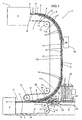
- numeral 1 shows a portion of a cigarette packing line, in its entirety.
- the line 1 in question comprises a unit 2 by which packets 3 of cigarettes are conveyed to a user machine such as a cellophaner, represented schematically in figure 1 by a block denoted 4.
- the packets 3 are turned out by an upstream unit consisting for example in a cigarette packer, shown schematically in figure 1 as a block denoted 5, and directed along the conveying unit 2 following a feed path denoted P.
- an upstream unit consisting for example in a cigarette packer, shown schematically in figure 1 as a block denoted 5, and directed along the conveying unit 2 following a feed path denoted P.
- the conveying unit 2 includes a first conveyor 6, set in continuous motion, from which packets 3 are directed into the aforementioned user machine 4, and a second conveyor 7, likewise set in continuous motion, from which packets 3 are directed onto the first conveyor 6.
- the conveyors 6 and 7 might be driven intermittently.
- the advancing packets 3 pass from the second conveyor 7 onto the first conveyor 6 at a transfer point denoted 8.
- the first conveyor 6 consists in a belt conveyor of familiar type equipped with ridges 9 combining in pairs to create respective pockets 10, each one of which accommodates a single packet 3.
- the first conveyor 6 is looped around a plurality of pulleys 11 of which at least one (not indicated) is a driving pulley, whilst the remainder are idle pulleys.
- the first conveyor 6 comprises a substantially horizontal top transport branch 12 extending along a rectilinear direction D and providing one segment of the feed path P along which the packets 3 are directed toward the cellophaner.
- the second conveyor 7 consists in a belt conveyor presenting ridges 9 that combine in pairs to establish a succession of pockets 10 each accommodating a single packet 3.
- the second conveyor 7 is looped around a plurality of pulleys 13 and rollers 14.
- pulleys denoted 13 are illustrated in the accompanying drawings, and at least one (not indicated) is power driven whilst the remainder are idle pulleys.
- the second conveyor 7, which occupies a position above the first conveyor 6, comprises a respective transport branch 15 composed of a horizontal upper infeed segment 16 on which the packets 3 emerging from the packer 5 are taken up, also a descending segment denoted 17, and a horizontal lower outfeed segment 18 facing the top transport branch 12 of the first conveyor 6 in the neighbourhood of the transfer point 8.
- the aforementioned descending segment 17 includes a substantially vertical rectilinear portion 17a, and two curvilinear connecting portions 17b and 17c merged respectively with the horizontal upper and lower segments 16 and 18.
- the unit 2 further comprises a third belt conveyor and a fourth belt conveyor, denoted 19 and 20 respectively.
- the third conveyor 19 is looped around a driving pulley 21 and around a plurality of idle rollers 22 and 23, the rollers denoted 22 occupying fixed positions, the rollers denoted 23 mounted flexibly to respective spring elements 24.
- the third conveyor 19 presents an active top branch 25 running in the direction of the arrow F in figure 2 , and a bottom return branch 26.
- the fourth conveyor 20 is looped around a driving pulley 27 and around a plurality of idle rollers 28 and 29, the rollers denoted 28 occupying fixed positions and the rollers denoted 29 mounted flexibly to respective spring elements 30.
- the fourth conveyor 20 presents an active bottom branch 31 running in the direction of the arrow F in figure 2 , and a top return branch 32.
- the two active branches 25 and 31 presented respectively by the third and fourth conveyors 19 and 20 are mutually opposed.
- the unit 2 further comprises a magazine 33 of multiple hopper type design, in which to store packets 3 releasable to the first conveyor 6 in a manner to be described in due course.
- a fifth belt conveyor 34 substantially of familiar type, not described here in detail, is positioned to coincide with an area 35 at which the packets 3 are released from the magazine 33 and serves to feed the selfsame packets 3 toward the third and fourth conveyors 19 and 20.
- the unit 2 comprises a pair of timing rollers 36 located between the third conveyor 19 and the first conveyor 6, positioned one on each side of the selfsame first conveyor 6; one only of the two rollers 36 is visible in the accompanying drawings.
- the two rollers 36 are rotatable about mutually parallel axes A1, and set in motion by drive means (not indicated) in opposing directions of rotation.
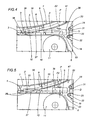
- the unit 2 comprises a guide device 37 of which the purpose is to support and allow packets 3 coming from the second conveyor 7 to slide onto the first conveyor 6, while at the same time allowing packets 3 already on the first conveyor 6 to pass directly through the transfer point 8.
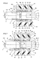
- the guide device 37 includes a plurality of pairs of bridging members 38 angled downwardly along the feed path P followed by the packets 3 along the first conveyor 6.
- the two bridging members 38 of each pair are positioned respectively on opposite sides of the feed path P and present respective portions 38a converging on the selfsame path P.
- the bridging members 38 are flexibly resilient when engaged, in a direction transverse to the rectilinear direction D aforementioned, by the advancing packets 3 carried in the pockets 10 of the first conveyor 6.
- Each bridging member 38 is incorporated into a lever element 39 embodied as a rocker and mounted to a relative fulcrum pivot 40, capable of rocking thus on a respective axis A2 independently of all the other lever elements 39.
- Each lever element 39 comprises a first arm 39a and a second arm 39b positioned on opposite sides of the pivot 40.
- the first arm 39a presents a side face 41 placed to engage the packets 3 occupying the pockets 10 of the first conveyor 6, and a flat face 42 on which the packets 3 directed along the feed path P by the second conveyor 7 are supported and able to slide.
- the aforementioned converging portion 38a is delimited by the side face 41, and thus forms a part of the first arm 39a presented by the lever element 39.
- each lever element 39 Anchored to the second arm 39b of each lever element 39 is a first end 43a of a coil spring 43, of which a second end 43b is anchored to a mounting element 44.
- the lever elements 39 are mounted sequentially in sets of three, each to a respective plate 45 carried in turn by a vertical bulkhead 46 of the frame (not illustrated) on which the conveying unit 2 is carried.
- the second conveyor 7 will be seen to comprise an element 47, extending along the descending segment 17, by means of which to guide and restrain the packets 3 advancing along the conveyor 7.
- the guiding and restraining element 47 is offered to the descending segment 17 in such a manner as to keep each of the packets 3 lodged internally of the relative pocket 10, and terminates at the transfer point 8 in a tongue 48 adjacent to the bridging members 38 of the guidance device 37.
- a proximity transducer 49 Positioned along the transport branch 15 of the second conveyor 7, at a given point upstream of the transfer point 8, is a proximity transducer 49 such as will verify the presence or absence of packets 3 in the respective pockets 10 of the conveyor 7.
- the transducer 49 provides the conveying unit 2 with relative sensing means 50 serving to detect the presence of the packets 3.
- the guide device 37 functions both as means 51 by which packets 3 advancing in the pockets 10 of the second conveyor 7 are slidably supported, and as means 52 by which packets 3 already advancing in the pockets 10 of the first conveyor 6 are afforded a passage through the transfer point 8.
- the timing rollers 36 combine with the third conveyor 19 and the fourth conveyor 20 to provide the conveying unit 2 with placement means 53 by which packets 3 are directed into the pockets 10 of the first conveyor 6.
- the conveying unit 2 will include a computerized master control unit (not illustrated) serving to manage the various operations performed by the unit 2.
- single packets 3 emerging from the packer 5 are directed onto the horizontal upper segment 16 presented by the transport branch 15 of the second conveyor 6, each one being placed, by substantially familiar methods, in a respective pocket 10 delimited by the aforementioned ridges 9.
- the packets 3 advance along the feed path P and down the descending segment 17 of the transport branch 15, supported by the guiding and restraining element 47, arriving ultimately at the point 8 of transfer to the first conveyor 6.
- the single packets 3 slide over the flat faces 42 of the lever elements 39 and locate in a respective pocket 10 presented by the top transport branch 12 of the first conveyor 6.
- a pocket 10 of the second conveyor 7 may happen to contain no packet 3, in which case the empty space is detected by the aforementioned transducer 49 located along the feed path P, upstream of the transfer point 8, and a relative signal is sent to the computerized master control unit (not illustrated).
- the computerized master control unit will pilot the placement means 53 to respond by preparing a recycled packet, denoted 3', in readiness to fill the pocket 10 of the first conveyor 6 that should have been occupied, had the missing packet 3 been transferred as normal from the second conveyor 7 to the first conveyor 6.
- the forwardmost of the packets 3' advanced by the third and fourth conveyors 19 and 20 is positioned in contact with the cylindrical surfaces of the timing rollers 36.
- the timing rollers 36 are set in contrarotation at high speed about their respective axes A1, so that when contact is made with a recycled packet 3' fed forward by the third and fourth conveyors 19 and 20, the packet 3' is accelerated to the point of locating against one ridge 9 of a predetermined pocket 10 presented by the first conveyor 6.
- the pocket 10 in question is precisely the one that would have been occupied by the packet 3 missing from the second conveyor 7.
- the aforementioned packet 3' is directed forward by a ridge 9 (not illustrated) of the corresponding pocket 10 and advanced along the feed direction D, to the point of engaging the lever elements 39 of the guide device 37.
- the lever elements 39 are caused to pivot on their respective fulcrum axes A2, spreading substantially in a transverse direction to allow the passage of the packet 3' and then closing again immediately, returned by the action of the springs 43.
- the unit 2 is equipped with a plurality of the aforementioned lever elements 39, so that the section of the feed path P covered by the guide device 37 can be split between the selfsame levers, or rather between the relative flat faces 42; in other words, observing figure 7 , whilst the lever elements 39 farthest downstream along the feed path P remain spread to allow the passage of a recycled packet 3', the elements 39 farthest upstream will already have been returned to the closed position by the action of the springs 43, in readiness to support another packet 3 advancing on the second conveyor 7. Self-evidently, in the event that two or more adjacent packets 3 may be missing on the second conveyor 7, the unit 2 is able to fill the gap by admitting two or more recycled packets 3' in succession.
- a first continuously driven conveyor 6 equipped with pockets 10 can be supplied with packets 3, through the agency of placement means 53, from a second continuously driven conveyor 7 also equipped with pockets 10, in such a way as to compensate any gaps presented by the second of the two conveyors.
- packets 3 leaving the packer 5 could be fed by the conveying unit 2 directly to the first conveyor 6, with the aforementioned transducer 49 providing sensing means 50 located alongside the first conveyor 6 and the placement means 53 operating in conjunction with the second conveyor 7 so as to direct the recycled packets 3' onto this same second conveyor 7.
- coil type return springs 43 of the lever elements 39 might be replaced by other elements equivalent in terms of the art, such as pneumatic or electric actuators (not illustrated).
- first and second conveyors 6 and 7 described and illustrated could be driven intermittently.
Landscapes
- Engineering & Computer Science (AREA)
- Mechanical Engineering (AREA)
- Wrapping Of Specific Fragile Articles (AREA)
- Branching, Merging, And Special Transfer Between Conveyors (AREA)
- Attitude Control For Articles On Conveyors (AREA)
- Control And Other Processes For Unpacking Of Materials (AREA)
- Crystals, And After-Treatments Of Crystals (AREA)
Claims (14)
- Einheit zum Fördern von Produkten an eine Verbrauchermaschine, enthaltend:- einen ersten Förderer (6) mit Fächern (10), der eine Folge von Produkten (3) zu einer Verbrauchermaschine (4) leitet;- einen zweiten Förderer (7) mit Fächern (10), der an einem Transferpunkt (8) Produkte (3) dem ersten Förderer (6) zuführt;- Fühlermittel (50), die dazu dienen, das Vorhandensein von Produkten (3) in den Fächern (10) des zweiten Förderers (7) zu erfassen;dadurch gekennzeichnet, dass die Einheit ebenfalls enthält:- Anordnungsmittel (53), verriegelt mit den Fühlermitteln (50), durch welche die Produkte (3) in die Fächer (10) des ersten Förderers (6) oder des zweiten Förderers (7) geleitet werden können, so dass eine ununterbrochene Folge von Produkten (3) erhalten wird, welche die Fächer (10) des ersten Förderers (6) stromabwärts des Transferpunktes (8) belegen.
- Fördereinheit nach Patentanspruch 1, bei welcher der erste Förderer (6) aus einer Endlosförderschlaufe besteht, aufweisend eine im wesentlichen horizontale obere Transportstrecke (12), die sich entlang einer Zuführrichtung (D) erstreckt und einen Abschnitt einer Zuführbahn (P) beschreibt, welcher die Produkte (3) folgen, während der zweite Förderer (7) aus einer Endlosförderschlaufe besteht, die oberhalb des ersten Förderers (6) angeordnet ist und eine Transportstrecke (15) enthält, die ein abfallendes Segment (17) einschliesst, sowie ein im wesentlichen horizontales Segment (18), das wenigstens dicht an dem Transferpunkt (8) der oberen Transportstrecke (12) des ersten Förderers (6) zugewandt positioniert ist.
- Fördereinheit nach Patenanspruch 1 oder 2, enthaltend Führungsmittel (37), die an dem Transferpunkt (8) angeordnet sind, und durch welche die Produkte (3) aus den Fächern (10) des zweiten Förderers (7) in die Fächer (10) des ersten Förderers (6) geleitet werden.
- Fördereinheit nach Patentanspruch 3, bei welcher die Führungsmittel (37) sei es die Aufgabe von Mitteln (51) zum gleitbaren Halten der Produkte (3) haben, welche die Fächer (10) des zweiten Förderers (7) belegen, wie auch von Mitteln (52), die einen Übergang zu den Produkten (3) bilden, welche die Fächer (10) des ersten Förderers (6) belegen.
- Fördereinheit nach Patentanspruch 4, bei welcher die Führungsmittel (37) wenigstens zwei Brückenelemente (38) enthalten, angewinkelt nach unten entlang der von den Produkten (3) auf dem ersten Förderer (6) durchlaufenen Zuführbahn (P), angeordnet auf sich gegenüberliegenden Seiten der Zuführbahn (P) selbst und enthaltend jeweilige Abschnitte (38a), die an der Zuführbahn (P) konvergieren und in einer Richtung quer zu der Zuführrichtung (D) flexibel nachgebend sind, wenn sie mit den vorlaufenden Produkten (3), welche die Fächer (10) des ersten Förderers (6) belegen, in Kontakt kommen.
- Fördereinheit nach Patentanspruch 5, bei welcher die Führungsmittel (37) eine Anzahl von Brückenelementen (38) haben.
- Fördereinheit nach Patentanspruch 5 oder 6, bei welcher jedes Brückenelement (38) in ein Hebelelement (39) eingelassen ist, in der Lage, um eine jeweilige Scharnierachse (A2) zu schwenken, unabhängig von jedem der anderen Hebelelemente (39), und eine Seitenfläche (41) aufweist, positioniert, um die aufeinanderfolgenden Produkte (3) zu greifen, welche die Fächer (10) des ersten Förderers (6) belegen, sowie eine flache Fläche (42), an welchen die durch den zweiten Förderer (7) vorlaufenden Produkte (3) gleitend gehalten sind.
- Fördereinheit nach Patentanspruch 7, bei welcher jedes der Hebelelemente (39) als Kipphebel ausgeführt ist und einen ersten Arm (39a) mit der eingelassenen Seitenfläche und der flachen Fläche (41, 42) enthält, sowie einen zweiten Arm (39b), mit welchem Federmittel (43) auf solche Weise verbunden sind, dass sie der Kippbewegung des Hebelelementes (39) entgegenwirken.
- Fördereinheit nach Patentanspruch 7 oder 8, von welcher die Führungsmittel (37) eine Anzahl von Hebelelementen (39) enthalten, angeordnet an jeder der sich gegenüberliegenden Seiten der Zuführbahn (P), welcher die Produkte (3) folgen, wobei die Hebelelemente (39) auf jeder Seite in Serie geordnet sind, und zwar auf solche Weise, dass es zwei unterschiedlichen Hebelelementen (39) auf derselben Seite erlaubt ist, gleichzeitig jeweils ein auf dem ersten Förderer (6) vorlaufendes Produkt (3) und ein auf dem zweiten Förderer (7) vorlaufendes Produkt (3) zu greifen.
- Fördereinheit nach den Patentansprüchen von 1 bis 9, bei welcher die Anordnungsmittel (53) ein Paar von Taktgeberrollen (36) enthalten, durch welche die Produkte (3) beschleunigt werden, und zwar zu dem Zweck der Positionierung eines jeden in einem jeweiligen Fach (10) des ersten Förderers (6) oder des zweiten Förderers (7).
- Fördereinheit nach Patentanspruch 10, bei welcher die Anordnungsmittel (53) einen dritten Förderer (19) enthalten, durch den die Produkte (3) zu den Taktgeberrollen (36) hin geleitet werden.
- Fördereinheit nach den Patentansprüchen von 1 bis 11, bei welcher die Fächer (10) der ersten und zweiten Förderer (6, 7) durch Erhebungen (9) abgegrenzt werden, angeordnet entlang der abwickelbaren Länge eines jeden Förderers (6, 7) und mit einem vorgegebenen Abstand eine von der nächsten.
- Fördereinheit nach den Patentansprüchen von 1 bis 12, bei welcher beide Förderer, der erste (6) und der zweite (7), kontinuierlich angetrieben sind.
- Fördereinheit nach den Patentansprüchen von 1 bis 12, bei welcher beide Förderer, der erste (6) und der zweite (7), schrittweise angetrieben sind.
Applications Claiming Priority (1)
| Application Number | Priority Date | Filing Date | Title |
|---|---|---|---|
| IT000494A ITBO20040494A1 (it) | 2004-08-03 | 2004-08-03 | Unita' di convogliamento di prodotti |
Publications (2)
| Publication Number | Publication Date |
|---|---|
| EP1623940A1 EP1623940A1 (de) | 2006-02-08 |
| EP1623940B1 true EP1623940B1 (de) | 2008-06-18 |
Family
ID=35149439
Family Applications (1)
| Application Number | Title | Priority Date | Filing Date |
|---|---|---|---|
| EP05425535A Expired - Lifetime EP1623940B1 (de) | 2004-08-03 | 2005-07-22 | Fördervorrichtung für Gegenstände |
Country Status (7)
| Country | Link |
|---|---|
| US (1) | US7644815B2 (de) |
| EP (1) | EP1623940B1 (de) |
| JP (1) | JP2006044801A (de) |
| CN (1) | CN1736828B (de) |
| AT (1) | ATE398593T1 (de) |
| DE (1) | DE602005007542D1 (de) |
| IT (1) | ITBO20040494A1 (de) |
Families Citing this family (10)
| Publication number | Priority date | Publication date | Assignee | Title |
|---|---|---|---|---|
| GB2454732A (en) * | 2007-11-17 | 2009-05-20 | Vincent Small | Packet inserter for packet wrapping system |
| US7938252B2 (en) * | 2007-12-21 | 2011-05-10 | Cinetic Sorting Corp. | Unstacking conveyor with floating surface |
| US8931240B2 (en) | 2008-10-27 | 2015-01-13 | Formax, Inc. | Shuttle system and method for moving food products into packaging |
| CN102853212B (zh) * | 2012-09-20 | 2015-08-26 | 赵炳泉 | 分仓式真空隔热板连续封装生产线及生产方法 |
| CN103204273B (zh) * | 2013-02-05 | 2016-08-03 | 天津市天驰机电技术发展有限公司 | 小包透明纸包装机烟包二次包装补入装置 |
| DE102015002798A1 (de) * | 2015-03-06 | 2016-09-08 | Focke & Co. (Gmbh & Co. Kg) | Vorrichtung zum Transport von Gegenständen, insbesondere Packungen |
| CN105540138B (zh) * | 2016-01-11 | 2017-10-27 | 昆明理工大学 | 一种烟叶运动状态测量装置 |
| BR112018016772A2 (pt) * | 2016-02-19 | 2018-12-26 | Gebo Cermex Canada Inc | detector de produto |
| IT201700099359A1 (it) * | 2017-09-05 | 2019-03-05 | Gd Spa | Sistema e metodo per la pesatura di contenitori |
| CN109941503A (zh) * | 2019-04-24 | 2019-06-28 | 漳州松田包装机械有限公司 | 一种高速枕式包装机y型双通道尾架 |
Family Cites Families (15)
| Publication number | Priority date | Publication date | Assignee | Title |
|---|---|---|---|---|
| US2603395A (en) * | 1948-07-27 | 1952-07-15 | Molins Machine Co Ltd | Collecting mechanism for cigarettes and other rod-shaped articles |
| EP0105954B1 (de) * | 1982-10-13 | 1986-05-28 | Rovema Verpackungsmaschinen Gmbh | Förderband, insbesondere für die Verwendung in Verpackungsanlagen |
| GB8924078D0 (en) * | 1989-10-26 | 1989-12-13 | Tetra Pak Ab | Continuous to intermittent feeding interface |
| US5186310A (en) * | 1992-02-05 | 1993-02-16 | Winchester Donald M | Vertical lift conveyor |
| JPH05330636A (ja) * | 1992-05-25 | 1993-12-14 | Mitsubishi Materials Corp | 長尺体の供給装置 |
| IT1260231B (it) * | 1992-12-18 | 1996-04-02 | Gd Spa | Dispositivo per alimentare articoli da fumo, in particolare sigarette,ad una macchina raggruppatrice |
| IT1260227B (it) * | 1992-12-18 | 1996-04-02 | Gd Spa | Dispositivo di alimentazione di pacchetti di sigarette ad una macchina steccatrice |
| IT1271967B (it) * | 1993-03-04 | 1997-06-10 | Geca Srl | Apparecchiatura perfezionata per il trasporto e il raggruppamento di prodotti. |
| IT1267468B1 (it) * | 1994-10-27 | 1997-02-05 | Hitech Systems Srl | Macchina perfezionata per il raggruppamento, a scopo di confezionamento, di prodotti convogliati singolarmente, |
| DE29521082U1 (de) * | 1995-06-19 | 1996-08-01 | Gerhard Schubert GmbH, 74564 Crailsheim | Gruppier- und Puffervorrichtung |
| US5971133A (en) * | 1997-05-08 | 1999-10-26 | Hk Systems, Inc. | Conveyor assembly incorporating a pop-up swivel wheel diverter |
| JP3240466B2 (ja) * | 1997-10-31 | 2001-12-17 | 株式会社フジキカイ | 包装機等の処理機械への物品供給装置 |
| DE29817239U1 (de) * | 1997-11-07 | 1998-11-26 | Hans Paal KG Maschinenbau (GmbH & Co.), 73630 Remshalden | Vorrichtung zum Zwischenspeichern |
| IT1299948B1 (it) * | 1998-04-02 | 2000-04-04 | Azionaria Costruzioni Acma Spa | Metodo e dispositivo per la formazione di gruppi di articoli appiattiti. |
| DE50204381D1 (de) * | 2001-10-15 | 2006-02-09 | Ferag Ag | Verfahren und Vorrichtung zur sequentiellen Zuführung von Gegenständen in eine Verarbeitung |
-
2004
- 2004-08-03 IT IT000494A patent/ITBO20040494A1/it unknown
-
2005
- 2005-07-22 EP EP05425535A patent/EP1623940B1/de not_active Expired - Lifetime
- 2005-07-22 DE DE602005007542T patent/DE602005007542D1/de not_active Expired - Lifetime
- 2005-07-22 AT AT05425535T patent/ATE398593T1/de not_active IP Right Cessation
- 2005-07-27 US US11/189,772 patent/US7644815B2/en not_active Expired - Fee Related
- 2005-08-01 CN CN2005100911015A patent/CN1736828B/zh not_active Expired - Fee Related
- 2005-08-02 JP JP2005224237A patent/JP2006044801A/ja active Pending
Also Published As
| Publication number | Publication date |
|---|---|
| US20060070354A1 (en) | 2006-04-06 |
| US7644815B2 (en) | 2010-01-12 |
| CN1736828B (zh) | 2010-04-21 |
| CN1736828A (zh) | 2006-02-22 |
| ATE398593T1 (de) | 2008-07-15 |
| ITBO20040494A1 (it) | 2004-11-03 |
| JP2006044801A (ja) | 2006-02-16 |
| DE602005007542D1 (de) | 2008-07-31 |
| EP1623940A1 (de) | 2006-02-08 |
Similar Documents
| Publication | Publication Date | Title |
|---|---|---|
| US4932190A (en) | Method of and apparatus for assembling and wrapping arrays of cigarette packets and the like | |
| US7497316B2 (en) | Sortation conveyor apparatus and methods | |
| US4756400A (en) | Product supply system for accumulation packaging machine | |
| CN102177080B (zh) | 用于将单列产品分成至少两列的装置 | |
| EP0480436A2 (de) | Einrichtung zum Verteilen und Sammeln von zu fördernden Produkten | |
| EP0225037B1 (de) | Verpackungsmaschine | |
| US7644815B2 (en) | Unit for conveying packs of tobacco products | |
| US6508350B1 (en) | Apparatus for avoiding falling over of objects conveyed on a conveyor system | |
| JP2004502608A (ja) | 包装機械から巻タバコ小包体を排出するための装置 | |
| US5762175A (en) | Apparatus for the ordered transportation of packs | |
| EP0624143A1 (de) | Verfahren und vorrichtung zur manipulation eines produktstromes. | |
| AU688747B2 (en) | Method and apparatus for feeding, grouping and orientating articles | |
| JPH08104423A (ja) | 不規則な製品の流れを予定の調節可能な前進速度で一つの軌道にまとめる装置及び方法 | |
| US3310151A (en) | Article combiner | |
| CN107002311B (zh) | 纺纱机 | |
| EP0130810A1 (de) | Förderband-Sortiersystem | |
| US5309697A (en) | Chewing gum packaging machine | |
| US2907155A (en) | Article transfer mechanism | |
| US3799324A (en) | Automatic cigarette feed machine | |
| US6830145B2 (en) | System for use in an assembly line | |
| SI9400125A (en) | Process and device for conveying articles, particulary for automatic packaging plants | |
| US6543600B2 (en) | Early detection photo controls | |
| US3976085A (en) | Automatic cigarette feed machine | |
| JP6734415B1 (ja) | 整列装置 | |
| GB2163717A (en) | Conveyor arrangement for rod-like articles |
Legal Events
| Date | Code | Title | Description |
|---|---|---|---|
| PUAI | Public reference made under article 153(3) epc to a published international application that has entered the european phase |
Free format text: ORIGINAL CODE: 0009012 |
|
| AK | Designated contracting states |
Kind code of ref document: A1 Designated state(s): AT BE BG CH CY CZ DE DK EE ES FI FR GB GR HU IE IS IT LI LT LU LV MC NL PL PT RO SE SI SK TR |
|
| AX | Request for extension of the european patent |
Extension state: AL BA HR MK YU |
|
| 17P | Request for examination filed |
Effective date: 20060302 |
|
| AKX | Designation fees paid |
Designated state(s): AT BE BG CH CY CZ DE DK EE ES FI FR GB GR HU IE IS IT LI LT LU LV MC NL PL PT RO SE SI SK TR |
|
| GRAP | Despatch of communication of intention to grant a patent |
Free format text: ORIGINAL CODE: EPIDOSNIGR1 |
|
| GRAS | Grant fee paid |
Free format text: ORIGINAL CODE: EPIDOSNIGR3 |
|
| GRAA | (expected) grant |
Free format text: ORIGINAL CODE: 0009210 |
|
| AK | Designated contracting states |
Kind code of ref document: B1 Designated state(s): AT BE BG CH CY CZ DE DK EE ES FI FR GB GR HU IE IS IT LI LT LU LV MC NL PL PT RO SE SI SK TR |
|
| REG | Reference to a national code |
Ref country code: GB Ref legal event code: FG4D |
|
| REF | Corresponds to: |
Ref document number: 602005007542 Country of ref document: DE Date of ref document: 20080731 Kind code of ref document: P |
|
| REG | Reference to a national code |
Ref country code: CH Ref legal event code: NV Representative=s name: BUGNION S.A. Ref country code: CH Ref legal event code: EP |
|
| REG | Reference to a national code |
Ref country code: IE Ref legal event code: FG4D |
|
| PG25 | Lapsed in a contracting state [announced via postgrant information from national office to epo] |
Ref country code: SI Free format text: LAPSE BECAUSE OF FAILURE TO SUBMIT A TRANSLATION OF THE DESCRIPTION OR TO PAY THE FEE WITHIN THE PRESCRIBED TIME-LIMIT Effective date: 20080618 Ref country code: FI Free format text: LAPSE BECAUSE OF FAILURE TO SUBMIT A TRANSLATION OF THE DESCRIPTION OR TO PAY THE FEE WITHIN THE PRESCRIBED TIME-LIMIT Effective date: 20080618 |
|
| PG25 | Lapsed in a contracting state [announced via postgrant information from national office to epo] |
Ref country code: NL Free format text: LAPSE BECAUSE OF FAILURE TO SUBMIT A TRANSLATION OF THE DESCRIPTION OR TO PAY THE FEE WITHIN THE PRESCRIBED TIME-LIMIT Effective date: 20080618 Ref country code: AT Free format text: LAPSE BECAUSE OF FAILURE TO SUBMIT A TRANSLATION OF THE DESCRIPTION OR TO PAY THE FEE WITHIN THE PRESCRIBED TIME-LIMIT Effective date: 20080618 Ref country code: PL Free format text: LAPSE BECAUSE OF FAILURE TO SUBMIT A TRANSLATION OF THE DESCRIPTION OR TO PAY THE FEE WITHIN THE PRESCRIBED TIME-LIMIT Effective date: 20080618 Ref country code: LV Free format text: LAPSE BECAUSE OF FAILURE TO SUBMIT A TRANSLATION OF THE DESCRIPTION OR TO PAY THE FEE WITHIN THE PRESCRIBED TIME-LIMIT Effective date: 20080618 |
|
| NLV1 | Nl: lapsed or annulled due to failure to fulfill the requirements of art. 29p and 29m of the patents act | ||
| PG25 | Lapsed in a contracting state [announced via postgrant information from national office to epo] |
Ref country code: CZ Free format text: LAPSE BECAUSE OF FAILURE TO SUBMIT A TRANSLATION OF THE DESCRIPTION OR TO PAY THE FEE WITHIN THE PRESCRIBED TIME-LIMIT Effective date: 20080618 Ref country code: SE Free format text: LAPSE BECAUSE OF FAILURE TO SUBMIT A TRANSLATION OF THE DESCRIPTION OR TO PAY THE FEE WITHIN THE PRESCRIBED TIME-LIMIT Effective date: 20080918 Ref country code: LT Free format text: LAPSE BECAUSE OF FAILURE TO SUBMIT A TRANSLATION OF THE DESCRIPTION OR TO PAY THE FEE WITHIN THE PRESCRIBED TIME-LIMIT Effective date: 20080618 Ref country code: IS Free format text: LAPSE BECAUSE OF FAILURE TO SUBMIT A TRANSLATION OF THE DESCRIPTION OR TO PAY THE FEE WITHIN THE PRESCRIBED TIME-LIMIT Effective date: 20081018 |
|
| PG25 | Lapsed in a contracting state [announced via postgrant information from national office to epo] |
Ref country code: SK Free format text: LAPSE BECAUSE OF FAILURE TO SUBMIT A TRANSLATION OF THE DESCRIPTION OR TO PAY THE FEE WITHIN THE PRESCRIBED TIME-LIMIT Effective date: 20080618 Ref country code: RO Free format text: LAPSE BECAUSE OF FAILURE TO SUBMIT A TRANSLATION OF THE DESCRIPTION OR TO PAY THE FEE WITHIN THE PRESCRIBED TIME-LIMIT Effective date: 20080618 Ref country code: BE Free format text: LAPSE BECAUSE OF FAILURE TO SUBMIT A TRANSLATION OF THE DESCRIPTION OR TO PAY THE FEE WITHIN THE PRESCRIBED TIME-LIMIT Effective date: 20080618 Ref country code: ES Free format text: LAPSE BECAUSE OF FAILURE TO SUBMIT A TRANSLATION OF THE DESCRIPTION OR TO PAY THE FEE WITHIN THE PRESCRIBED TIME-LIMIT Effective date: 20080929 Ref country code: PT Free format text: LAPSE BECAUSE OF FAILURE TO SUBMIT A TRANSLATION OF THE DESCRIPTION OR TO PAY THE FEE WITHIN THE PRESCRIBED TIME-LIMIT Effective date: 20081118 |
|
| PG25 | Lapsed in a contracting state [announced via postgrant information from national office to epo] |
Ref country code: MC Free format text: LAPSE BECAUSE OF NON-PAYMENT OF DUE FEES Effective date: 20080731 |
|
| PLBE | No opposition filed within time limit |
Free format text: ORIGINAL CODE: 0009261 |
|
| STAA | Information on the status of an ep patent application or granted ep patent |
Free format text: STATUS: NO OPPOSITION FILED WITHIN TIME LIMIT |
|
| REG | Reference to a national code |
Ref country code: IE Ref legal event code: MM4A |
|
| PG25 | Lapsed in a contracting state [announced via postgrant information from national office to epo] |
Ref country code: EE Free format text: LAPSE BECAUSE OF FAILURE TO SUBMIT A TRANSLATION OF THE DESCRIPTION OR TO PAY THE FEE WITHIN THE PRESCRIBED TIME-LIMIT Effective date: 20080618 Ref country code: BG Free format text: LAPSE BECAUSE OF FAILURE TO SUBMIT A TRANSLATION OF THE DESCRIPTION OR TO PAY THE FEE WITHIN THE PRESCRIBED TIME-LIMIT Effective date: 20080918 Ref country code: DK Free format text: LAPSE BECAUSE OF FAILURE TO SUBMIT A TRANSLATION OF THE DESCRIPTION OR TO PAY THE FEE WITHIN THE PRESCRIBED TIME-LIMIT Effective date: 20080618 |
|
| 26N | No opposition filed |
Effective date: 20090319 |
|
| REG | Reference to a national code |
Ref country code: FR Ref legal event code: ST Effective date: 20090529 |
|
| PG25 | Lapsed in a contracting state [announced via postgrant information from national office to epo] |
Ref country code: IE Free format text: LAPSE BECAUSE OF NON-PAYMENT OF DUE FEES Effective date: 20080722 |
|
| PG25 | Lapsed in a contracting state [announced via postgrant information from national office to epo] |
Ref country code: IT Free format text: LAPSE BECAUSE OF FAILURE TO SUBMIT A TRANSLATION OF THE DESCRIPTION OR TO PAY THE FEE WITHIN THE PRESCRIBED TIME-LIMIT Effective date: 20080618 |
|
| PG25 | Lapsed in a contracting state [announced via postgrant information from national office to epo] |
Ref country code: FR Free format text: LAPSE BECAUSE OF NON-PAYMENT OF DUE FEES Effective date: 20080731 |
|
| PG25 | Lapsed in a contracting state [announced via postgrant information from national office to epo] |
Ref country code: LU Free format text: LAPSE BECAUSE OF NON-PAYMENT OF DUE FEES Effective date: 20080722 Ref country code: HU Free format text: LAPSE BECAUSE OF FAILURE TO SUBMIT A TRANSLATION OF THE DESCRIPTION OR TO PAY THE FEE WITHIN THE PRESCRIBED TIME-LIMIT Effective date: 20081219 Ref country code: CY Free format text: LAPSE BECAUSE OF FAILURE TO SUBMIT A TRANSLATION OF THE DESCRIPTION OR TO PAY THE FEE WITHIN THE PRESCRIBED TIME-LIMIT Effective date: 20080618 |
|
| PG25 | Lapsed in a contracting state [announced via postgrant information from national office to epo] |
Ref country code: TR Free format text: LAPSE BECAUSE OF FAILURE TO SUBMIT A TRANSLATION OF THE DESCRIPTION OR TO PAY THE FEE WITHIN THE PRESCRIBED TIME-LIMIT Effective date: 20080618 |
|
| PG25 | Lapsed in a contracting state [announced via postgrant information from national office to epo] |
Ref country code: GR Free format text: LAPSE BECAUSE OF FAILURE TO SUBMIT A TRANSLATION OF THE DESCRIPTION OR TO PAY THE FEE WITHIN THE PRESCRIBED TIME-LIMIT Effective date: 20080919 |
|
| PGFP | Annual fee paid to national office [announced via postgrant information from national office to epo] |
Ref country code: CH Payment date: 20100726 Year of fee payment: 6 |
|
| PGFP | Annual fee paid to national office [announced via postgrant information from national office to epo] |
Ref country code: GB Payment date: 20110725 Year of fee payment: 7 Ref country code: DE Payment date: 20110727 Year of fee payment: 7 |
|
| REG | Reference to a national code |
Ref country code: CH Ref legal event code: PL |
|
| PG25 | Lapsed in a contracting state [announced via postgrant information from national office to epo] |
Ref country code: LI Free format text: LAPSE BECAUSE OF NON-PAYMENT OF DUE FEES Effective date: 20110731 Ref country code: CH Free format text: LAPSE BECAUSE OF NON-PAYMENT OF DUE FEES Effective date: 20110731 |
|
| GBPC | Gb: european patent ceased through non-payment of renewal fee |
Effective date: 20120722 |
|
| PG25 | Lapsed in a contracting state [announced via postgrant information from national office to epo] |
Ref country code: GB Free format text: LAPSE BECAUSE OF NON-PAYMENT OF DUE FEES Effective date: 20120722 Ref country code: DE Free format text: LAPSE BECAUSE OF NON-PAYMENT OF DUE FEES Effective date: 20130201 |
|
| REG | Reference to a national code |
Ref country code: DE Ref legal event code: R119 Ref document number: 602005007542 Country of ref document: DE Effective date: 20130201 |