EP1624146A2 - Ein Scharnier für Tür- oder Fensterrahmen - Google Patents
Ein Scharnier für Tür- oder Fensterrahmen Download PDFInfo
- Publication number
- EP1624146A2 EP1624146A2 EP05106994A EP05106994A EP1624146A2 EP 1624146 A2 EP1624146 A2 EP 1624146A2 EP 05106994 A EP05106994 A EP 05106994A EP 05106994 A EP05106994 A EP 05106994A EP 1624146 A2 EP1624146 A2 EP 1624146A2
- Authority
- EP
- European Patent Office
- Prior art keywords
- hinge
- flap
- tubular portion
- frame
- cap
- Prior art date
- Legal status (The legal status is an assumption and is not a legal conclusion. Google has not performed a legal analysis and makes no representation as to the accuracy of the status listed.)
- Granted
Links
Images


Classifications
-
- E—FIXED CONSTRUCTIONS
- E05—LOCKS; KEYS; WINDOW OR DOOR FITTINGS; SAFES
- E05D—HINGES OR SUSPENSION DEVICES FOR DOORS, WINDOWS OR WINGS
- E05D11/00—Additional features or accessories of hinges
- E05D11/0054—Covers, e.g. for protection
-
- E—FIXED CONSTRUCTIONS
- E05—LOCKS; KEYS; WINDOW OR DOOR FITTINGS; SAFES
- E05D—HINGES OR SUSPENSION DEVICES FOR DOORS, WINDOWS OR WINGS
- E05D5/00—Construction of single parts, e.g. the parts for attachment
- E05D5/02—Parts for attachment, e.g. flaps
- E05D5/04—Flat flaps
-
- E—FIXED CONSTRUCTIONS
- E05—LOCKS; KEYS; WINDOW OR DOOR FITTINGS; SAFES
- E05Y—INDEXING SCHEME ASSOCIATED WITH SUBCLASSES E05D AND E05F, RELATING TO CONSTRUCTION ELEMENTS, ELECTRIC CONTROL, POWER SUPPLY, POWER SIGNAL OR TRANSMISSION, USER INTERFACES, MOUNTING OR COUPLING, DETAILS, ACCESSORIES, AUXILIARY OPERATIONS NOT OTHERWISE PROVIDED FOR, APPLICATION THEREOF
- E05Y2900/00—Application of doors, windows, wings or fittings thereof
- E05Y2900/10—Application of doors, windows, wings or fittings thereof for buildings or parts thereof
- E05Y2900/13—Type of wing
- E05Y2900/132—Doors
-
- E—FIXED CONSTRUCTIONS
- E05—LOCKS; KEYS; WINDOW OR DOOR FITTINGS; SAFES
- E05Y—INDEXING SCHEME ASSOCIATED WITH SUBCLASSES E05D AND E05F, RELATING TO CONSTRUCTION ELEMENTS, ELECTRIC CONTROL, POWER SUPPLY, POWER SIGNAL OR TRANSMISSION, USER INTERFACES, MOUNTING OR COUPLING, DETAILS, ACCESSORIES, AUXILIARY OPERATIONS NOT OTHERWISE PROVIDED FOR, APPLICATION THEREOF
- E05Y2900/00—Application of doors, windows, wings or fittings thereof
- E05Y2900/10—Application of doors, windows, wings or fittings thereof for buildings or parts thereof
- E05Y2900/13—Type of wing
- E05Y2900/148—Windows
Definitions
- This invention relates to a hinge for door or window frames, in particular, but without restricting the scope of the invention, for metal door or window frames.
- a hinge made according to the present invention is particularly suitable for heavy or security door or window units, such as, for example, outside doors, gates and the like.
- Prior art hinges for such door or window units normally comprise two hinge bodies, usually made of extruded aluminium, and a steel hinge pin inserted into respective through holes in the hinge bodies with centring bushings inserted between the bodies and the pin.
- Each of the through holes in the hinge bodies is made coaxially in a substantially cylindrical portion of the respective hinge body itself.
- One of the hinge bodies is designed to be attached to the mobile frame of the door or window unit, and the other to the fixed frame, and each of them has a flap by which it is secured to the respective door or window frame.
- the flap which extends laterally from the substantially cylindrical portion of the hinge body, normally has two through holes, crossed, perpendicularly to the hinge pin, by securing screws whose heads are normally accommodated in respective truncated-cone shaped or countersunk seats made in the hinge flaps themselves.
- each flap has an L-shaped groove running parallel with the hinge pin and with which the cap is slidably coupled before being fixed to the hinge body by another screw that is accessible only when the door or window is open: the screw is housed in a suitable seat made in a part of the cylindrical portion of the hinge body which, during use, is in contact with the door or window unit or frame and, when the door or window is open, can be screwed into a threaded hole made in the tamper-proof cap which is thus secured to the hinge flap.
- the caps cover the whole of the large uncovered face of the hinge flaps and each forms a surface that smoothly connects with the substantially cylindrical portion of the respective hinge body, leaving this portion in view.
- a first disadvantage is due to the fact that each cap, however strong and however closely fitted to the substantially cylindrical portion of the respective hinge body may be tampered with by inserting a crowbar or similar tool between it and the cylindrical portion of the hinge in order to force the door or window open. Even if the attempt to break in is not successful, it inevitably damages the components of the hinge.
- One aim of the present invention is to provide a hinge for door or window frames with improved tamper-proof features.
- Another aim of the invention is to provide a hinge for door and window frames that is simple and economical to produce.
- this invention proposes a hinge for door or window frames comprising two hinge bodies, each consisting of a tubular portion with a first hole through the centre of it and a flap for securing it to a mobile frame or fixed frame, and a hinge pin inserted coaxially in the first holes; each flap extends laterally from the respective tubular portion and has at least one second through hole in which an element for securing the flap to the mobile frame or fixed frame can pass; each body of the hinge is also equipped with a respective cap designed to hide the securing elements from view and having a first portion for covering the respective tubular portion and a second portion for covering the respective flap, both these portions being joined as one in a single piece.
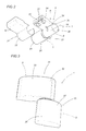
- the numeral 1 denotes in its entirety a hinge for door or window frames, in particular, but without restricting the scope of the invention, door or window frames made of metal.
- the hinge 1 is designed in particular for so-called heavy or security door or window frames, such as, for example, those of outside doors, gates and the like, and comprises two hinge bodies 2 and 3 both preferably made of extruded aluminium and each having a substantially cylindrical tubular portion 4, 5 with a respective central through hole 6, 7, and a flap 8, 9 by which it is secured to a door or window frame 10, 11.
- the door or window frame 10 to which the hinge body 2 is secured is a fixed frame, whilst the door or window frame 11 to which the hinge body 3 is secured is mobile.
- the fixed frame 10 may be absent and the hinge body 2 may be fixed directly to a load-bearing wall structure which in this case serves the same purpose as the fixed frame.
- the flap 8 extends laterally from the tubular portion 4 and has two through holes 12, aligned along a direction D1 parallel with the axis of the hole 6. There are corresponding through holes 13 in the fixed frame 10 so that it can be connected to the flap 8 using two screws 14 at a right angle to the direction of alignment D1.
- the flap 9 extends laterally from the tubular portion 5 and has two through holes 15, aligned along a direction D2 parallel with the axis of the hole 7. There are corresponding through holes 16 in the mobile frame 11 so that it can be connected to the flap 9 using two screws 17 at a right angle to the direction of alignment D2.
- the flaps 8 and 9 and the respective frames 10 and 11 have a number of through holes other than two.
- hinge 1 pin 18 The rotation of the hinge bodies 2 and 3 relative to each other is permitted by a hinge 1 pin 18.
- the hinge pin 18 is made of steel and is inserted coaxially into the holes 6 and 7 so as to enable the hinge body 2 to turn relative to the hinge body 3 about a central axis 19 of the pin 18 itself.
- the pin 18 is inserted in the holes 6 and 7 with two interposed centring bushings 20 of customary type.
- the flap 8 is laterally delimited by an end face 21, located on the side opposite the tubular portion 4 and parallel with the axis of the hole 6, and by two sides 22, both at right angles to the wall 21.
- the flap 9 may be laterally delimited by an end face 23, located on the side opposite the tubular portion 5 and parallel with the axis of the hole 7, and by two sides 24, both at right angles to the wall 23.
- the cap 25 is fitted to the body 2 by sliding the portion 26 over the portion 4 in the direction of the axis 19, with the portion 27 positioned in a plane that is rotated with respect to the plane in which the frame 10 lies, and then turning the portion 27 until it is in contact with the frame 10.
- the cap 25 which is stopped from sliding in the direction of the axis 19 by the sides 22, is fixed to the hinge body 2 by screws 41 which, with the frame 11 in the open position, are inserted into a hole 29 which passes through the portion 4 and the flap 8 and which is accessible from the above mentioned longitudinal strip (as described in more detail below).
- the axial end of the portion 4 on the side opposite the body 3 is covered by a plug 30 that is fitted by pressing it into the axial end of the portion 4 itself or, in another embodiment, into the corresponding axial end of the portion 26.
- the plug 30 may be integral, in a single piece, with the above mentioned axial end of the portion 26 (see Figure 3).
- the body 3, once fitted to the frame 11, is covered by a tamper-proof cap 31, preferably of metal, which, as shown in Figure 2, is shaped to follow the profile of the body 3 itself, with a clearly-defined edge between the tubular portion 5 and the flap 9.
- the cap 31, made in a single piece has a first portion 32, shaped in such a way as to closely surround and fully cover the lateral surface of the tubular portion 5 except for a longitudinal strip adjacent to the flap 9, and a second portion 33 shaped in such a way as to closely surround and fully cover the portion of the flap 9 that is defined by the face 23, the sides 24 and an outside face 34 of it located on the side opposite the face by which the flap 9 is in contact with the frame 11, adjacent to the above mentioned longitudinal strip.
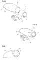
- the cap 31 is fitted to the body 3 by sliding the portion 32 over the portion 5 in the direction of the axis 19 (see arrow F) until it fully covers the portion 5 (see Figure 6) and with the portion 33 positioned in a plane that is rotated with respect to the plane in which the frame 11 lies, and then turning the portion 33 until it is in contact with the frame 11 (see arrow F1 in Figures 6 and 7).
- the cap 31 which is stopped from sliding in the direction of the axis 19 by the sides 24, is fixed to the hinge body 3 by screws 41 (according to a known method) which engage with a respective internal threaded hole 40 (see Figure 4) made in each cap 25 and 31.
- Securing occurs when the frame 11 is in the open position using a hole 35 which passes through the portion 5 and the flap 9 and which is accessible from the above mentioned longitudinal strip.
- the axial end of the portion 5 on the side opposite the body 2 is covered by a plug 36 that is fitted by pressing it into the axial end of the portion 5 itself ( Figure 2) or, in another embodiment, into the corresponding axial end of the portion 32.
- the plug 36 may be integral, in a single piece, with the above mentioned axial end of the portion 32 (see also Figure 3).
- the caps 25 and 31 are shaped in such a way as to follow the profiles of the hinge bodies 2 and 3 without clearly-defined edges between the tubular portions 4 and 5 and the respective flaps 8 and 9.
- the large outside surfaces of the portions 26 and 27 of the cap 25 are substituted by a single, outwardly convex surface, forming a smoothly curved part between the portions 26 and 27; and, in the same way, the large outside surfaces of the portions 32 and 33 of the cap 31 are substituted by a single, outwardly convex surface, forming a smoothly curved part between the portions 32 and 33.
- the inside surfaces of the portions 26 and 27 of the cap 25 are preferably shaped as in the embodiment described above, that is to say, in such a way as to closely surround the tubular portion 4 and the flap 8, respectively.
- the inside surfaces of the portions 32 and 33 of the cap 31 are preferably shaped as in the embodiment described above, that is to say, in such a way as to closely surround the tubular portion 5 and the flap 9, respectively.
- caps 25 and 31 may have different shapes and designs to meet exterior design requirements. In all embodiments, however, and if necessary, in conjunction with the plugs 30 and 36, where the latter are not integral parts of them, the caps 25 and 31 entirely cover the hinge bodies 2 and 3 when these are in the reciprocally assembled position on the respective frames 10 and 11 and the latter are in the closed position.
- a hinge made in this way achieves the preset aims thanks to covering elements or caps that are extremely practical and easy to fit and that offer a high level of security and, at the same time, have an attractive appearance.
Landscapes
- Engineering & Computer Science (AREA)
- Mechanical Engineering (AREA)
- Hinges (AREA)
Applications Claiming Priority (1)
| Application Number | Priority Date | Filing Date | Title |
|---|---|---|---|
| IT000500A ITBO20040500A1 (it) | 2004-08-03 | 2004-08-03 | Cerniera per infissi |
Publications (3)
| Publication Number | Publication Date |
|---|---|
| EP1624146A2 true EP1624146A2 (de) | 2006-02-08 |
| EP1624146A3 EP1624146A3 (de) | 2007-05-30 |
| EP1624146B1 EP1624146B1 (de) | 2009-07-01 |
Family
ID=35395770
Family Applications (1)
| Application Number | Title | Priority Date | Filing Date |
|---|---|---|---|
| EP05106994A Expired - Lifetime EP1624146B1 (de) | 2004-08-03 | 2005-07-28 | Scharnier für Tür- oder Fensterrahmen |
Country Status (4)
| Country | Link |
|---|---|
| EP (1) | EP1624146B1 (de) |
| AT (1) | ATE435355T1 (de) |
| DE (1) | DE602005015168D1 (de) |
| IT (1) | ITBO20040500A1 (de) |
Cited By (1)
| Publication number | Priority date | Publication date | Assignee | Title |
|---|---|---|---|---|
| EP2037066A2 (de) * | 2007-09-13 | 2009-03-18 | Schüring GmbH & Co. Fenstertechnologie KG | Verstellbares Flügelbandteil |
Families Citing this family (1)
| Publication number | Priority date | Publication date | Assignee | Title |
|---|---|---|---|---|
| PL65336Y1 (pl) | 2009-12-28 | 2011-03-31 | Wala Społka Z Ograniczoną Odpowiedzialnością | Zawias, zwłaszcza do drzwi |
Family Cites Families (3)
| Publication number | Priority date | Publication date | Assignee | Title |
|---|---|---|---|---|
| US2274160A (en) * | 1941-01-18 | 1942-02-24 | Bendix Home Appliances Inc | Closure construction |
| IT236021Y1 (it) * | 1997-03-18 | 2000-07-26 | Savio Spa | Cerniera per serramenti apribili ad anta, particolarmente porte efinestre |
| GB0125886D0 (en) * | 2001-10-27 | 2001-12-19 | Window Fab & Fixing Supplies | Hinge |
-
2004
- 2004-08-03 IT IT000500A patent/ITBO20040500A1/it unknown
-
2005
- 2005-07-28 AT AT05106994T patent/ATE435355T1/de not_active IP Right Cessation
- 2005-07-28 EP EP05106994A patent/EP1624146B1/de not_active Expired - Lifetime
- 2005-07-28 DE DE602005015168T patent/DE602005015168D1/de not_active Expired - Lifetime
Cited By (1)
| Publication number | Priority date | Publication date | Assignee | Title |
|---|---|---|---|---|
| EP2037066A2 (de) * | 2007-09-13 | 2009-03-18 | Schüring GmbH & Co. Fenstertechnologie KG | Verstellbares Flügelbandteil |
Also Published As
| Publication number | Publication date |
|---|---|
| EP1624146B1 (de) | 2009-07-01 |
| ATE435355T1 (de) | 2009-07-15 |
| EP1624146A3 (de) | 2007-05-30 |
| ITBO20040500A1 (it) | 2004-11-03 |
| DE602005015168D1 (de) | 2009-08-13 |
Similar Documents
| Publication | Publication Date | Title |
|---|---|---|
| US7784155B2 (en) | Simultaneous, multiple plane opening hinge | |
| US5727289A (en) | Hinge mounted adjustable door stop | |
| EP2369107B1 (de) | Band, insbesondere für Kunststofftüren und Kunststofffenster | |
| CA2941946C (en) | Fold-up window hardware | |
| US20080083089A1 (en) | Multi-axis door hinge | |
| US20130000203A1 (en) | Door assemblies | |
| US8453384B2 (en) | Child safe door, frame and hinge assembly | |
| US20010011583A1 (en) | Combination carrier and hinge for folding panels | |
| US7694388B2 (en) | Adjustable hinge | |
| EP1698752B1 (de) | Ein einstellbares Scharnier für schwere Türe und Fenster | |
| EP1624146B1 (de) | Scharnier für Tür- oder Fensterrahmen | |
| EP0667438B1 (de) | Sicherheitssystem | |
| US7059020B2 (en) | Hinge for doors and similar construction components | |
| US3937506A (en) | Door security pin | |
| US20200263465A1 (en) | Portable door lock | |
| DE10313962A1 (de) | Band, insbesondere für Dusch- und/oder Glastüren | |
| KR20000021221A (ko) | 도어용 경첩 | |
| DE202004004258U1 (de) | Scharnier und Duschabtrennung | |
| US20040261222A1 (en) | Fitting system | |
| AU2020103144A4 (en) | A Damping Apparatus for a Hinged Closure Assembly | |
| CN210460268U (zh) | 一种防刮型锁固定板 | |
| DE102004063884B4 (de) | Scharniergelenk | |
| AU749753B2 (en) | Combination carrier and hinge for folding panels | |
| GB2638938A (en) | Hinge | |
| WO2005052292A2 (en) | Hinge |
Legal Events
| Date | Code | Title | Description |
|---|---|---|---|
| PUAI | Public reference made under article 153(3) epc to a published international application that has entered the european phase |
Free format text: ORIGINAL CODE: 0009012 |
|
| AK | Designated contracting states |
Kind code of ref document: A2 Designated state(s): AT BE BG CH CY CZ DE DK EE ES FI FR GB GR HU IE IS IT LI LT LU LV MC NL PL PT RO SE SI SK TR |
|
| AX | Request for extension of the european patent |
Extension state: AL BA HR MK YU |
|
| PUAL | Search report despatched |
Free format text: ORIGINAL CODE: 0009013 |
|
| AK | Designated contracting states |
Kind code of ref document: A3 Designated state(s): AT BE BG CH CY CZ DE DK EE ES FI FR GB GR HU IE IS IT LI LT LU LV MC NL PL PT RO SE SI SK TR |
|
| AX | Request for extension of the european patent |
Extension state: AL BA HR MK YU |
|
| 17P | Request for examination filed |
Effective date: 20070703 |
|
| AKX | Designation fees paid |
Designated state(s): AT BE BG CH CY CZ DE DK EE ES FI FR GB GR HU IE IS IT LI LT LU LV MC NL PL PT RO SE SI SK TR |
|
| GRAP | Despatch of communication of intention to grant a patent |
Free format text: ORIGINAL CODE: EPIDOSNIGR1 |
|
| GRAS | Grant fee paid |
Free format text: ORIGINAL CODE: EPIDOSNIGR3 |
|
| GRAA | (expected) grant |
Free format text: ORIGINAL CODE: 0009210 |
|
| RTI1 | Title (correction) |
Free format text: HINGE FOR DOOR OR WINDOW FRAMES |
|
| AK | Designated contracting states |
Kind code of ref document: B1 Designated state(s): AT BE BG CH CY CZ DE DK EE ES FI FR GB GR HU IE IS IT LI LT LU LV MC NL PL PT RO SE SI SK TR |
|
| REG | Reference to a national code |
Ref country code: GB Ref legal event code: FG4D |
|
| REG | Reference to a national code |
Ref country code: CH Ref legal event code: EP |
|
| REG | Reference to a national code |
Ref country code: IE Ref legal event code: FG4D |
|
| REF | Corresponds to: |
Ref document number: 602005015168 Country of ref document: DE Date of ref document: 20090813 Kind code of ref document: P |
|
| PG25 | Lapsed in a contracting state [announced via postgrant information from national office to epo] |
Ref country code: SI Free format text: LAPSE BECAUSE OF FAILURE TO SUBMIT A TRANSLATION OF THE DESCRIPTION OR TO PAY THE FEE WITHIN THE PRESCRIBED TIME-LIMIT Effective date: 20090701 |
|
| NLV1 | Nl: lapsed or annulled due to failure to fulfill the requirements of art. 29p and 29m of the patents act | ||
| PG25 | Lapsed in a contracting state [announced via postgrant information from national office to epo] |
Ref country code: FI Free format text: LAPSE BECAUSE OF FAILURE TO SUBMIT A TRANSLATION OF THE DESCRIPTION OR TO PAY THE FEE WITHIN THE PRESCRIBED TIME-LIMIT Effective date: 20090701 Ref country code: EE Free format text: LAPSE BECAUSE OF FAILURE TO SUBMIT A TRANSLATION OF THE DESCRIPTION OR TO PAY THE FEE WITHIN THE PRESCRIBED TIME-LIMIT Effective date: 20090701 Ref country code: LT Free format text: LAPSE BECAUSE OF FAILURE TO SUBMIT A TRANSLATION OF THE DESCRIPTION OR TO PAY THE FEE WITHIN THE PRESCRIBED TIME-LIMIT Effective date: 20090701 Ref country code: SE Free format text: LAPSE BECAUSE OF FAILURE TO SUBMIT A TRANSLATION OF THE DESCRIPTION OR TO PAY THE FEE WITHIN THE PRESCRIBED TIME-LIMIT Effective date: 20090701 Ref country code: IS Free format text: LAPSE BECAUSE OF FAILURE TO SUBMIT A TRANSLATION OF THE DESCRIPTION OR TO PAY THE FEE WITHIN THE PRESCRIBED TIME-LIMIT Effective date: 20091101 Ref country code: AT Free format text: LAPSE BECAUSE OF FAILURE TO SUBMIT A TRANSLATION OF THE DESCRIPTION OR TO PAY THE FEE WITHIN THE PRESCRIBED TIME-LIMIT Effective date: 20090701 Ref country code: ES Free format text: LAPSE BECAUSE OF FAILURE TO SUBMIT A TRANSLATION OF THE DESCRIPTION OR TO PAY THE FEE WITHIN THE PRESCRIBED TIME-LIMIT Effective date: 20091012 |
|
| PG25 | Lapsed in a contracting state [announced via postgrant information from national office to epo] |
Ref country code: MC Free format text: LAPSE BECAUSE OF NON-PAYMENT OF DUE FEES Effective date: 20090731 Ref country code: NL Free format text: LAPSE BECAUSE OF FAILURE TO SUBMIT A TRANSLATION OF THE DESCRIPTION OR TO PAY THE FEE WITHIN THE PRESCRIBED TIME-LIMIT Effective date: 20090701 Ref country code: PL Free format text: LAPSE BECAUSE OF FAILURE TO SUBMIT A TRANSLATION OF THE DESCRIPTION OR TO PAY THE FEE WITHIN THE PRESCRIBED TIME-LIMIT Effective date: 20090701 Ref country code: LV Free format text: LAPSE BECAUSE OF FAILURE TO SUBMIT A TRANSLATION OF THE DESCRIPTION OR TO PAY THE FEE WITHIN THE PRESCRIBED TIME-LIMIT Effective date: 20090701 |
|
| REG | Reference to a national code |
Ref country code: CH Ref legal event code: PL |
|
| PLBI | Opposition filed |
Free format text: ORIGINAL CODE: 0009260 |
|
| PG25 | Lapsed in a contracting state [announced via postgrant information from national office to epo] |
Ref country code: PT Free format text: LAPSE BECAUSE OF FAILURE TO SUBMIT A TRANSLATION OF THE DESCRIPTION OR TO PAY THE FEE WITHIN THE PRESCRIBED TIME-LIMIT Effective date: 20091102 Ref country code: BG Free format text: LAPSE BECAUSE OF FAILURE TO SUBMIT A TRANSLATION OF THE DESCRIPTION OR TO PAY THE FEE WITHIN THE PRESCRIBED TIME-LIMIT Effective date: 20091001 |
|
| 26 | Opposition filed |
Opponent name: DR. HAHN GMBH & CO. KG Effective date: 20100312 |
|
| PG25 | Lapsed in a contracting state [announced via postgrant information from national office to epo] |
Ref country code: LI Free format text: LAPSE BECAUSE OF NON-PAYMENT OF DUE FEES Effective date: 20090731 Ref country code: CH Free format text: LAPSE BECAUSE OF NON-PAYMENT OF DUE FEES Effective date: 20090731 Ref country code: DK Free format text: LAPSE BECAUSE OF FAILURE TO SUBMIT A TRANSLATION OF THE DESCRIPTION OR TO PAY THE FEE WITHIN THE PRESCRIBED TIME-LIMIT Effective date: 20090701 Ref country code: RO Free format text: LAPSE BECAUSE OF FAILURE TO SUBMIT A TRANSLATION OF THE DESCRIPTION OR TO PAY THE FEE WITHIN THE PRESCRIBED TIME-LIMIT Effective date: 20090701 Ref country code: CZ Free format text: LAPSE BECAUSE OF FAILURE TO SUBMIT A TRANSLATION OF THE DESCRIPTION OR TO PAY THE FEE WITHIN THE PRESCRIBED TIME-LIMIT Effective date: 20090701 |
|
| PLAX | Notice of opposition and request to file observation + time limit sent |
Free format text: ORIGINAL CODE: EPIDOSNOBS2 |
|
| PG25 | Lapsed in a contracting state [announced via postgrant information from national office to epo] |
Ref country code: SK Free format text: LAPSE BECAUSE OF FAILURE TO SUBMIT A TRANSLATION OF THE DESCRIPTION OR TO PAY THE FEE WITHIN THE PRESCRIBED TIME-LIMIT Effective date: 20090701 Ref country code: BE Free format text: LAPSE BECAUSE OF FAILURE TO SUBMIT A TRANSLATION OF THE DESCRIPTION OR TO PAY THE FEE WITHIN THE PRESCRIBED TIME-LIMIT Effective date: 20090701 |
|
| PG25 | Lapsed in a contracting state [announced via postgrant information from national office to epo] |
Ref country code: IE Free format text: LAPSE BECAUSE OF NON-PAYMENT OF DUE FEES Effective date: 20090728 |
|
| PLAF | Information modified related to communication of a notice of opposition and request to file observations + time limit |
Free format text: ORIGINAL CODE: EPIDOSCOBS2 |
|
| PG25 | Lapsed in a contracting state [announced via postgrant information from national office to epo] |
Ref country code: GR Free format text: LAPSE BECAUSE OF FAILURE TO SUBMIT A TRANSLATION OF THE DESCRIPTION OR TO PAY THE FEE WITHIN THE PRESCRIBED TIME-LIMIT Effective date: 20091002 |
|
| PLBB | Reply of patent proprietor to notice(s) of opposition received |
Free format text: ORIGINAL CODE: EPIDOSNOBS3 |
|
| PG25 | Lapsed in a contracting state [announced via postgrant information from national office to epo] |
Ref country code: GB Free format text: LAPSE BECAUSE OF NON-PAYMENT OF DUE FEES Effective date: 20091001 |
|
| PG25 | Lapsed in a contracting state [announced via postgrant information from national office to epo] |
Ref country code: LU Free format text: LAPSE BECAUSE OF NON-PAYMENT OF DUE FEES Effective date: 20090728 |
|
| PG25 | Lapsed in a contracting state [announced via postgrant information from national office to epo] |
Ref country code: HU Free format text: LAPSE BECAUSE OF FAILURE TO SUBMIT A TRANSLATION OF THE DESCRIPTION OR TO PAY THE FEE WITHIN THE PRESCRIBED TIME-LIMIT Effective date: 20100102 |
|
| PG25 | Lapsed in a contracting state [announced via postgrant information from national office to epo] |
Ref country code: TR Free format text: LAPSE BECAUSE OF FAILURE TO SUBMIT A TRANSLATION OF THE DESCRIPTION OR TO PAY THE FEE WITHIN THE PRESCRIBED TIME-LIMIT Effective date: 20090701 |
|
| PG25 | Lapsed in a contracting state [announced via postgrant information from national office to epo] |
Ref country code: CY Free format text: LAPSE BECAUSE OF FAILURE TO SUBMIT A TRANSLATION OF THE DESCRIPTION OR TO PAY THE FEE WITHIN THE PRESCRIBED TIME-LIMIT Effective date: 20090701 |
|
| PLCK | Communication despatched that opposition was rejected |
Free format text: ORIGINAL CODE: EPIDOSNREJ1 |
|
| APBM | Appeal reference recorded |
Free format text: ORIGINAL CODE: EPIDOSNREFNO |
|
| APBP | Date of receipt of notice of appeal recorded |
Free format text: ORIGINAL CODE: EPIDOSNNOA2O |
|
| APAH | Appeal reference modified |
Free format text: ORIGINAL CODE: EPIDOSCREFNO |
|
| APBQ | Date of receipt of statement of grounds of appeal recorded |
Free format text: ORIGINAL CODE: EPIDOSNNOA3O |
|
| REG | Reference to a national code |
Ref country code: DE Ref legal event code: R100 Ref document number: 602005015168 Country of ref document: DE |
|
| APBU | Appeal procedure closed |
Free format text: ORIGINAL CODE: EPIDOSNNOA9O |
|
| PLBN | Opposition rejected |
Free format text: ORIGINAL CODE: 0009273 |
|
| STAA | Information on the status of an ep patent application or granted ep patent |
Free format text: STATUS: OPPOSITION REJECTED |
|
| 27O | Opposition rejected |
Effective date: 20150317 |
|
| REG | Reference to a national code |
Ref country code: FR Ref legal event code: PLFP Year of fee payment: 12 |
|
| REG | Reference to a national code |
Ref country code: FR Ref legal event code: PLFP Year of fee payment: 13 |
|
| REG | Reference to a national code |
Ref country code: FR Ref legal event code: PLFP Year of fee payment: 14 |
|
| P01 | Opt-out of the competence of the unified patent court (upc) registered |
Effective date: 20230506 |
|
| PGFP | Annual fee paid to national office [announced via postgrant information from national office to epo] |
Ref country code: DE Payment date: 20240730 Year of fee payment: 20 |
|
| PGFP | Annual fee paid to national office [announced via postgrant information from national office to epo] |
Ref country code: FR Payment date: 20240725 Year of fee payment: 20 |
|
| PGFP | Annual fee paid to national office [announced via postgrant information from national office to epo] |
Ref country code: IT Payment date: 20240729 Year of fee payment: 20 |
|
| REG | Reference to a national code |
Ref country code: DE Ref legal event code: R071 Ref document number: 602005015168 Country of ref document: DE |