EP1624293A2 - Signalverarbeitungssystem für eine zu testende Energieübertragungsanordnung - Google Patents
Signalverarbeitungssystem für eine zu testende Energieübertragungsanordnung Download PDFInfo
- Publication number
- EP1624293A2 EP1624293A2 EP05077423A EP05077423A EP1624293A2 EP 1624293 A2 EP1624293 A2 EP 1624293A2 EP 05077423 A EP05077423 A EP 05077423A EP 05077423 A EP05077423 A EP 05077423A EP 1624293 A2 EP1624293 A2 EP 1624293A2
- Authority
- EP
- European Patent Office
- Prior art keywords
- energy transfer
- transfer system
- arrangement
- energy
- torque
- Prior art date
- Legal status (The legal status is an assumption and is not a legal conclusion. Google has not performed a legal analysis and makes no representation as to the accuracy of the status listed.)
- Withdrawn
Links
Images






Classifications
-
- G—PHYSICS
- G01—MEASURING; TESTING
- G01M—TESTING STATIC OR DYNAMIC BALANCE OF MACHINES OR STRUCTURES; TESTING OF STRUCTURES OR APPARATUS, NOT OTHERWISE PROVIDED FOR
- G01M13/00—Testing of machine parts
- G01M13/02—Gearings; Transmission mechanisms
- G01M13/021—Gearings
-
- G—PHYSICS
- G01—MEASURING; TESTING
- G01M—TESTING STATIC OR DYNAMIC BALANCE OF MACHINES OR STRUCTURES; TESTING OF STRUCTURES OR APPARATUS, NOT OTHERWISE PROVIDED FOR
- G01M13/00—Testing of machine parts
- G01M13/02—Gearings; Transmission mechanisms
- G01M13/025—Test-benches with rotational drive means and loading means; Load or drive simulation
-
- G—PHYSICS
- G01—MEASURING; TESTING
- G01M—TESTING STATIC OR DYNAMIC BALANCE OF MACHINES OR STRUCTURES; TESTING OF STRUCTURES OR APPARATUS, NOT OTHERWISE PROVIDED FOR
- G01M13/00—Testing of machine parts
- G01M13/02—Gearings; Transmission mechanisms
- G01M13/028—Acoustic or vibration analysis
Definitions
- This invention relates generally to systems for testing electrical and mechanical energy transfer systems that exhibit vibratory and other responses to electrical or mechanical input energy, and more particularly, to an arrangement that isolates a mechanical or electrical system under test and produces signals and data corresponding to a plurality of operating characteristics of the system under test in response to the input energy.
- axles typically less than a dozen axles can be tested by a major manufacturer in one shift due to all of the above complications. This low number is not statistically valid when it is considered that most manufacturers make thousands of axles each day.
- human testers in cars are the only widely accepted method of axle testing in the industry due to the lack of a better more reliable testing method.
- This lack of a scientific basis for rating axles and gear systems is made worse when the reader considers that modem cars are extremely quiet, and are evolving to become more quite. This market direction increases the pressure on axle and other gear manufacturers to make their products quieter.
- gear and axle manufacturers There is a need for a system that offers gear and axle manufacturers a repeatable, reliable, accurate and practical way of measuring gear noise in production or laboratory environments.
- an object of this invention to provide a system for testing an energy transfer system, such as a vehicle axle, quickly and inexpensively, and achieving repeatable results.
- this invention provides, in a first method aspect thereof, a method of signal analysis for processing information from a gear system under test.
- This further method aspect includes the steps of:
- an anomaly is a bump or a nick on a tooth of the gear system under test.
- step of applying a load to the gear system under test there is provided the step of applying a load to the gear system under test.
- the further step of controlling the loading applied to the gear system under test can be responsive to the second signal.
- the torque and the noise signals are subjected to harmonic analysis. It is desired in an embodiment of the invention that is used to test gear systems, to determine whether the anomaly is a bump or a nick on a tooth of the gear system under test.
- the severity of the anomaly determined in the step of comparing is determined.
- the further method aspect of the invention can be performed exclusively with the torque signal, in certain embodiments of the invention.
- the step of sensing is provided with the step of detecting acoustic energy issued by the gear assembly. Also, the step of detecting acoustic energy issued by the gear assembly is provided with the step of placing a microphone n the vicinity of the gear assembly.
- the step of sensing is provided with the step of detecting vibratory displacement energy issued by the gear assembly.
- the step of detecting vibratory displacement energy issued by the gear assembly is provided with the further step of effecting communication between an accelerometer and the gear assembly, and the step of detecting vibratory displacement energy issued by the gear assembly is provided with the further step of effecting communication between a velocity sensor and the gear assembly.
- Sensing is effected by monitoring a first sensor that receives acoustic energy that is responsive to a qualitative condition of the gear assembly in a drive mode of operation.
- the qualitative condition of the gear assembly in the drive mode of operation includes a qualitative condition of a first surface of the teeth of the gear assembly.
- the qualitative condition of the gear assembly in the drive mode of operation includes a qualitative condition of a profile of a gear of the gear assembly, and a qualitative condition of the eccentricity of a gear of the gear assembly.
- the qualitative condition of the gear assembly in the drive mode of operation includes a qualitative condition of the angular orientation of the gears of the gear assembly.
- the qualitative condition of the gear assembly in the drive mode of operation includes a qualitative condition of a plurality of moving components of the gear assembly.
- the step of sensing is provided with the further step of monitoring a second sensor that receives acoustic energy that is responsive to a qualitative condition of the gear assembly in a coast mode of operation.
- the coast mode of operation includes a qualitative condition of a second surface of the teeth of the gear assembly.
- the qualitative condition of the gear assembly in the coast mode of operation includes a qualitative condition of a profile of a gear of the gear assembly.
- the qualitative condition of the gear assembly in the coast mode of operation includes a qualitative condition of the eccentricity of a gear of the gear assembly, as well as the angular ⁇ orientation of the gears of the gear assembly.
- the coast mode of operation includes a qualitative condition of a plurality of moving components of the gear assembly.
- the drive and coast modes of operation are cyclical over a period that is shorter than a cycle period of the input of the gear assembly.
- the period can be longer than a cycle period of the input of the gear assembly. This will depend, to an extent, upon the operating ratios within the system under test. In situations where the system under test is an electrical system, harmonics and signal distortions may affect the apparent cycle period in relation to the cycle period of the input energy.
- the first and second sensors are disposed at respective locations that are distal from each other, with the gear assembly interposed therebetween. This enables distinguishing between operating modalities of the system under test, as well as facilitating analysis of operating characteristics of the system under test that have directional components.
- an arrangement for isolating an energy transfer system while it is subjected to a test process for noise, the energy transfer system being of the type having an energy input and at least one energy output.
- the arrangement is provided with a base for supporting the arrangement and the energy transfer system.
- An isolation support supports the energy transfer system whereby the energy transfer system is translatable in at least one plane of freedom with respect to the base.
- an engagement arrangement is provided for securing the energy transfer system to the isolation support.
- a first acoustic sensor arranged at a first location in the vicinity of the energy transfer system for producing an electrical signal responsive to a noise produced by the energy transfer system under test.
- a first converter produces digital data responsive to the electrical signal, and a second converter converts the digital data into corresponding frequency components.
- a processor subjects the frequency components to analysis to determine a power spectrum density of the frequency components, and subjects the power spectrum density to harmonic analysis
- an energy supply coupled to the energy transfer system for supplying energy thereto.
- the energy transfer system is, in one embodiment of the arrangement of the present invention, a mechanical energy transfer system, and in such an embodiment, the energy supply, which is a part of the arrangement of the invention, is in the form of a source of rotatory mechanical energy.
- a rotatory coupler couples the source of rotatory mechanical energy to the energy transfer system.
- the mechanical energy transfer system test has forward and reverse directions of operation, and drive and coast modes of operation for each of the forward and reverse directions of operation.
- the mechanical energy transfer system contains at least a pair of meshed elements, at least one of the pair of meshed elements being a gear having a plurality of gear teeth thereon, the gear teeth each having first and second gear tooth surfaces for communicating with the other element of the pair of meshed elements.
- a mechanical energy transfer communication between the pair of meshed elements is effected primarily via the respective first gear tooth surfaces during forward-drive and reverse-coast modes of operation, and primarily via the respective second gear tooth surfaces during forward-coast and reverse-drive modes of operation.
- the arrangement of the present invention is provided with a first acoustic sensor arranged at a first location in the vicinity of the mechanical energy transfer system for producing a first signal that is responsive substantially to a qualitative condition of the first gear tooth surfaces.
- a second acoustic sensor is arranged at a second location in the vicinity of the mechanical energy transfer system, and produces a second signal that is responsive substantially to a qualitative condition of the second gear tooth surfaces.
- the first and second locations are distal from each other on opposite sides of the pair of meshed elements.
- a torque sensor advantageously is interposed, in a highly advantageous embodiment, between the source of rotatory mechanical energy and the energy transfer system.
- the torque sensor produces a signal that is responsive to a torque applied by the source of rotatory mechanical energy to the energy transfer system.
- the torque sensor is provided with a torque-transmitting element that has a predetermined deformation characteristic.
- the torque-transmitting element becomes deformed in response to the torque that is applied by the source of rotatory mechanical energy to the energy transfer system.
- the torque sensor further is provided with a strain sensor that is coupled to the torque-transmitting element for producing a strain signal responsive to the predetermined deformation characteristic of the torque-transmitting element.
- the strain signal therefore, is proportional to the torque.
- the torque sensor is therefore arranged to produce a static torque signal that is responsive to the magnitude of the torque required to initiate rotatory motion in the mechanical energy transfer system.
- the torque sensor be arranged to produce a dynamic torque signal that is responsive to the magnitude of torque required to maintain rotatory motion in the mechanical energy transfer system.
- the energy transfer system under test is an electrical energy transfer system
- the energy supply is provided with a source of electrical energy.
- an electrical load for receiving an output electrical energy from the energy transfer system.
- a first sensor is arranged to communicate with the energy transfer system for producing an information signal that is responsive to an operating characteristic of the energy transfer system in response to the energy supplied by the energy supply.
- the first sensor is arranged to contact the energy transfer system to produce the signal.
- the first sensor is arranged to contact the isolation support for producing the information signal.
- a microphone is provided for producing a signal that is responsive to an acoustic energy issued by the energy transfer system in response to the energy supplied by the energy supply.
- a laser sensor may additionally be provided for producing a signal that is responsive to a displacement of the energy transfer system in response to the energy supplied by the energy supply.
- an accelerometer or a velocity sensor is employed.
- the resilient support element that supports the energy transfer system in a preferred embodiment of the invention, is configured to exclude a natural frequency of any combination of the base, the engagement arrangement, and the energy transfer system.
- the vibratory or acoustic energy provided by the system under test constitutes all of the energy that would be measured and analyzed, without contribution or modification thereof by the structure of the support system.
- a thermal sensor for producing a thermal signal that is responsive to a temperature of the energy transfer system.
- the thermal sensor may be in the form of an infrared sensor that communicates optically with the energy transfer system.
- the thermal sensor means has a directional characteristic and is directed to a predetermined region of the energy transfer system for determining a rate of change of temperature of the predetermined region with respect to time.
- an acoustic sensor sensitivity control arrangement that is responsive to the thermal sensor for varying the amplitude of a noise signal in response to temperature. The variation of the amplitude of the noise signal with respect to temperature is performed in accordance with a non-linear amplitude-temperature relationship.
- Fig. 1 is a front plan representation of an arrangement for isolating a system under test, constructed in accordance with the principles of the invention.
- an isolating arrangement 10 is arranged to support in relative isolation a mechanical drive system in the form of a differential 11.
- Differential 11 is of the type that is conventionally employed in a motor vehicle (not shown) and is intended to be tested for a variety of operating conditions, using isolating arrangement 10.
- the differential is of the type having a rotatory input 13 that receives rotatory mechanical energy from a drive arrangement (not shown in this figure) that will be described below.
- differential 11 has rotatory outputs 14 and 15, respectively, that produce rotatory mechanical energy in response to the rotatory input energy received at rotatory input 13.
- differential 11 is coupled to the drive shaft (not shown) of the vehicle at rotatory input 13, and rotatory outputs 14 and 15 are coupled to the vehicle's drive wheels (not shown).
- Differential 11 is shown to be supported on a pair of supports 18 and 19 that are installed on a base 20.
- Each of supports 18 and 19 has installed thereon a respectively associated one of resilient isolating elements 22 and 23.
- a respective one of engagement arrangements 24 and 25 are installed on resilient isolating elements 22 and 23.
- the engagement arrangements will be described in detail hereinbelow and serve to couple differential I 1 at its rotatory outputs 14 and 15 whereby it is secured with respect to base 20, yet limited motion of differential 11 is permitted relative to base 20.
- Fig. 1 further shows a pair of load arrangements 28 and 29 that apply a controllable load to respectively associated ones of rotatory outputs 14 and 15.
- the rotatory outputs are coupled mechanically (coupling not shown in this figure) to load arrangements 28 and 29 in a manner that facilitates limited motion of the rotatory outputs with respect to base 20.
- the permissible displacement of differential 11 in accordance with the present invention is along multiple planes of freedom, and, as will be described hereinbelow, the coupling arrangements (not shown in this figure, between rotatory outputs 14 and 15 and their respective associated load arrangements 28 and 29 permit axial and rotative degrees of freedom of motion. Such couplings will be described with respect to Figs. 9-12.
- Fig. 2 is a side plan view of the embodiment of Fig. 1. This figure is taken along line 2-2 of Fig. 1.
- Fig. 2 shows a safety cover 30 that protects the user (not shown) of the isolating arrangement in accordance with established safety standards. Elements of structure that correspond to those discussed hereinabove with respect to Fig. 1 are similarly designated.
- Fig. 2 shows engagement arrangement 24 having engagement arms 32 and 33 that are shown in an engaged position around rotatory output 14.
- engagement arms 32 and 33 have engaged and disengaged (not shown) positions in response to actuation of an engagement driver which is shown in this figure in the form of a linear actuator 35.
- a safety cover 30 is shown to be coupled to a cover hinge 31, whereby the safety cover is rotatable thereabout in response to actuation of a cover actuator 34.
- the safety cover is arranged in the position shown in the figure during performance of the testing procedure, and it is raised to a position that is not shown in order to facilitate installation and removal of the system under test, i.e., differential 11.
- Fig. 2 additionally shows a drive motor 40, which in this embodiment, is coupled to a belt pulley 42, shown in Fig. 1.
- Fig. 3 is an exploded plan representation of the embodiment of Fig. 1 showing certain drive components. Elements of structure that have previously been discussed are similarly designated. The drive arrangement, and the manner by which it is coupled to differential 11, will be discussed in detail hereinbelow with respect to Figs. 5-8.
- Fig. 4 is a top plan view of the embodiment of Fig. 1. Elements of structure that have previously been discussed are similarly designated. Moreover, differential 11 has been removed, and therefore, is not visible in this figure.
- each of load arrangements 28 and 29 has associated therewith a respective one of load coupler arrangements 44 and 45, each of which is coupled by a respective load belt 46 and 47 to a respective one of load units 48 and 49.
- Load arrangement 28 will be described in detail hereinbelow with respect to Fig. 11, and the load coupler arrangements, 44 and 45, will be described in detail with respect to Fig. 12.
- rotatory outputs 14 and 15 are coupled (coupling not shown in this figure) to respectively associated ones of load coupler arrangements 44 and 45 which, as previously noted, provide multiple degrees of freedom of movement.
- Load units 48 and 49 are in the form of electric brakes or electric motors.
- the load units can be operated in a drag, or generator mode, wherein the differential would be operated in a simulated drive mode. That is, the load is driven by the differential.
- the load units can be operated in a motor drive mode, wherein the differential is itself driven by the load, i . e ., operated in a simulated coast mode.
- the differential can be operated and thereby tested in drive and coast modes of operation in forward and reverse directions. It is to be remembered that during drive and coast modes of operation different gear tooth surfaces (not shown) within the differential are caused to communicate with one another, thereby affording enhanced testing capability.
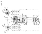
- Fig. 5 is a partially phantom front plan view of a drive arrangement that supplies rotatory mechanical energy to an isolated mechanical energy transfer system under test. Elements of structure that have previously been discussed are similarly designated. As shown in this figure, output shafts 52 and 53 are shown protruding from the fragmented representation of rotatory outputs 14 and 15, respectively. The output shafts rotate in response to the application of a rotatory drive at rotatory input 13.
- Fig. 6 is side plan view of the drive system of Fig. 5.
- the operation of the drive arrangement that will supply a rotatory drive to rotatory input 13 of differential 11 is described herein with reference to Figs. 5-9.
- drive motor 40 is coupled via a drive belt 41 to belt pulley 42 which is installed on a drive shaft 55 that is shown in the figures to extend axially vertically.
- Belt pulley 42 contains a torque sensing arrangement (not shown) that provides an electrical signal responsive to torque differential between the belt pulley and drive shaft 55.
- the electrical signal responsive to torque (not shown) is available at signal output connector 56.
- the torque sensing arrangement contained within belt pulley 42 and its associated signal output connector 56 is in the form of a strain gauge (not shown) installed to respond to the displacement of a web (not shown). That is, in the practice of this aspect of the invention, torque is transmitted across a web whereby, for example the torque is applied across the periphery of the web, and an output shaft is coupled nearer to the center of the web. Of course, these may be reversed. As torque is applied, the web is correspondingly deformed, and a strain gauge installed on the web measures the deformity in the web in response to the applied torque.
- Signal output connector 56 in this specific illustrative embodiment of the invention, additionally contains circuitry (not shown) that is AC coupled to the torque sensing arrangement, and that modulates and demodulates the resulting torque signal.
- Shaft 55 is shown in Fig. 6 to be supported against axially transverse motion by a pair of journal bearings 58.
- Drive shaft 55 therefore, rotates about its axis in response to a rotatory drive energy supplied by drive motor 40 and delivered thereto by drive belt 41.
- a coupling arrangement 60 that is fixed axially onto drive shaft 55 permits resilient axial displacement of a coupling shaft 62 with respect to the axis of drive shaft 55.
- Coupling arrangement 60 is formed of a flanged member 61 that is coupled to rotate with drive shaft 55.
- a further flanged member 63 is shown to be engaged with coupling shaft 62.
- Flanged members 61 and 63 are each provided with respective resilient elements 65 that facilitate the permissible axial displacement of coupling shaft 62 with respect to the central axis defined by drive shaft 55.
- the rotatory energy is transmitted across intermediate element 67, with which resilient elements 65 communicate.
- Fig. 7 is a side plan representation of the drive system as shown in Fig. 6, enlarged to show greater detail.
- the uppermost end of coupling shaft 62 is arranged to be connected to rotatory input 13 of differential 11 (shown in fragmented form in these figures).
- Differential 11 is of the conventional type having an hexagonal nut 69 (Fig. 7) installed at rotatory input 13.
- Rotatory input 13 is formed as a pinion shaft, and hexagonal nut 13 is threadedly engaged therewith. The application of a high tightening torque to hexagonal nut 13 during assembly of the differential prevents same from loosening during application of the rotatory energy via coupling shaft 62.
- Fig. 7 shows differential 11 in the process of being installed onto coupling shaft 62, and therefore hexagonal nut 69 is shown in two positions, where it is designated 69 and 69', respectively.
- hexagonal nut 69 becomes engaged with a nut driver 70.
- Nut driver 70 is axially translatable, and therefore is shown in two positions, where it is designated 70 and 70'.
- Fig. 8 is a side plan view of nut driver 70 that couples the drive system to the mechanical system under test.
- Fig. 9 is a top plan view of nut driver 70 of Fig. 8 showing therein three engagement surfaces for coupling with the flanks of an hexagonal nut (not shown in this figure) at the rotatory input of the mechanical system under test.
- nut driver 70 has a tapered outward appearance when viewed from the side (Fig. 8).
- nut driver 70 is provided with three engagement surfaces 71. The engagement surfaces engage with the flank surfaces of the nut (not shown) at rotatory input 13 of differential 11.
- the nut driver is, as previously noted, axially displaceable along the axis of coupling shaft 62, and is urged upward toward the nut at the rotatory input of the differential by operation of a resilient spring member 72 (Fig. 6).
- a resilient spring member 72 Fig. 6
- the nut driver is urged into communication with the nut by operation of the light resilient bias supplied by spring 72, thereby ensuring engagement between nut driver 70 and the hexagonal nut (not shown in Figs. 8 and 9) at the rotatory input of differential 11.
- the light axial bias applied by the engagement spring is negligible and affords the differential a degree of freedom of movement in the axial direction.
- sensors 73-76 are shown for monitoring various aspects of the operation of the differential in response to the application of the rotatory input.
- the various sensors are configured to monitor angular position of the rotatory input, transaxial displacement of the drive shaft, transaxial displacement of the differential in response to the application of the rotatory input energy, temperature in the region of the input bearing (not shown) of the differential, acoustic noise, etc.
- Fig. 10 is a plan representation of a clamping arrangement constructed in accordance with the principles of the invention, the clamping arrangement being shown in two positions. Elements of structure that correspond to those previously described are similarly designated.
- support 18 is coupled to base 20, illustratively via one or more fasteners 140.
- a pair of resilient support elements 141 are disposed on support element 18 and there is supported thereon an isolation support 142.
- the isolation support has a central V-shaped region 144 in the vicinity of which are installed support bearings 146 and 147.
- Rotatory output 14 of differential 11 rests on the support bearings.
- Engagement arms 32 and 33 have first and second positions corresponding to open and closed conditions. Engagement arms 32 and 33 are shown in the closed condition, wherein rotatory output 14 is clamped to support bearings 146 and 147. When the support arms are in the open position, identified as 32' and 33' (shown in phantom), the differential can be removed or installed onto isolation support 142. Actuation of the engagement arms between the open and closed conditions is effected by operation of linear actuator 35 which is coupled to the engagement arms by respectively associated ones of engagement coupler links 148 and 149. Engagement coupler links 148 and 149 are each coupled at a respective first ends thereof to a respectively associated one of engagement arms 32 and 33, and they each are coupled to one another at a central pivot coupling 150. An armature 151 of linear actuator 35 travels vertically to effect clamping and release of rotatory output 14.
- one or both of spring-loaded contacts 152 and 153 is provided with a displacements sensor 154 that produces an electrical signal, or other indication, responsive to the extent of inward translation of the spring-loaded contact.
- a displacements sensor 154 that produces an electrical signal, or other indication, responsive to the extent of inward translation of the spring-loaded contact.
- Such an indication would be responsive to the outside dimension of the rotatory output of differential 11, thereby providing a means for determining dimensional variations of the differential housing (not specifically identified in this figure) during a production run.
- Fig. 11 is a compact drive arrangement constructed in accordance with the invention for coupling the rotatory output of a mechanical energy transfer system under test (not shown in this figure) to a rotatory load, which will be described hereinbelow in the form of an electric rotatory device that is operable in drive and generator modes.
- a load arrangement 80 is provided with a load motor 81 having a belt pulley 82 arranged to rotate with a load motor shaft 83.
- pulley 82 is coupled to a further belt pulley 85 via a load belt 86.
- Pulley 85 is coupled to a tubular shaft 89 having a flanged portion 90 that is arranged in axial communication with tubular shaft 89.
- belt pulley 82 in Fig. 11 contains a torque sensing arrangement 87 that provides an electrical signal (not shown) responsive to a torque differential between the belt pulley and load motor shaft 83.
- the electrical signal responsive to torque is available at signal output connector 84, as described below.
- torque sensing arrangement 87 contained within belt pulley 82 and its associated signal output connector 84 include a strain gauge 88 installed to respond to the displacement of a web 92. That is, in the practice of this aspect of the invention, torque is transmitted across web 92 wherein, for example, the torque is applied across the periphery of the web, and an output shaft 98 is coupled nearer to the center of the web. Of course, the application of the torque may be rotationally reversed. As the torque is applied, web 92 is correspondingly deformed, and strain gauge 88 installed on the web measures the deformity in the web in response to the applied torque. Over a predetermined range of torque, the deformation of web 92, as determined by measurement of the electrical response of strain gauge 88 at signal output connector 84, can be correlated to the magnitude of the applied torque.
- signal output connector 84 in Fig. 11 additionally contains circuitry (not shown) that is AC coupled to the torque sensing arrangement, and that modulates and demodulates the resulting torque signal.
- the torque signal will be to a significant extent responsive to the load or drive characteristic of load motor 81, which is controllable by the application of appropriate electrical signals (not shown) or connection of electrical loads (not shown) at electrical terminals 99 thereof.
- Tubular shaft 89 is supported rotatably by ball bearings 91.
- a resilient element 93 that is secured to remain in communication with pulley 85 by operation of an end cap 94.
- End cap 94 has internally affixed thereto a load shaft 95 that is arranged to extend along the interior length of tubular shaft 89.
- any rotatory element (not shown in this figure) that would be coupled to load shaft 95 at its associated coupler 97 would be provided with freedom of motion in any direction transverse to the axis of rotation of the load shaft, and therefore would not be constrained in the axially transverse direction.
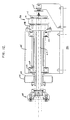
- Fig. 12 is a partially cross-sectional side plan view of a compact drive arrangement similar in some respects to that of Fig. 11.
- This figure shows a shaft support system 100 that provides the degree of freedom of motion discussed hereinabove with respect to the embodiment of Fig. 11, and additionally provides axial thrust support.
- Shaft support system 100 is provided with a pulley 101 that can be coupled to another rotatory element (not shown) via a belt 102.
- the pulley is fixed to a tubular shaft 104 that is axially fixed in a support 105 by ball bearings 106.
- the tubular shaft is expanded radially to form a shaft portion 108 having a large diameter than the central portion of the tubular shaft.
- a resilient coupling arrangement that is generally designated as 110 is resiliently coupled to shaft portion 108.
- Resilient coupling arrangement 110 is provided with an intermediate plate 111 and an end plate 112 that are resiliently coupled to one another whereby they rotate with tubular shaft 104.
- a central shaft 114 is coupled at its right-most end to end plate 112 so as to be rotatable therewith. The central shaft, however, experiences freedom of movement in all directions transverse to its axis of rotation. Any travel of central shaft 114 toward the right hand side is limited by an end stop 115, which is arranged, in this embodiment, to provide a measure of axial adjustment.
- the other end of central shaft 114 is coupled to a resilient coupling arrangement which is generally designated as 117.
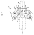
- Fig. 13 is a partially phantom enlarged representation of the resilient coupling element shown in Fig. 12.
- Resilient coupling element 117 is shown in this figure in an expanded form to facilitate this detailed description.
- Central shaft 114 (Fig. 12) has a reduced diameter end portion 120 on which is installed a flanged washer 121 having a reduced diameter portion 122 and a flange 123 formed therearound.
- a further flanged element 125 is installed on reduced diameter end portion 120 of central shaft 114, a shear pin 127 being disposed between flanged washer 121 and further flanged element 125.
- annular portion 128 is arranged to surround the flanged washer and the further flanged element, and to overlie circumferentially the axial region where resilient element 127 is disposed. All of these elements are secured to reduced diameter end portion 120 of central shaft 114 by a fastener 129 and a washer 130. As shown, fastener 129 is threadedly engaged axially onto the end of central shaft 114.
- a support portion 132 is fixed onto further flanged element 125 by fasteners 133.
- Support portion 132 is resiliently coupled to a flanged shaft 135 by means of studs 136.
- resilient coupling arrangement 117 provides yet further freedom of movement in all directions transverse to the axis of rotation for flanged shaft 135.
- Flanged shaft 135, in one embodiment of the invention, is ultimately coupled to a rotatory output, such as rotatory output 15 of Fig. 1.
- shaft support system 100 can be used in the drive arrangement of Fig. 6 to provide significant degree of motion lateral to the axis of rotation to the drive shaft.
- Fig. 14 is an isometric representation of an arrangement for isolating a system under test, the isolation system being constructed in accordance with the principles of the invention.
- the system under test is an electrical energy transfer device.
- an isolation support 160 isolates an electrical energy transfer device, illustratively in the form of an electrical transformer 162.
- the electrical transformer is secured to an isolation base 164 by operation of a toggle locking device 165.
- Isolation base 164 is mechanically isolated from a ground surface 166 by a plurality of resilient isolation elements 170. That is, the isolation base is permitted freedom of movement in at least one plane of motion, and preferably a plurality of planes of motion, by operation of the resilient isolation elements.
- the resilient isolation elements have a resilience characteristic that, as previously noted in regard of other embodiments of the invention, exclude a natural frequency of isolation support 160 and transformer 162.
- the motion of the transformer and the isolation support is therefore responsive substantially entirely to the electrical energy that is transferred to or from transformer 162 via its electrical terminals 172.
- Fig. 15 is a process diagram of a typical process for conducting an energy analysis of a gear system.
- gears under test 180 are driven by a drive 181, the speed of which is controlled by a speed control 183.
- Information relating to the drive speed is conducted to a digital data storage system 185.
- Analog sensors 187 obtain analog data from gears under test 180, the analog signals from the sensors being conducted to an A/D converter 188.
- the A/D converter performs the conversion of the analog signals in response to a clock 190, and the resulting digital data is conducted to digital data storage system 185.
- digital data storage system 185 contains the digitized analog signals obtained from sensors 187, which data is correlated to the speed at which gears under test 180 are driven.
- the digital data of digital data storage system 185 is converted to the frequency domain by subjecting same to a fast Fourier transform at step 193.
- the resulting frequency components are then ordered at step 194 and analyzed manually at step 195.
- the collected data, in the frequency domain is analyzed in the context of predetermined test criteria.
- the pass/fail decision is then made at step 197, and if the predetermined criteria is not met, a "fail" indication is produced at step 198. Otherwise, a "pass” indication is issued at step 199.
- Fig. 16 is a process diagram of a process for conducting an energy analysis in accordance with the principles of the present invention.
- gears under test 201 are driven into rotation by a drive system 202, which also drives an encoder 204.
- Encoder 204 delivers signals responsive to the rotation of gears under test 201 to an A/D converter 206.
- the signal from encoder 204 serves as a pacing clock for the A/D converter.
- Information relating to noise and displacement issued by the gears under test is collected by analog sensors 207.
- the resulting analog signals are conducted to A/D converter 206 where they are converted to digital signals correlated to the rotation of drive system 202.
- the digital signals from A/D converter 206 are conducted to a digital data store 210 where they are maintained in correlation to the drive information obtained from encoder 204.
- the digital data is stored two-dimensionally, wherein sensor signal amplitude is identified with the y-axis, and rotational position is identified with the x-axis.
- the correlated digital data is subjected to a fast Fourier transform at step 212 wherein the data is converted into its frequency components.
- Data in the frequency domain is subjected to processing at step 214, where a power spectrum density is created using a data window.
- the power spectrum density data is then analyzed harmonically at step 215 to determine its relationship with predetermined test criteria.
- the decision whether the power spectrum density data passes or fails with respect to predetermined test criteria is made at step 216, and the predetermined criteria is not met, a "fail" indication is produced at step 217. Otherwise, a "pass” indication is issued at step 218.
- Fig. 17 is a diagram of a process for conducting an analysis 230 in accordance with the principles of the present invention for determining bumps and nicks in a mechanical energy transfer system.
- gears under test 231 are driven into rotation by a drive system 232, via a torque sensor 234.
- Torque sensor 234 delivers signals responsive to the rotatory force supplied to gears under test 231 to an A/D converter 236.
- Information relating to noise and displacement issued by the gears under test is collected by noise sensors 237, which may include velocity sensors (not shown in this figure), accelerometers (not shown in this figure), microphones (not shown in this figure), etc.
- the resulting noise signals are conducted to A/D converter 236 where they are converted to digital signals correlated to the torque applied by drive system 232 to gears under test 231.
- the digital signals from A/D converter 236 are conducted to a digital data store 240 where they are maintained in correlation to the drive information obtained from torque sensor 234.
- the digital data is stored as two two-dimensional data sets, wherein noise sensor signal amplitude is identified with a first y-axis, and time is identified with the x-axis.
- the amplitude of the torque signal is identified with a second y-axis, and time is again identified with the x-axis.
- Correlated data from digital data store 240 is subjected to analysis at step 242, wherein peaks that occur simultaneously in the torque and noise signal waveforms are identified. These peaks are then measured at step 244 to determine whether they exceed predetermined thresholds. Those peaks that exceed the predetermined thresholds are then tested at step 245 against the harmonics of each gear tooth frequency, to determine whether the peaks correspond to anomalous conditions.
- step 246 The decision whether the gears under test pass or fail with respect to predetermined test criteria is made at step 246, and if the predetermined criteria is not met, a "fail” indication is produced at step 247. Otherwise, a "pass” indication is issued at step 248. In some embodiments of the invention, a calculation of the severity of the bumps or nicks that caused the anomalous conditions is calculated at step 249.
- torque sensor 234 delivers signals responsive to the rotatory force supplied to gears under test 23 1 to A/D converter 236, and the digital data is stored as a single two-dimensional data set, wherein the amplitude of the torque signal is identified with the y-axis, and time is identified with the x-axis.
- Peaks in the torque signal are then measured at step 244 to determine whether they exceed a predetermined threshold. Those peaks that exceed the predetermined thresholds are then tested at step 245 against the harmonics of each gear tooth frequency, to determine whether the peaks correspond to anomalous conditions.
- step 246 The decision whether the gears under test pass or fail with respect to predetermined test criteria is made at step 246, and if the predetermined criteria is not met, a "fail” indication is produced at step 247. Otherwise, a "pass” indication is issued at step 248. As previously noted, a calculation of the severity of the bumps or nicks that caused the anomalous condition is calculated at step 249.
Landscapes
- Physics & Mathematics (AREA)
- General Physics & Mathematics (AREA)
- Acoustics & Sound (AREA)
- Testing Of Devices, Machine Parts, Or Other Structures Thereof (AREA)
- Measurement Of Mechanical Vibrations Or Ultrasonic Waves (AREA)
- Emergency Protection Circuit Devices (AREA)
- Testing Relating To Insulation (AREA)
- Testing Electric Properties And Detecting Electric Faults (AREA)
- Measurement Of Resistance Or Impedance (AREA)
- Automatic Analysis And Handling Materials Therefor (AREA)
- Circuit Arrangement For Electric Light Sources In General (AREA)
Applications Claiming Priority (2)
| Application Number | Priority Date | Filing Date | Title |
|---|---|---|---|
| US09/107,096 US6170326B1 (en) | 1998-06-29 | 1998-06-29 | Signal processing system for energy transfer arrangement under test |
| EP99932136A EP1092138B1 (de) | 1998-06-29 | 1999-06-29 | Signalverarbeitungsverfahren zum testen einer vorrichtung zur energieübertragung |
Related Parent Applications (1)
| Application Number | Title | Priority Date | Filing Date |
|---|---|---|---|
| EP99932136A Division EP1092138B1 (de) | 1998-06-29 | 1999-06-29 | Signalverarbeitungsverfahren zum testen einer vorrichtung zur energieübertragung |
Publications (1)
| Publication Number | Publication Date |
|---|---|
| EP1624293A2 true EP1624293A2 (de) | 2006-02-08 |
Family
ID=22314813
Family Applications (2)
| Application Number | Title | Priority Date | Filing Date |
|---|---|---|---|
| EP05077423A Withdrawn EP1624293A2 (de) | 1998-06-29 | 1999-06-29 | Signalverarbeitungssystem für eine zu testende Energieübertragungsanordnung |
| EP99932136A Expired - Lifetime EP1092138B1 (de) | 1998-06-29 | 1999-06-29 | Signalverarbeitungsverfahren zum testen einer vorrichtung zur energieübertragung |
Family Applications After (1)
| Application Number | Title | Priority Date | Filing Date |
|---|---|---|---|
| EP99932136A Expired - Lifetime EP1092138B1 (de) | 1998-06-29 | 1999-06-29 | Signalverarbeitungsverfahren zum testen einer vorrichtung zur energieübertragung |
Country Status (9)
| Country | Link |
|---|---|
| US (3) | US6393902B1 (de) |
| EP (2) | EP1624293A2 (de) |
| JP (1) | JP2002519662A (de) |
| AT (1) | ATE329243T1 (de) |
| AU (1) | AU4851099A (de) |
| CA (1) | CA2336281A1 (de) |
| DE (1) | DE69931782D1 (de) |
| MX (1) | MXPA01000225A (de) |
| WO (1) | WO2000000805A2 (de) |
Families Citing this family (21)
| Publication number | Priority date | Publication date | Assignee | Title |
|---|---|---|---|---|
| US6389888B1 (en) * | 1998-06-29 | 2002-05-21 | Veri-Tek Inc. | Isolation and loading arrangement for differential gear system under test |
| US6393902B1 (en) * | 1998-06-29 | 2002-05-28 | Veri-Tek Inc. | Noise testing system with temperature responsive sensitivity |
| US6523422B1 (en) * | 1998-06-29 | 2003-02-25 | Veri-Tek Inc. | Isolation arrangement for system under test |
| US6705022B2 (en) | 2001-10-16 | 2004-03-16 | Metso Minerals Industries, Inc. | Method and apparatus for determining a pinion bearing move to align a pinion-to-gear assembly |
| US6662671B1 (en) | 2002-07-22 | 2003-12-16 | Visteon Global Technologies, Inc. | Gear driven mechanical assembly test procedure |
| US7140252B2 (en) * | 2004-05-04 | 2006-11-28 | Ford Motor Company | Structurally tuned vibration based component checking system and method |
| DE102006044829A1 (de) * | 2006-09-20 | 2008-04-03 | GIF Gesellschaft für Industrieforschung mbH | Prüfstand zum Messen von NVH-Eigenschaften eines Getriebeprüflings, Anschlusswelle für einen Prüfstand, Verwendung einer Adapterwelle und Verfahren zum Messen von NVH-Eigenschaften |
| CN100549651C (zh) * | 2006-10-26 | 2009-10-14 | 奇瑞汽车股份有限公司 | 汽车变速器的高速动力损失试验方法 |
| FR2911398B1 (fr) * | 2007-01-12 | 2009-02-27 | Renault Sas | Procede de detection de defauts dans une boite de vitesses |
| US8214104B2 (en) * | 2007-04-17 | 2012-07-03 | Kabushiki Kako Co., Ltd. | Abnormal noise inspection method for anti-vibration device for vehicle use |
| CN102549405B (zh) * | 2009-07-31 | 2015-12-16 | Mts系统公司 | 风力涡轮机传动系统测试组件 |
| JP5434899B2 (ja) * | 2010-12-24 | 2014-03-05 | 三菱自動車工業株式会社 | 車両用減速機の振動試験装置 |
| CN105675127B (zh) * | 2012-09-06 | 2019-04-16 | 浙江吉利汽车研究院有限公司杭州分公司 | 汽车排气尾管噪声测试装置以及测试方法 |
| US9632012B2 (en) * | 2015-07-01 | 2017-04-25 | GM Global Technology Operations LLC | Vehicle differential housing and method of NVH testing |
| CN105241544B (zh) * | 2015-09-28 | 2018-08-21 | 南京航空航天大学 | 基于近场声阵列的转子噪声源识别方法 |
| CN105547693B (zh) * | 2015-12-29 | 2018-01-02 | 安徽农业大学 | 一种四驱汽车分动器加载检测试验台 |
| US10488372B2 (en) * | 2017-08-16 | 2019-11-26 | General Electric Company | Systems and methods for detecting damage in rotary machines |
| CN109211546B (zh) * | 2018-08-28 | 2020-05-26 | 电子科技大学 | 基于降噪自动编码器及增量学习的旋转机械故障诊断方法 |
| CN109916620B (zh) * | 2019-04-17 | 2020-08-25 | 哈尔滨理工大学 | 一种齿轮传动噪声检测与分析系统 |
| DE102024109887A1 (de) | 2024-04-09 | 2025-10-09 | Jw Froehlich Maschinenfabrik Gmbh | Prüfvorrichtung für elektrische Antriebseinheiten |
| CN121702738B (zh) * | 2026-01-21 | 2026-07-28 | 中国航发湖南动力机械研究所 | 一种内外啮合结构的均载测试方法和装置 |
Family Cites Families (29)
| Publication number | Priority date | Publication date | Assignee | Title |
|---|---|---|---|---|
| US3400578A (en) * | 1965-12-06 | 1968-09-10 | Curtiss Wright Corp | Acoustical analyser for indicating faults in operative parts of highspeed engines |
| US3521158A (en) | 1968-01-11 | 1970-07-21 | Ird Mechanalysis | Inductive vibration pickup apparatus |
| US3635050A (en) * | 1969-11-25 | 1972-01-18 | Woodward Governor Co | Drive transmission with universal couplings |
| US3712130A (en) * | 1970-10-30 | 1973-01-23 | Gen Electric | Detection of distributed defects in gear assemblies |
| US3731661A (en) * | 1971-12-27 | 1973-05-08 | T Hatfield | Rotary engine apparatus |
| US3855847A (en) * | 1972-06-20 | 1974-12-24 | Westinghouse Electric Corp | Acoustic emission transducer and monitoring system |
| CH592302A5 (de) | 1974-08-12 | 1977-10-31 | Laue Guenter | |
| US4331003A (en) * | 1979-07-26 | 1982-05-25 | Barry Wright Corporation | Flexible coupling |
| US4252023A (en) | 1979-11-27 | 1981-02-24 | Illinois Tool Works Inc. | Vibration testing system for gear sets |
| JPS59164938A (ja) * | 1983-03-09 | 1984-09-18 | Mitsubishi Electric Corp | 歯車異常音検出装置 |
| JPS59174732A (ja) | 1983-03-24 | 1984-10-03 | Mitsubishi Electric Corp | ギアユニツトの異常判定装置 |
| US4643035A (en) * | 1985-05-10 | 1987-02-17 | Murphy Wesley T | Energy transfer and conservation apparatus |
| US4711124A (en) * | 1986-03-24 | 1987-12-08 | General Motors Corporation | Torque applier |
| US4729239A (en) | 1986-12-19 | 1988-03-08 | Mpb Corporation | Vibration tester for ball bearings and associated devices |
| US4788856A (en) * | 1987-10-13 | 1988-12-06 | Dana Corporation | Method and apparatus for checking differential gear assemblies |
| US4931949A (en) | 1988-03-21 | 1990-06-05 | Monitoring Technology Corporation | Method and apparatus for detecting gear defects |
| US4875373A (en) | 1988-07-25 | 1989-10-24 | Westinghouse Electric Corp. | Temperature compensated fiber optic vibration sensor |
| DE3926281C2 (de) | 1989-08-09 | 1995-10-12 | Daimler Benz Ag | Geräuschprüfstand für Pkw-Getriebe |
| ATE94247T1 (de) | 1990-02-15 | 1993-09-15 | Vaw Flussspat Chemie Gmbh | Vefahren zum korrosionsschutz an schnittflaechen von bewehrten gasbeton-bauteilen und vorrichtung zur durchfuehrung des verfahrens. |
| US5309378A (en) | 1991-11-18 | 1994-05-03 | Hughes Aircraft Company | Multi-channel adaptive canceler |
| US5224377A (en) | 1992-08-12 | 1993-07-06 | Gei Systems, Inc. | Rigid test table for gear sets |
| DE4328537C2 (de) | 1993-08-25 | 2000-03-30 | Univ Stuttgart | Getriebeprüfstand und Verfahren zum Prüfen eines Getriebes |
| US5513519A (en) * | 1994-09-23 | 1996-05-07 | David M. Cauger | Method of measuring changes in the energy transfer efficiency of a thermal transfer system |
| US5537865A (en) | 1995-01-03 | 1996-07-23 | Shultz; Duane E. | Apparatus and methods for testing transmissions |
| US5825657A (en) | 1996-02-23 | 1998-10-20 | Monitoring Technology Corporation | Dynamic, non-uniform clock for resampling and processing machine signals |
| KR100201492B1 (ko) | 1996-07-26 | 1999-06-15 | 류정열 | 디퍼렌셜 기어 조립체 소음 측정장치 |
| US5800331A (en) | 1997-10-01 | 1998-09-01 | Song; Jin Y. | Imbalance detection and rotor identification system |
| US6523422B1 (en) * | 1998-06-29 | 2003-02-25 | Veri-Tek Inc. | Isolation arrangement for system under test |
| US6393902B1 (en) * | 1998-06-29 | 2002-05-28 | Veri-Tek Inc. | Noise testing system with temperature responsive sensitivity |
-
1998
- 1998-06-29 US US09/107,086 patent/US6393902B1/en not_active Expired - Fee Related
- 1998-06-29 US US09/107,096 patent/US6170326B1/en not_active Expired - Fee Related
-
1999
- 1999-06-29 EP EP05077423A patent/EP1624293A2/de not_active Withdrawn
- 1999-06-29 CA CA002336281A patent/CA2336281A1/en not_active Abandoned
- 1999-06-29 JP JP2000557127A patent/JP2002519662A/ja active Pending
- 1999-06-29 MX MXPA01000225A patent/MXPA01000225A/es not_active IP Right Cessation
- 1999-06-29 DE DE69931782T patent/DE69931782D1/de not_active Expired - Fee Related
- 1999-06-29 AU AU48510/99A patent/AU4851099A/en not_active Abandoned
- 1999-06-29 WO PCT/US1999/014896 patent/WO2000000805A2/en not_active Ceased
- 1999-06-29 AT AT99932136T patent/ATE329243T1/de not_active IP Right Cessation
- 1999-06-29 EP EP99932136A patent/EP1092138B1/de not_active Expired - Lifetime
-
2002
- 2002-05-28 US US10/157,707 patent/US6736002B2/en not_active Expired - Fee Related
Also Published As
| Publication number | Publication date |
|---|---|
| EP1092138B1 (de) | 2006-06-07 |
| MXPA01000225A (es) | 2002-10-17 |
| US6393902B1 (en) | 2002-05-28 |
| ATE329243T1 (de) | 2006-06-15 |
| DE69931782D1 (de) | 2006-07-20 |
| WO2000000805A9 (en) | 2000-11-02 |
| US6736002B2 (en) | 2004-05-18 |
| JP2002519662A (ja) | 2002-07-02 |
| WO2000000805A3 (en) | 2000-04-13 |
| US20030010102A1 (en) | 2003-01-16 |
| US6170326B1 (en) | 2001-01-09 |
| WO2000000805A2 (en) | 2000-01-06 |
| AU4851099A (en) | 2000-01-17 |
| EP1092138A2 (de) | 2001-04-18 |
| CA2336281A1 (en) | 2000-01-06 |
Similar Documents
| Publication | Publication Date | Title |
|---|---|---|
| US6170326B1 (en) | Signal processing system for energy transfer arrangement under test | |
| US6877368B2 (en) | Isolation and loading arrangement for differential gear system under test | |
| US7204161B2 (en) | Isolation arrangement for system under test | |
| US6182515B1 (en) | Coupler arrangement for isolation arrangement for system under test | |
| US6523422B1 (en) | Isolation arrangement for system under test | |
| EP1092137B1 (de) | Geräuschprüfsystem mit temperaturabhängiger empfindlichkeit | |
| WO1995005607A3 (en) | Transducer testing system for low frequency vibrations | |
| CN211121975U (zh) | 轮边电机轴承动态冲击载荷的测量装置 | |
| CN117433725A (zh) | 整体叶轮的叶片振动位移应变关系标定试验方法 | |
| RU2224232C1 (ru) | Способ виброакустической диагностики передач зацеплением | |
| CN122016345A (zh) | 一种汽车传动轴总成扭转疲劳测试设备 |
Legal Events
| Date | Code | Title | Description |
|---|---|---|---|
| PUAI | Public reference made under article 153(3) epc to a published international application that has entered the european phase |
Free format text: ORIGINAL CODE: 0009012 |
|
| AC | Divisional application: reference to earlier application |
Ref document number: 1092138 Country of ref document: EP Kind code of ref document: P |
|
| AK | Designated contracting states |
Kind code of ref document: A2 Designated state(s): AT BE CH CY DE DK ES FI FR GB GR IE IT LI LU MC NL PT SE |
|
| STAA | Information on the status of an ep patent application or granted ep patent |
Free format text: STATUS: THE APPLICATION IS DEEMED TO BE WITHDRAWN |
|
| 18D | Application deemed to be withdrawn |
Effective date: 20070101 |