EP1624366A1 - Stockage d'une structure dans un dispositif électronique - Google Patents
Stockage d'une structure dans un dispositif électronique Download PDFInfo
- Publication number
- EP1624366A1 EP1624366A1 EP05254393A EP05254393A EP1624366A1 EP 1624366 A1 EP1624366 A1 EP 1624366A1 EP 05254393 A EP05254393 A EP 05254393A EP 05254393 A EP05254393 A EP 05254393A EP 1624366 A1 EP1624366 A1 EP 1624366A1
- Authority
- EP
- European Patent Office
- Prior art keywords
- mouse
- bay
- connection
- electronic device
- power
- Prior art date
- Legal status (The legal status is an assumption and is not a legal conclusion. Google has not performed a legal analysis and makes no representation as to the accuracy of the status listed.)
- Withdrawn
Links
Images





Classifications
-
- G—PHYSICS
- G06—COMPUTING OR CALCULATING; COUNTING
- G06F—ELECTRIC DIGITAL DATA PROCESSING
- G06F3/00—Input arrangements for transferring data to be processed into a form capable of being handled by the computer; Output arrangements for transferring data from processing unit to output unit, e.g. interface arrangements
- G06F3/01—Input arrangements or combined input and output arrangements for interaction between user and computer
- G06F3/03—Arrangements for converting the position or the displacement of a member into a coded form
- G06F3/033—Pointing devices displaced or positioned by the user, e.g. mice, trackballs, pens or joysticks; Accessories therefor
- G06F3/0354—Pointing devices displaced or positioned by the user, e.g. mice, trackballs, pens or joysticks; Accessories therefor with detection of two-dimensional [2D] relative movements between the device, or an operating part thereof, and a plane or surface, e.g. 2D mice, trackballs, pens or pucks
- G06F3/03543—Mice or pucks
-
- G—PHYSICS
- G06—COMPUTING OR CALCULATING; COUNTING
- G06F—ELECTRIC DIGITAL DATA PROCESSING
- G06F1/00—Details not covered by groups G06F3/00 - G06F13/00 and G06F21/00
- G06F1/16—Constructional details or arrangements
- G06F1/1613—Constructional details or arrangements for portable computers
- G06F1/1615—Constructional details or arrangements for portable computers with several enclosures having relative motions, each enclosure supporting at least one I/O or computing function
- G06F1/1616—Constructional details or arrangements for portable computers with several enclosures having relative motions, each enclosure supporting at least one I/O or computing function with folding flat displays, e.g. laptop computers or notebooks having a clamshell configuration, with body parts pivoting to an open position around an axis parallel to the plane they define in closed position
-
- G—PHYSICS
- G06—COMPUTING OR CALCULATING; COUNTING
- G06F—ELECTRIC DIGITAL DATA PROCESSING
- G06F1/00—Details not covered by groups G06F3/00 - G06F13/00 and G06F21/00
- G06F1/16—Constructional details or arrangements
- G06F1/1613—Constructional details or arrangements for portable computers
- G06F1/1626—Constructional details or arrangements for portable computers with a single-body enclosure integrating a flat display, e.g. Personal Digital Assistants [PDAs]
-
- G—PHYSICS
- G06—COMPUTING OR CALCULATING; COUNTING
- G06F—ELECTRIC DIGITAL DATA PROCESSING
- G06F1/00—Details not covered by groups G06F3/00 - G06F13/00 and G06F21/00
- G06F1/16—Constructional details or arrangements
- G06F1/1613—Constructional details or arrangements for portable computers
- G06F1/1632—External expansion units, e.g. docking stations
-
- G—PHYSICS
- G06—COMPUTING OR CALCULATING; COUNTING
- G06F—ELECTRIC DIGITAL DATA PROCESSING
- G06F1/00—Details not covered by groups G06F3/00 - G06F13/00 and G06F21/00
- G06F1/16—Constructional details or arrangements
- G06F1/1613—Constructional details or arrangements for portable computers
- G06F1/1633—Constructional details or arrangements of portable computers not specific to the type of enclosures covered by groups G06F1/1615 - G06F1/1626
- G06F1/1656—Details related to functional adaptations of the enclosure, e.g. to provide protection against EMI, shock, water, or to host detachable peripherals like a mouse or removable expansions units like PCMCIA cards, or to provide access to internal components for maintenance or to removable storage supports like CDs or DVDs, or to mechanically mount accessories
-
- G—PHYSICS
- G06—COMPUTING OR CALCULATING; COUNTING
- G06F—ELECTRIC DIGITAL DATA PROCESSING
- G06F1/00—Details not covered by groups G06F3/00 - G06F13/00 and G06F21/00
- G06F1/26—Power supply means, e.g. regulation thereof
- G06F1/266—Arrangements to supply power to external peripherals either directly from the computer or under computer control, e.g. supply of power through the communication port, computer controlled power-strips
-
- A—HUMAN NECESSITIES
- A63—SPORTS; GAMES; AMUSEMENTS
- A63F—CARD, BOARD, OR ROULETTE GAMES; INDOOR GAMES USING SMALL MOVING PLAYING BODIES; VIDEO GAMES; GAMES NOT OTHERWISE PROVIDED FOR
- A63F2300/00—Features of games using an electronically generated display having two or more dimensions, e.g. on a television screen, showing representations related to the game
- A63F2300/10—Features of games using an electronically generated display having two or more dimensions, e.g. on a television screen, showing representations related to the game characterized by input arrangements for converting player-generated signals into game device control signals
- A63F2300/1043—Features of games using an electronically generated display having two or more dimensions, e.g. on a television screen, showing representations related to the game characterized by input arrangements for converting player-generated signals into game device control signals being characterized by constructional details
Definitions
- users may prefer to utilize these electronic devices with specific controls or accessories. For example, a user may prefer a gaming experience using a game controller or interface similar to that employed when using a dedicated gaming console. Similarly, a user watching video or listening to music stored on a portable electronic device may desire to use a familiar remote control or interface.
- portable and handheld computers as well as other types of portable electronic devices, are designed to be easily and conveniently transported, it is inconvenient to carry separate equipment, such as controllers, cables, connectors, and so forth, with the device.
- portable electronic devices may use insertable memory media, such as memory cards or sticks, it may be undesirable to carry additional, loose media with the device.
- Fig. 1 depicts an embodiment of a portable computer and an insertable structure, in accordance with aspects of the present invention.
- Fig. 2 depicts an embodiment of a handheld computer and an insertable structure, in accordance with aspects of the present invention.
- Fig. 3 depicts an embodiment of a remote control device configured to be inserted into a peripheral card slot of an electronic device, in accordance with aspects of the present invention.
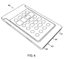
- Fig. 4 depicts an embodiment of a remote control device configured to be inserted into a peripheral card slot of an electronic device and to be charged within the slot, in accordance with aspects of the present invention.
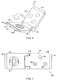
- Fig. 5 depicts an embodiment of a foldable game controller configured to be inserted into a peripheral card slot of an electronic device, in accordance with aspects of the present invention.
- Fig. 6 depicts the foldable game controller of Fig. 5 being unfolded, in accordance with aspects of the present invention.
- Fig. 7 depicts the foldable game controller of Fig. 5 when unfolded, in accordance with aspects of the present invention.
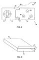
- Fig. 8 depicts an alternate embodiment of a game controller including a storable cable, in accordance with aspects of the present invention.
- Fig. 9 depicts an embodiment of a storage structure configured to be inserted into a peripheral card slot of an electronic device, in accordance with aspects of the present invention.
- Fig. 10 depicts an embodiment of a cable storage structure configured to be inserted into a peripheral card slot of an electronic device, in accordance with aspects of the present invention.
- Fig. 11 depicts an embodiment of a battery charging structure configured to be inserted into a peripheral card slot of an electronic device, in accordance with aspects of the present invention.
- Fig. 12 depicts in a somewhat schematic and partly exploded view an embodiment of a mouse configured to be inserted into a peripheral card slot of an electronic device, in accordance with aspects of the present invention.
- certain embodiments of the present invention comprise a method, apparatus, or system for storing auxiliary equipment for use with an electronic device, such as a portable or handheld computer, a personal digital assistant (PDA), a digital camera or camcorder, an audio player (such as a player configured to play files in accordance with a Motion Picture Experts Group, Audio Layer 3 (MP3) standard), or other portable or non-portable electronic devices.
- PDA personal digital assistant
- MP3 Motion Picture Experts Group, Audio Layer 3
- Some exemplary embodiments utilize user-accessible peripherals or memory device bays in the housing of the electronic device that are configured to interface with insertable components or media, such as peripheral cards, storage devices, or memory cards.
- a device bay may comprise one or more peripheral card slots, such as slots configured to receive peripheral cards adhering to a Personal Computer Memory Card International Association (PCMCIA) standard or an express card standard.
- a device bay may comprise slots adapted to engage and read various media, such as optical disks, magnetic disks, memory cards, or other memory media.
- a device bay may comprise a bay or compartment configured to accommodate a storage device or reader, such as optical and floppy disk drives or removable hard drives.
- a storage device or reader such as optical and floppy disk drives or removable hard drives.
- Fig. 1 depicts an embodiment of an electronic device in the form of a portable computer 10, such as a laptop, notebook, or tablet computer.
- the housing 12 of the portable computer 10 includes a variety of device bays configured to receive removable components or media that operate within the bay.
- a device bay may be configured to directly connect to a suitably configured device, such as by an electrical interface, when the device is inserted into the bay.
- the inserted device may operate with other components with which it is electrically connected, such as with a bus, memory, or processor in the interior of the portable computer 10.
- the housing 12 includes one or more peripheral card slots 14, such as PCMCIA or express card slots, that are configured to electrically interface/connect with a peripheral card, such as a network adapter, modem, or removable hard drive.
- peripheral cards of this type are generally designed to provide increased functionality to the portable computer 10 when inserted into a respective bay or slot such that they properly interface with a respective electrical connector when inserted into the bay.
- many structures such as, and without limitation, electronic apparatuses, storage containers, chargeable structures, etc., can be configured so as to lack a suitable connector to directly connect to the bay's interface, although such structures may interact with the electronic device via other communication avenues, e.g., a wireless connection, a separate cable to connect to a dedicated outlet in the device housing, etc.
- the corresponding bay such as the depicted peripheral card slot 14 may be vacant.
- the vacant bay is utilized, in accordance with embodiments of the present invention, to securely store other equipment or devices, such as the structure 16.
- the structure 16 when not in use, is configured to be able to reside in a bay, where residing is defined to encompass being retained in, fitting within, or being positionable partly, entirely, or mostly within the confines of the bay.
- the structure 16 is ejected using the ejection mechanism typically used to remove the peripheral card or other removable device for which the slot or bay is configured.
- the user simply pulls on the structure 16 with sufficient force to overcome the resistive or engaging force holding the structure 16 within the bay, such as the peripheral card slot 14.
- the structure 16 is an electronic apparatus, such as a universal serial bus (USB) hub or an input device or a control device, that communicates with or connects to the portable computer 10. Communication or connection to the portable computer 10, however, does not have to occur via the connectors present within the slot or bay in which the structure 16 is stored.
- the structure 16 may be a controller or other input device which, when not stored within the bay, may communicate, without limitation, with the portable computer 10 via wireless means, such as over the infrared or radio frequencies, or via a cable connection to a dedicated interface in the housing of portable computer 10. Examples of some electronic apparatuses would be a remote control, a game controller, and optical and non-optical mice.
- the structure 16 connects to the connector(s) within a respective bay, such as peripheral card slot 14.
- structure 16 can be connected within a bay to charge a battery of structure 16.
- a connection between the structure 16 and the connector(s) enables power, but not data, to pass between the structure 16 and portable computer 10 or other electronic device.
- a chargeable component of the structure 16, such as a battery may charge from a power supply of the portable computer 10 or from power delivered to the portable computer 10, such as via an AC power cord plugged into an electrical outlet.
- the structure 16 is charged when not in use, (i.e., when stored in a device bay), so that the charged structure 16 is ready for use (i.e., its intended functionalities) when removed from the bay or at other times.
- the controller or input device of the preceding example may include a chargeable battery that is charged when stored in the bay via a limited or dedicated connection to an electrical interface within the depicted peripheral card slots 14. In such a limited interface, minimal or no communicative connection exists between the structure 16 and the portable computer 10 or other electronic device. '
- the structure 16 may be an electronic device, as set forth in the preceding examples, it may also be a simple mechanical structure, such as a storage container. In such an embodiment, the structure 16 may be used to store any item capable of fitting into the structure 16. For instance, equipment for use with the portable computer 10 or with other electronic devices may be stored in this manner.
- a storage structure may be used to store a variety of memory media that may be read by the portable computer 10 or by another electronic device. Examples of such storable memory media include memory sticks, memory cards, including secure digital (SD) memory cards, multimedia cards (MMC), mini-optical disks, and so forth.
- cables, such as network, telephone, or USB cables usable with the portable computer 10 or with other electronic devices may be stored in a suitable structure 16.
- items unrelated to the use of the portable computer 10 such as paper clips, rubber bands, gum, and so forth, may also be stored in this manner so that a user may store and carry other items, even if not related to the use of the electronic device.
- Embodiments in accordance with the present invention include a wide variety of portable and/or non-portable electronic devices.
- a portable electronic device such as a PDA or handheld computer 20
- the portable electronic device includes a user-accessible device bay, such as a memory card slot or a peripheral card slot 14, which may be used for storage and/or other functions when slot 14 is vacant.
- other electronic devices such as MP3 and other audio players, digital cameras and camcorders, portable digital video disk (DVD) players, and so forth, may include compartments or bays for the insertion of functional components or memory media which, when empty, may be used to store other equipment or media for use with the device or another electronic device.
- a remote control 30 is depicted that is configured to be inserted and securely held within a PCMCIA card slot, such as may be found on a portable or handheld computer.
- the remote control 30 includes spacers 32 which prevent the remote control 30 from contacting the electrical connectors located in a PCMCIA card slot of an electronic device. In this way, the connectors within the PCMCIA card slot are not damaged by insertion and storage of the remote control 30 into the slot.
- the spacers 32 enable an ejection mechanism found within a PCMCIA card slot to eject the remote control 30 when the ejection mechanism is actuated.
- the remote control 30 of Fig. 3 is powered from a battery and does not contact the connectors located within a device bay, e.g., a PCMCIA card slot.
- the remote control 30 may include receptacles or contacts on the spacers 32 which contact respective power connectors at the end of the bay to enable recharging of a power supply in the remote control.
- the spacers 32 enable the remote control 30 to be charged when stored in a bay but prevent the remote control 30 from contacting or damaging other interface structures within the bay.
- the chargeable remote control 40 is configured to be charged when stored within a device bay, e.g., a PCMCIA card slot.
- the chargeable remote control 40 includes all or part of a charging interface 42 for coupling with connectors within a peripheral card slot.
- the charging interface 42 does not include a full complement of receptacles or contacts for engaging the full set of available connectors 46 (depicted in Fig. 5) of the peripheral card slot 14. Instead, the charging interface 42 is configured to connect to some or all of the power pins 48 of the complementary peripheral card slot interface.
- the chargeable remote control 40 includes power pin receptacles 44 for engaging and electrically coupling to the power pins of a peripheral card slot, that is, for example, pins 1, 17, 34, 35, 51, and 68 of a PCMCIA card slot.
- a battery or other chargeable medium within the chargeable remote control 40 may be charged when control 40 is not in use and while stored in a peripheral card slot or other bay.
- a foldable game controller 50 is depicted.
- the depicted game controller comprises a first portion 52 and a second portion 54 connected by a hinge 56.
- the game controller 50 is insertable into and removable from a pair of vacant peripheral card slots 14.
- the two portions 52 and 54 of the game controller 50 may be unfolded to an open position, as depicted in Fig.
- the game control interface 59 includes action and pause buttons 60 and a directional control 62, such as a joystick interface.
- the depicted game controller 50 communicates with a suitable gaming device, such as a portable or handheld computer, via wireless means.
- the game controller 50 includes a compartment, such as hinge compartment 58, within which a battery is inserted to power the game controller 50.
- one or more charging interfaces 42 are provided to charge the battery of game controller 50 when stored in the peripheral card slots 14.
- the power pin receptacles 44 of the charging interface 42 engage some or all of the respective power pins 48 of the available connectors 46.
- the charging interfaces 42 may be absent and the battery is replaced by the user as needed instead of being charged when stored in a respective bay.
- a cable-connected game controller 64 is provided, as depicted in Fig. 8.
- a cable 66 and connector 68 such as a USB connector, may be stored in the hinge compartment 58.
- the cable-connected game controller 64 is powered through the cable 66 when the connector 68 is inserted into a complementary receptacle of a gaming device, such as a portable or handheld computer.
- the cable-connected game controller 64 may be battery-powered and/or chargeable, as described above.
- cable 66 and connector 68 do not have to be stored in hinge compartment 58 but may instead be stored as desired within the game controller 64.
- controllers and other input devices represent one type of apparatus which may be inserted for storage within a bay of an electronic device
- a storage structure 70 configured to be stored in a slot or bay of an electronic device is depicted in Fig. 9.
- the storage structure 70 encloses a storage space 72, which can be accessed by moving all or part of a movable section 74 of the storage structure housing.
- a hinged movable section 74 of the storage structure housing is such that the movable section 74 may be rotated between open and closed positions.
- the movable section 74 may be configured to slide between open and closed positions or may be configured to move in other ways known to those of ordinary skill in the art.
- the accessible storage space 72 may be used to store media, such as memory cards or memory sticks, for use with a reader of the electronic device or another electronic device. Though the storage of memory media is one possibility, in practice, any item or items of interest capable of fitting into the storage structure 70 may be stored by a user. For example, replacement parts, such as screws, nuts, bolts, etc., for equipment may be stored in the storage space 72. Similarly, office supplies, such as paper clips, rubber bands, adhesive flags, and so forth, may be stored in the storage space 72 if a user so desires.
- the storage structure 70 thus, comprises a storage device or compartment that can repeatedly be inserted into and removed from a bay of an electronic device.
- a cable storage structure 80 is provided which is configured to be stored in a slot or bay of an electronic device.
- the depicted cable storage structure 80 is configured to store at least one type of cable 82, such as network cable, telephone cable, USB cable, and so forth.
- the stored cable 82 is withdrawn from the cable storage structure 80 and used to connect respective sockets or plugs that the connectors 84 are configured to fit.
- the cable 82 is accessible when the cable storage structure 80 is stored in a slot or bay of an electronic device, though this need not be the case in all embodiments.
- a charging structure 90 is provided.
- the charging structure 90 includes a charging interface 42 that may be used to connect to some or all of the power pins of a peripheral card slot, such as a PCMCIA slot, or other power connectors in the bay into which the charging structure 90 is inserted.
- the charging structure 90 includes a battery receptacle 92 configured to receive one or more batteries 94 for charging.
- the depicted charging structure 90 also includes a battery ejection mechanism, which is activated by the ejection button 96, to facilitate the unloading of the battery 94 from the structure 90. In other embodiments, no ejection mechanism may be provided other than the force applied by a user to overcome a resistive force holding the battery 94 in the charging structure 90.
- a mouse another embodiment of a storable structure, indicated generally by the reference sign 100, is a mouse.
- the mouse 100 may be an optical mouse and is powered by a rechargeable battery 116 in the mouse.
- the mouse 100 communicates wirelessly with the portable computer 10 or other portable electronic device.
- the mouse 100 may be configured to communicate with a Bluetooth radio networking device with which the portable computer 10 or other portable electronic device is equipped.
- the mouse 100 is formatted as a device to fit in a PCMCIA Type III device bay 14 (see Figure 5).
- the mouse 100 may alternatively be of another shape and/or size, to fit in another format of device bay 14.
- a PCMCIA Type III device is nominally 85.6 mm long, 54 mm wide, and 10.5 mm thick. This is smaller than a typical computer mouse but is large enough for the embodiment of the mouse 100 shown in Figure 12 to be ergonomically acceptable in ordinary use.
- the mouse 100 is thinned to a thickness of approximately 3 mm, and terminates in a charging interface 42 similar to that shown in Figure 4.
- the interface in a PCMCIA Type III bay 14 consists of two PCMCIA Type I/II connectors one alongside the other, so that the PCMCIA Type III slot can be used for two PCMCIA Type I/II devices.
- the charging interface 42 of the mouse 100 is arranged to engage with one of the two connectors 46 in the bay 14.
- the PCMCIA standard allows for power pins in the interface that are not controlled by a device driver in the host computer. Therefore, the mouse 100 can be configured to connect to the power pins without connecting to any data pins, and without needing a PCMCIA device driver to be installed.
- the battery in the mouse 100 is then charged under control of a charger 118 in the mouse, while the PCMCIA bay passively supplies power to the charger.
- the charging interface 42 in the mouse may consist of a standard connector with only the power pins, and not the data pins, operatively connected within the mouse.
- the mouse in the embodiment has a body 105 rising to the full 10.5 mm height allowed by the PCMCIA Type III format.
- the mouse may be thinner than 10.5 mm.
- the full height of the mouse 100 is continued from the finger end 104 for most of the length and width of the mouse.
- a thinner or thicker format may be utilized.
- the finger end 104 of the mouse 100 has two mouse buttons 106, 108 and a scroll wheel 110.
- Other arrangements are possible, including a mouse with three mouse buttons or a mouse with two buttons and no scroll wheel.
- the finger end 104 of the mouse 100 is typically exposed in the mouth of the bay.
- the finger end 104 of the mouse 100 is therefore preferably generally flat and flush with the surface of the computer 12 that surrounds the PCMCIA bay 14.
- the finger end 104 of the mouse 100 can project outside of the computer 12 a short distance when the mouse is fully inserted in the PCMCIA bay 14. In that alternative embodiment the mouse 100 is longer than the standard length of the PCMCIA bay 14.
- the projecting finger end can be thicker than the height of the PCMCIA bay 14.
- the finger end 104 of the mouse 100 does not need to occupy the entire rectangular shape of the mouth of the PCMCIA bay 14.
- the sides 112 of the mouse 100 are the same thickness as the end 102 with the power connector 42, in order to fit under the guide rails that are present along the sides of a PCMCIA Type III bay 14.
- the finger end 104 of the mouse 100 can project outside of the computer 12 a short distance when the mouse is fully inserted in the PCMCIA bay 14. In that alternative embodiment the mouse 100 is longer than the standard length of the PCMCIA bay 14.
- the projecting finger end can be thicker than the height of the PCMCIA bay 14.
- the body 105 of the mouse may contain a transmitter 114 for the Bluetooth or other wireless connection, the rechargeable battery 116, the battery charger 118 for controlling the charging of the battery 116 from the continuously powered power pins of the connector 46, and the tracker and transducers 120 for movement of the mouse, clicks of the buttons 106, 108, and movement of the scroll wheel 110, that provide the actual mouse functionality.
- the mouse 100 is ejected from the PCMCIA bay 14 and is used as an ordinary cordless mouse.
- the mouse is used as seen from above in Fig. 12, with the full height at the finger end 104 and over the middle part 105 of the mouse, and with the thin end 102 and thin sides 112 downwards towards a mouse pad or other surface on which the mouse is being used.
- the user can grasp the middle part 105 of the mouse, and the heel of the user's hand can rest on the thin end 102.
- the mouse 100 can be inserted in the PCMCIA bay 14, where the mouse can recharge its battery.
- the mouse 100 In the PCMCIA bay 14, the mouse 100 is out of the way, is protected from loss or damage, and remains with the computer 10 so that it is reliably available when it is wanted. No separate charging device or cord is needed for the mouse 100.
- the finger end 104 can be flush with a side or end of the electronic device. As such the mouse 100 will not protrude or project outwardly from the housing of the electronic device.
Landscapes
- Engineering & Computer Science (AREA)
- Theoretical Computer Science (AREA)
- General Engineering & Computer Science (AREA)
- Computer Hardware Design (AREA)
- Physics & Mathematics (AREA)
- General Physics & Mathematics (AREA)
- Human Computer Interaction (AREA)
- Mathematical Physics (AREA)
- Power Sources (AREA)
- Position Input By Displaying (AREA)
Applications Claiming Priority (2)
| Application Number | Priority Date | Filing Date | Title |
|---|---|---|---|
| US10/903,106 US20060023410A1 (en) | 2004-07-30 | 2004-07-30 | Apparatus for storing a structure within an electronic device |
| US10/989,047 US7280351B2 (en) | 2004-07-30 | 2004-11-15 | Storing a structure within an electronic device |
Publications (1)
| Publication Number | Publication Date |
|---|---|
| EP1624366A1 true EP1624366A1 (fr) | 2006-02-08 |
Family
ID=35447578
Family Applications (1)
| Application Number | Title | Priority Date | Filing Date |
|---|---|---|---|
| EP05254393A Withdrawn EP1624366A1 (fr) | 2004-07-30 | 2005-07-13 | Stockage d'une structure dans un dispositif électronique |
Country Status (4)
| Country | Link |
|---|---|
| US (2) | US7280351B2 (fr) |
| EP (1) | EP1624366A1 (fr) |
| JP (1) | JP4088640B2 (fr) |
| TW (1) | TWI372987B (fr) |
Cited By (2)
| Publication number | Priority date | Publication date | Assignee | Title |
|---|---|---|---|---|
| WO2009117052A1 (fr) * | 2008-03-21 | 2009-09-24 | Goldbaum Harold J | Dispositif de pointage à bas profil pour ordinateurs personnels |
| CN104881082A (zh) * | 2014-02-27 | 2015-09-02 | 起源技术美国股份有限公司 | 具有移动usb端口的平板电脑壳 |
Families Citing this family (14)
| Publication number | Priority date | Publication date | Assignee | Title |
|---|---|---|---|---|
| KR100663644B1 (ko) * | 2004-12-10 | 2007-01-03 | 삼성전자주식회사 | 마우스 및 이를 갖는 휴대용 컴퓨터 |
| US7330923B2 (en) * | 2005-03-21 | 2008-02-12 | Avago Technologies Ecbu Ip (Singapore) Pte. Ltd. | Input devices and methods of operating same |
| US7719517B2 (en) * | 2005-06-21 | 2010-05-18 | Microsoft Corporation | Input device for a computer system |
| US20080094785A1 (en) * | 2006-10-20 | 2008-04-24 | First Data Corporation | Communication device housing systems and methods |
| US20090113104A1 (en) * | 2007-10-31 | 2009-04-30 | Wenstand John S | Input devices and methods of operating same |
| JP2009139659A (ja) * | 2007-12-06 | 2009-06-25 | Fujitsu Component Ltd | 電子機器、遠隔操作装置充電方法 |
| USD624539S1 (en) * | 2009-06-12 | 2010-09-28 | A-Data Technology (Suzhou) Co., Ltd. | Portable electronic storage device |
| CN102117101B (zh) * | 2009-12-31 | 2013-12-11 | 鸿富锦精密工业(深圳)有限公司 | 笔记本电脑 |
| US20120162885A1 (en) * | 2010-12-22 | 2012-06-28 | Panasonic Corporation | Information processing apparatus |
| US9098254B2 (en) * | 2011-03-30 | 2015-08-04 | Dell Products L.P. | Multi-purpose information handling system device connector |
| US20130249358A1 (en) * | 2012-03-23 | 2013-09-26 | Huckleberry Toys | Portable Mobile Device Protective Cover |
| US8861192B2 (en) * | 2012-11-09 | 2014-10-14 | Yi-Ming Huang | Electronic device designed for holding high-definition multimedia interface connector |
| DE102013014925B3 (de) * | 2013-09-11 | 2015-03-12 | Burkard Thomann | Aufnahmevorrichtung zur Aufnahme von einem Computer in Tafel- oder Tablettform |
| USD1051226S1 (en) * | 2022-03-16 | 2024-11-12 | Samsung Display Co., Ltd. | Electronic games console |
Citations (5)
| Publication number | Priority date | Publication date | Assignee | Title |
|---|---|---|---|---|
| US6035350A (en) * | 1997-01-21 | 2000-03-07 | Dell Usa, L.P. | Detachable I/O device with built-in RF/IR functionality to facilitate remote audio-visual presentation |
| US6091404A (en) * | 1993-12-07 | 2000-07-18 | Hong; Seung Seog | Trackball for a portable computer |
| EP1400890A1 (fr) * | 2001-09-03 | 2004-03-24 | Tai-Her Yang | Système radio T/R universel |
| US20040140955A1 (en) * | 2003-01-21 | 2004-07-22 | Metz Kristofer Erik | Input device for a computer and method of operation |
| EP1443387A1 (fr) * | 2003-01-13 | 2004-08-04 | Uniwill Computer Corporation | Dispositif d'entrée détachable |
Family Cites Families (8)
| Publication number | Priority date | Publication date | Assignee | Title |
|---|---|---|---|---|
| US5080452A (en) * | 1990-03-01 | 1992-01-14 | Tuckman Tab R | Integral storage receptacle for personal computer |
| US5861873A (en) * | 1992-06-29 | 1999-01-19 | Elonex I.P. Holdings, Ltd. | Modular portable computer with removable pointer device |
| KR100229602B1 (ko) * | 1997-04-12 | 1999-11-15 | 윤종용 | 포인팅장치를 장착가능한 유무선 겸용의 입력장치 및 이를 사용하는 컴퓨터 시스템 |
| KR100259264B1 (ko) * | 1997-10-02 | 2000-06-15 | 윤종용 | 두 타입의 포인팅 입력부를 갖는 유무선 겸용 포인팅 장치 및 이를 사용하는 컴퓨터 시스템 |
| JP2001125662A (ja) * | 1999-08-18 | 2001-05-11 | Fujitsu Ltd | 情報処理装置用の認証情報入力手段付き拡張装置、認証情報入力ユニット及び情報処理装置 |
| US6476795B1 (en) * | 2000-01-20 | 2002-11-05 | Hewlett-Packard Company | Mouse recharging module |
| US6665741B1 (en) * | 2000-10-17 | 2003-12-16 | Hewlett-Packard Development Company, L.P. | Portable computer with removable I/O device |
| US20050270735A1 (en) * | 2004-06-07 | 2005-12-08 | Che-Chih Chen | Remote control holding unit |
-
2004
- 2004-11-15 US US10/989,047 patent/US7280351B2/en not_active Expired - Lifetime
-
2005
- 2005-06-30 TW TW094122078A patent/TWI372987B/zh not_active IP Right Cessation
- 2005-07-13 EP EP05254393A patent/EP1624366A1/fr not_active Withdrawn
- 2005-07-20 JP JP2005209597A patent/JP4088640B2/ja not_active Expired - Fee Related
-
2007
- 2007-07-30 US US11/830,521 patent/US7675745B2/en not_active Expired - Fee Related
Patent Citations (5)
| Publication number | Priority date | Publication date | Assignee | Title |
|---|---|---|---|---|
| US6091404A (en) * | 1993-12-07 | 2000-07-18 | Hong; Seung Seog | Trackball for a portable computer |
| US6035350A (en) * | 1997-01-21 | 2000-03-07 | Dell Usa, L.P. | Detachable I/O device with built-in RF/IR functionality to facilitate remote audio-visual presentation |
| EP1400890A1 (fr) * | 2001-09-03 | 2004-03-24 | Tai-Her Yang | Système radio T/R universel |
| EP1443387A1 (fr) * | 2003-01-13 | 2004-08-04 | Uniwill Computer Corporation | Dispositif d'entrée détachable |
| US20040140955A1 (en) * | 2003-01-21 | 2004-07-22 | Metz Kristofer Erik | Input device for a computer and method of operation |
Cited By (2)
| Publication number | Priority date | Publication date | Assignee | Title |
|---|---|---|---|---|
| WO2009117052A1 (fr) * | 2008-03-21 | 2009-09-24 | Goldbaum Harold J | Dispositif de pointage à bas profil pour ordinateurs personnels |
| CN104881082A (zh) * | 2014-02-27 | 2015-09-02 | 起源技术美国股份有限公司 | 具有移动usb端口的平板电脑壳 |
Also Published As
| Publication number | Publication date |
|---|---|
| US7280351B2 (en) | 2007-10-09 |
| JP4088640B2 (ja) | 2008-05-21 |
| TWI372987B (en) | 2012-09-21 |
| JP2006048673A (ja) | 2006-02-16 |
| TW200606698A (en) | 2006-02-16 |
| US7675745B2 (en) | 2010-03-09 |
| US20060023415A1 (en) | 2006-02-02 |
| US20080017546A1 (en) | 2008-01-24 |
Similar Documents
| Publication | Publication Date | Title |
|---|---|---|
| US7675745B2 (en) | Storing a structure within a electronic device | |
| US8614885B2 (en) | Apparatus for storing a structure within an electronic device | |
| US7564678B2 (en) | Adapting device for a portable device | |
| AU2009100672B4 (en) | Interface connector between media player and electronic device | |
| US8711568B2 (en) | Mechanical and moisture protection apparatus for electronic devices | |
| US5910933A (en) | Stand alone optical disc player module | |
| WO2007122606A1 (fr) | Lecteur multimedia a base de dongle | |
| US20090304217A1 (en) | Apparatus and method for using a portable media unit | |
| US20030063196A1 (en) | Handheld portable interactive data storage device | |
| WO2006101744A2 (fr) | Station d'accueil pouvant etre introduite dans un ordinateur et lecteur multimedia recepteur | |
| EP1851669B1 (fr) | Dispositif de memoire et de transfert de donnees, et procede correspondant | |
| CN101573007B (zh) | 电子设备 | |
| US20060232922A1 (en) | Portable digital storage device | |
| US20090282180A1 (en) | Plug-and-play hard disk read/write drive | |
| JP2003348680A (ja) | 電子機器セット及びこれを構成する電子機器 | |
| WO2006062691A2 (fr) | Appareil et procede d'utilisation d'un dispositif multimedia portable | |
| KR20040076776A (ko) | 휴대폰 충전 및 수신정보의 저장/재생 기능을 갖는 마우스장치 | |
| WO2006031702A2 (fr) | Dispositif a haut-parleur et module cable a enrouleur |
Legal Events
| Date | Code | Title | Description |
|---|---|---|---|
| PUAI | Public reference made under article 153(3) epc to a published international application that has entered the european phase |
Free format text: ORIGINAL CODE: 0009012 |
|
| AK | Designated contracting states |
Kind code of ref document: A1 Designated state(s): AT BE BG CH CY CZ DE DK EE ES FI FR GB GR HU IE IS IT LI LT LU LV MC NL PL PT RO SE SI SK TR |
|
| AX | Request for extension of the european patent |
Extension state: AL BA HR MK YU |
|
| 17P | Request for examination filed |
Effective date: 20060329 |
|
| AKX | Designation fees paid |
Designated state(s): DE GB |
|
| STAA | Information on the status of an ep patent application or granted ep patent |
Free format text: STATUS: THE APPLICATION IS DEEMED TO BE WITHDRAWN |
|
| 18D | Application deemed to be withdrawn |
Effective date: 20060908 |