EP1624794B1 - Augenkartierung - Google Patents
Augenkartierung Download PDFInfo
- Publication number
- EP1624794B1 EP1624794B1 EP04731253A EP04731253A EP1624794B1 EP 1624794 B1 EP1624794 B1 EP 1624794B1 EP 04731253 A EP04731253 A EP 04731253A EP 04731253 A EP04731253 A EP 04731253A EP 1624794 B1 EP1624794 B1 EP 1624794B1
- Authority
- EP
- European Patent Office
- Prior art keywords
- patient
- map
- optionally
- patterns
- displayed
- Prior art date
- Legal status (The legal status is an assumption and is not a legal conclusion. Google has not performed a legal analysis and makes no representation as to the accuracy of the status listed.)
- Expired - Lifetime
Links
Images



Classifications
-
- A—HUMAN NECESSITIES
- A61—MEDICAL OR VETERINARY SCIENCE; HYGIENE
- A61B—DIAGNOSIS; SURGERY; IDENTIFICATION
- A61B3/00—Apparatus for testing the eyes; Instruments for examining the eyes
- A61B3/02—Subjective types, i.e. testing apparatus requiring the active assistance of the patient
- A61B3/024—Subjective types, i.e. testing apparatus requiring the active assistance of the patient for determining the visual field, e.g. perimeter types
-
- A—HUMAN NECESSITIES
- A61—MEDICAL OR VETERINARY SCIENCE; HYGIENE
- A61B—DIAGNOSIS; SURGERY; IDENTIFICATION
- A61B3/00—Apparatus for testing the eyes; Instruments for examining the eyes
- A61B3/0016—Operational features thereof
- A61B3/0033—Operational features thereof characterised by user input arrangements
-
- A—HUMAN NECESSITIES
- A61—MEDICAL OR VETERINARY SCIENCE; HYGIENE
- A61B—DIAGNOSIS; SURGERY; IDENTIFICATION
- A61B3/00—Apparatus for testing the eyes; Instruments for examining the eyes
- A61B3/02—Subjective types, i.e. testing apparatus requiring the active assistance of the patient
- A61B3/028—Subjective types, i.e. testing apparatus requiring the active assistance of the patient for testing visual acuity; for determination of refraction, e.g. phoropters
- A61B3/032—Devices for presenting test symbols or characters, e.g. test chart projectors
-
- G—PHYSICS
- G16—INFORMATION AND COMMUNICATION TECHNOLOGY [ICT] SPECIALLY ADAPTED FOR SPECIFIC APPLICATION FIELDS
- G16H—HEALTHCARE INFORMATICS, i.e. INFORMATION AND COMMUNICATION TECHNOLOGY [ICT] SPECIALLY ADAPTED FOR THE HANDLING OR PROCESSING OF MEDICAL OR HEALTHCARE DATA
- G16H50/00—ICT specially adapted for medical diagnosis, medical simulation or medical data mining; ICT specially adapted for detecting, monitoring or modelling epidemics or pandemics
- G16H50/20—ICT specially adapted for medical diagnosis, medical simulation or medical data mining; ICT specially adapted for detecting, monitoring or modelling epidemics or pandemics for computer-aided diagnosis, e.g. based on medical expert systems
-
- G—PHYSICS
- G16—INFORMATION AND COMMUNICATION TECHNOLOGY [ICT] SPECIALLY ADAPTED FOR SPECIFIC APPLICATION FIELDS
- G16H—HEALTHCARE INFORMATICS, i.e. INFORMATION AND COMMUNICATION TECHNOLOGY [ICT] SPECIALLY ADAPTED FOR THE HANDLING OR PROCESSING OF MEDICAL OR HEALTHCARE DATA
- G16H30/00—ICT specially adapted for the handling or processing of medical images
- G16H30/40—ICT specially adapted for the handling or processing of medical images for processing medical images, e.g. editing
Definitions
- the present invention relates to the field of eye tests and particularly to tests for mapping the visual field of patients.
- Age related Macular degeneration is the leading cause of blindness among people over 50 in the western world. At the moment there is no cure for advanced AMD; but the progression of an exudative (wet) type of AMD can be slowed or even stopped by various evolving treatment methods. Earlier diagnosis allows for better chances of treatment success.
- U.S. patent 5,589,897 to Sinclair et al. describes a method of testing vision field of patients in order to enhance images displayed to the individuals. The method determines effects of contrast, sensitivity and distortion in the visual field of the patient.
- U.S. patent 6,260,970 to Horn describes a method for detecting a glaucoma or a diabetic eye disease.
- the method includes fixating a patient's eye at a central point and displaying marks of same size and shape but different hue.
- the patient indicates whether the marks were identified, and accordingly an eye map is generated.
- the map includes a value for each point at which marks were presented.
- WO 02/28266 A2 discloses a method and a system for detecting retinal lesions such as those associated with AMD, diabetes, or the like.
- US 2002/0024634 A1 discloses a method and apparatus for electronically performing a visual field test for a patient.
- WO 03/028534 A2 discloses a visual field test utilizing oscillating visual stimuli, which may be used to diagnose for eye disorders, such as glaucoma or macular degeneration.
- US 6,406,437 B1 discloses a micro-perimeter technique using a portable computer and a projector, and using two screening methods, multi-resolution static and bidirectional kinetic.
- the present invention provides and apparatus for eye diagnosis, comprising:
- the displayed stimuli have a plurality of different shapes.
- generating the map comprises generating such that at least some of the indications affect an area of the map larger than the area covered by the indication.
- generating the map comprises generating such that at least some of the indications affect a plurality of pixels on the map.
- the methods includes determining on the generated map at least one cluster of values corresponding to abnormal tissue.
- the at least one cluster comprises a plurality of clusters and comprising determining a largest cluster of the plurality of clusters.
- the method includes determining a parameter of the largest cluster.
- determining the parameter of the largest cluster comprises determining a size-related parameter different from a parameter used in selecting the largest cluster.
- determining the parameter of the largest cluster comprises determining a size-related parameter used in selecting the largest cluster.
- the display unit comprises a screen for displaying stimuli to a patient.
- the display unit comprises an eye projector for displaying stimulus on a patient's eye.
- the processor adapted to analyze the spatial relationship is remote from the input interface.
- the processor is adapted to generate a map of a visual field of the patient, responsive to the locations of indications received by the input interface, to determine a cluster parameter of a cluster on the map and to classify the patient with regard to an eye disease, at least partially based on the cluster parameter.
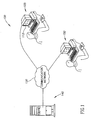
- Fig. 1 is a schematic illustration of an eye diagnosis system 100, in accordance with an example illustrating the invention.
- System 100 optionally includes a user terminal 105, which may be a general purpose computer used by a patient for various tasks, or may be dedicated for eye diagnosis.
- Terminal 105 includes a screen 112 on which patterns are displayed and one or more input devices through which patient indications are received, such as a keyboard and/or a mouse. Alternatively or additionally, other input devices may be used, such as a touch sensitive screen and/or a joystick.
- a server 140 transmits instructions to user terminal 105 on the patterns to be displayed and receives user responses from user terminal 105, for example through a communication network 130, e.g., the Internet. Based on the patient responses to the displayed patterns, server 140 calculates a map of the patient's eye and/or provides a diagnosis of the patient's eye, as described below in detail. Alternatively, some or all of the calculations are performed by user terminal 105.
- a physician terminal 150 close to server 140 or remote therefrom, is used by a physician to view the patient's eye map and/or to control the operation software of server 140.
- system 100 is shown as being distributed, such that user terminal 105 may be separated from server 140 by many miles, even thousands of miles, system 100 may be included in a single room and/or on a single computer, for example for patients that do not have home computers.
- terminal 105 instead of using terminal 105 other display units may be used, such as an eye projector, screens mounted on eye glasses, portable terminals or wide cinema screens.
- display units such as an eye projector, screens mounted on eye glasses, portable terminals or wide cinema screens.
- Fig. 2 is a flowchart of a mapping procedure of an eye.
- the patient performs the test procedure with one eye covered. Further optionally after a first eye is tested, the second eye is tested, if necessary.
- a plurality of patterns with a distortion are displayed (202) on screen 112.
- the stimuli are displayed for short durations up to about 400 milliseconds, for example between about 100-200 milliseconds.
- the patient is requested to indicate (203) the location of the distortion.
- the results for each pattern are optionally summarized (205) by the location of the distortion, the magnitude of the distortion and the location indicated by the patient.
- the location indications are spatially adjusted (204) in order to correct for persistent errors in the patient's pointing, perception and/or other non-eye mechanisms.
- a record is kept of distortions for which no response was received.
- the number of distortions for which patient indications were not received is optionally used in determining the reliability of the test.
- distortions for which patient indications are not received are used in evaluating the areas of the displayed distortion as the distortions may not have been perceived by the patient due to a lesion, overlying the displayed distortion, on the patient's visual field.
- Each patient indication is given (206) a probability score indicative of the probability that the patient indication is indicative of impaired eye tissue and is not a correct indication of the location of the displayed distortion. Generally, if the patient indicates a position close to the actual distortion, the patient's indication is most probably indicative of healthy eye tissue as the patient identified the displayed distortion. If, however, the patient indicates a different position, the patient's eye may be impaired at the indicated location and therefore the patient did not identify the displayed distortion, which was overridden by a competing pathological stimulus caused by a retinal-related lesion.
- the patient indication is given (207) a severity score S, optionally as a function of the distortion size and the probability score. As the distortion is greater, the retinal lesion needs to be more severe in order to cause the patient to point in the wrong location.
- a map M2 indicative of the health of each point of the eye tissue of the patient based on the response of the patient to the displayed pattern is generated (208).
- An accumulative map M1 is calculated (210) based on the maps M2 of each of the patterns.
- a binary map M3, which indicates impaired areas on accumulative map M1 is generated (212).
- the binary map generally identifies (214) clusters of impaired eye tissue. Parameters of the impaired clusters are optionally determined (216) and the patient is classified (218) according to the cluster parameters.
- accumulative map M1 and/or a clustered variation thereof is displayed (220) for analysis.
- patterns on the screen optionally, in order to map the patient's visual field, patterns having distortions at different areas on the visual field are displayed to the patient. In addition, patterns with different magnitude of distortion are displayed. Each pattern is optionally represented by the location of the distortion relative to the center of the display (corresponding to the fovea) and the magnitude of the distortion.
- Fig. 3 is a schematic illustration of an exemplary pattern format 300 of the patterns displayed to a patient by system 100.
- Pattern format 300 comprises a fragmented line 302 formed of a plurality of squares 304, for example between about 10-30 squares (e.g., 27-29).
- the line 302 has fewer than 10 squares or more than 30 squares.
- a continuous line is used.
- One or more squares 306 (3 squares in Fig. 3 ) are displaced from line 302, so as to form a distortion 308.
- Line 302 optionally has a length which covers between about 10-20° (e.g., 14°) of the patient's visual field, when the patient is situated at a normal distance from screen 12, for example about 30-60 centimeters. It is noted, however, that the tests are valid even if the patient sits much closer to screen 112 or much farther from screen 112. In the following description, whenever a length or distance is stated in degrees it means that the length covers that angle on the patient's visual field under these conditions.
- line 302 is displaced from the center of the display, by different distances, so as to cover substantially the entire area covered by the display.
- line 302 is displaced from the center of the display by different distances up to about -7.0° to 7.0°, depending on the size of the mapped visual field. In larger visual fields larger distances from the center may be used. It is also noted that non-symmetrical distances from the center may be mapped.
- the different patterns displayed to the patient optionally further differ in the distance (indicated by an arrow 310) between distortion 308 and line 302.
- the distances 310 of the different patterns are optionally between a maximal distance and a minimal distance.
- the maximal distance is optionally selected as a distance close to a value so large that it will be identified even by patients with severe lesions. Using larger distances will generally not add information on the patient's visual field.
- the minimal distance is optionally selected as a distance close to a distortion level that will not be identified by substantially all patients and therefore does not add information on the patient's visual field.
- the distances 310 used are between about 0.1°-0.35°, although other distances may be used, including distances even up to about 0.8° - 2.0° and more.
- the different patterns optionally differ in their orientation.
- line 302 is horizontal and in other patterns line 302 is vertical.
- diagonal patterns may be used.
- the squares 306 forming distortion 308 are optionally curved in the direction opposite the fovea, such that the central square 306 is farther from the fovea than the side squares 306.
- This distortion direction is similar to the pathological distortion of AMD patients.
- other shaped distortions are used, including distortions in the direction of the fovea.
- Fig. 4 is a schematic illustration of distortion positions in patterns displayed to a patient in a test session, in accordance with an example illustrating the invention. It is noted that only a single distortion is displayed at a single time. For clarity, only the distortions are shown, while lines 302 ( Fig. 3 ) are not shown in Fig. 4 . A sufficient number of patterns is used in order to cover substantially the entire visual field of the patient in a relatively even distribution.
- the patterns of Fig. 4 are brought by way of example and substantially any other set of patterns may be used. Optionally, the same set of patterns is used in all tests. Alternatively, different sets of patterns are used for different patients, for different eyes and/or at different times. Further optionally, the set of patterns used are selected randomly according to predetermined parameters.
- the patterns are displayed in a random order, for example in order to prevent patients from memorizing the answers of the test.
- the patterns are displayed in an order which begins with distortions which are easier to identify.
- horizontal patterns are displayed before vertical patterns, as most patients detect horizontal patterns more easily.
- the patterns are optionally ordered in a manner which minimizes the number of changes between substantially different patterns, for example between horizontal and vertical patterns.
- the patterns are arranged in a manner which allows collecting a sufficient amount of data in a first portion of the test session, and continuing to a second portion of the test session only if the early results are non-conclusive.
- the patterns are displayed in an order determined according to any other known considerations of psychophysical tests.
- pattern format 300 The details of pattern format 300 were presented for illustration purposes and various changes may be made in the pattern format, including the shapes forming line 302, the length of the line and the shape of the distortion. Another option is using short lines of 1°-10°, or long lines of 20°-90°. Optionally, tests are performed even with lines longer than 90° or even longer than 110°. Alternatively or additionally to patterns according to the pattern format in Fig. 3 , any other patterns, with or without distortions, may be used, for example the patterns described in US patent 6,656,131 and/or in PCT patent application PCT/IL03/00135 . These references also describe various alternatives to the details of pattern format 300, which may be used in accordance with the invention.
- the patterns are optionally displayed for a short period, in a manner which requires the patient to use different areas of the visual field in determining the location of the distortion.
- the view of the patient is fixated to the center of the display before each pattern is displayed, for example by displaying a slowly moving dot from the previously displayed distortion to the center of the display.
- a fixation point is displayed in the center of the display and the patient is instructed to fixate to the fixation point.
- any other fixation methods known in the art for fixating the patient to the center may be used.
- the displaying of the patterns and/or the reception of the indications is optionally performed using any of the embodiments in US patent 6,656,131 and/or in PCT patent application PCT/IL03/00135 .
- the score is a function of the probability that the patient did not identify the displayed distortion.
- the probability score is a function of the distance between the location of the patient indication and the location of the displayed distortion. This distance is referred to herein as the distance error.
- the probability score is a monotonous function, optionally a non-linear function, which increases with the error distance.
- system 100 is configured with a lower threshold L1 and an upper threshold L2. The thresholds are optionally configured such that distances below the lower threshold L1 are within a range of commonly made errors of pointing on a well identified distortion.
- the upper threshold is optionally set such that distances above the upper threshold L2 are only rarely (if at all) due to pointing at a well identified distortion.
- thresholds L1 and L2 are pre-configured based on tests on a relevant population. For example, L1 is set to 1.5° and L2 is set to 3°. Alternatively, L1 and L2 are adjusted based on the results of the current test. Optionally, L1 and L2 are adjusted according to a comparison of the patient indications to the displayed stimuli. According to the comparison, the error level of the patient is determined and L1 and L2 are set.
- L1 and L2 are configured according to preliminary tests performed on the specific patient.
- the values of thresholds L1 and L2 used for a specific patient are selected according to the type of pointing apparatus used by the patient and/or the age group (or other group) to which the patient belongs.
- the thresholds L1 and L2 are selected according to the specific tested eye, for example, whether the tested eye is the right or left eye of the patient, whether the tested eye is the dominant eye of the patient and/or whether the tested eye is the first or second eye tested in current session.
- the values of thresholds L1 and/or L2 are adjusted according to the distance from the fovea of the displayed distortion.
- a probability score of 0 is optionally assigned.
- a score of I is optionally assigned.
- the score optionally increases with the distance error.
- the patient may indicate a plurality of locations for a single stimulus.
- a predetermined threshold distance e.g., 0.5°
- the first or second indication is ignored.
- each of the indications is given only half the weight of a regular indication.
- each of the indications is given a weight larger than half the weight of a regular indication (for example, 0.7).
- indications which may be due to a mix up or other mistake are ignored or given low weight.
- indications close to the fovea when line 302 passes through the fovea are ignored to prevent mix up due to the fixation point.
- the severity score may also increase linearly with the probability score.
- the severity score increases linearly with the distortion size (ADH).
- ADH the distortion size
- the severity score is equal to the product of the distortion size and the probability score.
- any other function may be used in calculating the severity score, for example giving more weight to the distortion size.
- other factors are taken into account in generating the severity score, such as the area of the visual field in which the indicated location is situated. For example, distortions in the center of the visual field may be given extra weight in the severity score.
- the map is given a maximal distortion value at the location of the patient indication and lower values surrounding the patient indication location.
- the effect of the indication is spread over an area of the visual field of the patient.
- the map is given the severity score at the patient indication location and values decreasing monotonously with the distance, at the locations surrounding the patient indication location (x,y).
- R is the distance between the position (i,j) and a projection of the patient indication onto the line of displayed signal.
- other functions may be used, such as a polynomial decrease or a linear decrease.
- map M2 has a different size than a size of a grid on which the patient indication is received.
- the patient indications are optionally rescaled onto the grid of map M2, using methods known in the art.
- the Gaussian factor ⁇ is adjusted accordingly.
- the rescaling from a grid of 14 points to a grid of fifteen points is performed by multiplying by 50/14.
- an error vector representing the persistent error of the patient's indications may be determined and pattern map M2 may be generated accordingly.
- the error vector (x e ,y e ) is optionally determined by accumulating all the patient indications for which there is a high probability that the patient was pointing at the displayed distortion together with the respective locations of the displayed distortions. Alternatively, only some of the indications, most suitable for the calculation of the error vector, are used.
- L3 is adjusted according to the number of indications accumulated, such that the group of accumulated indications includes at least a minimal number of patient indications, for example at least 3-6 indications.
- the group of accumulated indications does not include at least a predetermined number of indications, no adjustment is performed for the persistent errors or additional data is collected so that there is sufficient data for the calculations.
- the additional data is optionally collected by performing a post-test in which easily identified stimuli are displayed.
- the error vector (x e , y e ) is optionally set as the difference between the average of the location of the accumulated indications and the average of the locations of their respective displayed distortions.
- a more complex average function may be used, such as an average which does not take into account outliers.
- the locations of the summarized (205) indications are adjusted (204) using the accumulated indications, for example using an affine transform or any other suitable transform which preserves the general spatial relation between the locations of the patient indications.
- a preliminary test session is carried out to determine the error vector of the persistent errors of the patient.
- the preliminary test session is optionally performed immediately before the actual test session, in order to have fresh error vector data.
- a single preliminary test session is performed for each patient periodically, in order not to add too much burden to the patient.
- patterns which are generally not affected by lesions in the visual field are displayed, for example relatively large patterns and/or patterns displayed for a relatively long duration. For example, dot sizes of about 0.4° are used in the preliminary test session.
- accumulative map M1 is initialized to zero at the beginning of each examination session.
- the accumulated map M1 is updated.
- the value of each pixel (i,j) is set to the sum of the previously accumulated value of the pixel M1(i,j) during the present testing session of the visual field and the value of the pixel in the current map M2(ij).
- the value of the accumulated map M1(i,j) is set to the severity score S.
- accumulative map M1 is generated after calculating all of maps M2 and each pixel of M1 is set to the sum of all the corresponding pixels of all of the maps M2 or to the highest severity score S of all the maps M2, whichever is higher.
- a threshold K defines a border between pixel values taken as representing healthy tissue and pixel values taken as representing impaired tissue.
- the binary map M3 has, without loss of generality, a "zero" value wherever accumulative map M1 has a value beneath threshold K and has a "one" value wherever accumulative map M1 has a value above threshold K.
- the value of threshold K is selected empirically based on tests in a plurality of patients.
- the value of threshold K may be selected based on a desired specificity-sensitivity working point.
- different thresholds K are used for different diseases and/or the specific classification desired.
- a lower threshold may be used for preliminary disease detection than for determination of a disease stage.
- different values for threshold K are used for patients with different attributes, for example different age groups and/or different disease history.
- threshold K is adjusted according to the specific eye of the patient, for example, left/right, first/second tested and/or dominant/non-dominant.
- a value of between 0.1 and 0.25 is used for K, optionally 0.15.
- a cluster map M4 is generated from binary map M3, using any clustering procedure known in the art, such as K-mean clustering methods and/or morphological image processing methods.
- K-mean clustering methods K-mean clustering methods
- morphological image processing methods e.g., a clustering method as described in above mentioned PCT application PCT/IL03/00135 is used, using a proximity criteria between each two points to determine whether they belong to a same cluster.
- a final test map M5 is optionally generated from accumulative map M1, masked by cluster map M4.
- the final test map M5 may receive the values of accumulative map M1 in those pixels belonging to a cluster in cluster map M4 or binary map M3, while the remaining pixels of final test map M5 are set to 0.
- Clustering map M4 optionally indicates for each pixel of accumulative map M1 and final test map M5, whether it belongs to a cluster and/or to which cluster it belongs.
- accumulative map M1 is optionally displayed.
- final map M5 which only shows clusters, is displayed.
- binary map M3 is displayed to give the physician a general view of the possibly afflicted areas.
- the displaying of non-binary maps is in accordance with a grayscale coding.
- the display uses any other color coding, for example using different colors for different score level ranges.
- the display may receive, for each pixel, a value selected from a multi-value scale including at least three, six, twenty or even above sixty values, allowing a physician to determine the extent and/or severity of the visual field defect at different map locations.
- the multi-value display scale includes 256 display levels.
- the final map is overlaid on an image of the eye or of other representations of the fundus.
- the displayed map is optionally used by a physician to assess the presence of visual field defects in the patient's visual field and the degree and spatial distribution of such defects.
- a physician may compared maps of the visual field of a patient acquired at different times in order to determine trends in progression of lesions in the visual field.
- the results of the tests in accordance with the present invention may be used together with other tests, such as direct eye examinations.
- automatic classification of the patient is performed, such that a trained physician is not required in order to provide a classification.
- the tests may be used on different classes of patients.
- the tests may be performed for AMD screening, for CNV detection or follow up, for example in patients known to have AMD and/or for post photo dynamic therapy (PDT), or any other therapy, follow up.
- PDT post photo dynamic therapy
- the tests may aid in determining if and when re-treatment is required.
- the tests may also be used for other retinal, chorioretinal and/or choroidal eye diseases, such as ocular hystoplasmosis, myopia, central serous retinopathy, central serous choroidopathy, glaucoma, diabetic retinopathy, media opacities (such as, but not limited to, cataract), retinitis pigmentosa, optic neuritis, epiretinal membrane, vascular abnormalities and/or occlusions, choroidal dystrophies, retinal dystrophies, macular hole, choroidal or retinal degeneration and/or lens abnormalities.
- ocular hystoplasmosis myopia
- central serous retinopathy central serous choroidopathy
- glaucoma glaucoma
- diabetic retinopathy media opacities (such as, but not limited to, cataract)
- retinitis pigmentosa optic neuritis, epiretinal membrane, vascular abnormalities and/or
- the display in addition to displaying the map (or instead of displaying the map), other information is displayed, such as the classification of the patient and/or the a confidence of the classification.
- the display includes patient identification information and/or patient medical history. Alternatively or additionally, any other information which may be useful is displayed.
- the intensity i.e., the score sum of all the pixels of the cluster
- the intensity of the cluster is determined by summing the scores of all the pixels classified as belonging to the cluster, in cluster map M4.
- the determined parameters include a maximal intensity (Imax) of any of the clusters.
- the maximal intensity (Imax) parameter is normalized to the area of the pixels of the cluster. The normalization is performed, for example, by multiplying the sum of the cluster having the highest score sum by a normalization factor ( ⁇ ) determined as the area of the eye represented by map M5 divided by the total number of pixels in map M5.
- the determined (216) parameters include the maximal area of any of the clusters (Amax), for example based on the number of pixels. Further alternatively or additionally, the determined (216) parameters include the maximal score value of a single pixel in the cluster having the largest intensity and/or the cluster having the largest area. Further alternatively or additionally, the determined (216) parameters include the area of the cluster having the greatest intensity and/or the intensity of the cluster having the greatest area. These parameters are indicative of the severity of the damage to a worst state cluster.
- the determined (216) parameters include the total area of the clusters in map M5 and/or the total number of the clusters.
- the parameters may be based on the spatial distribution of the clusters, for example, whether there is a cluster in the center and/or the size of such cluster and/or the shapes of the clusters (e.g., long and narrow or circular).
- the parameters include the width of a boundary area (i.e., an area in which the score is relatively close to the threshold K) of one or more of the clusters and/or a slope of a boundary area.
- Other parameters which may be used in the classification and/or displayed to the physician include average intensity, the location and/or value of the center of gravity of the cluster and/or the maximal intensity of the cluster.
- tests are optionally performed on a plurality of patients having clear-cut clinical classifications.
- a function which best correlates between the parameter values of the tested patients and their empirically determined classifications is determined.
- the patient is classified (218) based on applying the empirically determined function to the determined (216) parameters.
- the function is generated based on a best selection of sensitivity versus specificity, using any method known in the art. Alternatively, a relatively high specificity or a relatively high sensitivity is used, depending on the specific purpose of the test and/or on the identity of the patient.
- the function used in the classification depends also on external patient parameters, such as age, patient disease history, ethnic group and/or gender.
- the function used in the classification optionally depends on the eye being classified, for example whether the eye is the left or right eye, whether the eye is the first or second eye tested in a test session and/or whether the eye is the dominant eye of the patient.
- the dominant eye of the patient is optionally determined using any method known in the art or based on the dominant hand of the patient.
- the classification (218) is performed by comparing the value of one of the parameters to a threshold which best separates between patients of different classifications.
- Patients having a value equal or above 2 are classified as having CNV, while patients having a value beneath 2 are classified as having intermediate AMD (formerly generally referred to as HRC).
- HRC maximal cluster intensity parameter
- the classification may also be based on input from a physician viewing the displayed map.
- the map is displayed to a physician with the automatically generated classification and the physician may override the classification if necessary.
- system 100 automatically updates the functions it uses based on corrected classifications, periodically and/or in real time, using supervised or unsupervised learning.
- the classification is based on other parameters than Imax or Amax, for example any of the parameters mentioned above.
- the classification may be based on a comparison of results of a plurality of test sessions over time. For example, the currently determined map may be compared to a previously determined map to determine whether the disease has progressed or not.
- system 100 determines whether additional tests are needed and if so which tests are to be performed.
- the additional tests may be similar to the originally performed tests but with different parameter values.
- the additional tests may be concentrated in specific regions of the visual field of the patient.
- the additional tests may use different shapes of patterns, for example when the previously used pattern format did not provide conclusive results.
- the additional tests may relate to other areas of the eye which were not tested sufficiently. Table 1 Patient No.
- system 100 analyzes the test data of the patient in order to provide further testing and/or treatment related suggestions.
- the patient is tested a plurality of times and the results of the different tests are compared for the further testing and/or treatment related determination.
- system 100 suggests a time at which another test is to be performed.
- system 100 may automatically remind the patient to perform the tests and/or provides a physician with a list of patients that did not perform the tests on time.
- the next time to perform the test is optionally determined according to the rate of change from a previous test to the current test.
- the rate of change is optionally determined by determining a change amount divided by the time between the two tests. When the rate of change is relatively fast, more frequent test sessions are optionally suggested.
- the values of the cluster intensity parameter Imax from a plurality of test sessions of the eye is fit into a model of the expected behavior of the parameter over time.
- the parameter is expected to behave according to a parabolic model over time.
- the parameter first decreases and then begins to increase. Additional treatment is to be performed at the minimum of the parabola.
- an expected time at which the minimum will be reached is determined and accordingly a time for a next test session is set.
- a time at which the minimum will be or was reached is determined and accordingly a treatment session is set.
- the values of other parameters may be fit into the model.
- whether additional treatment is required is determined for the slope of the change of the parameter value.
- the type of treatment is determined.
- the tests may be used to determine whether to use laser treatment, PDT or drug injection.
- tests in accordance with the present invention may be relatively simple and optionally require only a few minutes (e.g., 5 minutes) per eye. Furthermore, the tests may be performed in a patient's home. The tests may be performed frequently, for example, every week or even every 2-3 days. Thus, the tests of the invention can be used for frequent monitoring of neovascular AMD patients, regardless of whether they underwent treatment.
- VA visual acuity
- FA fluorescein Angiography
- the results of the tests pre and post PDT treatment were compared.
- the FA test results were evaluated by a retina specialist.
- the PHP results were visually examined and the total area of the cluster(s) in the maps M5 were visually estimated. The results are given in TABLE 3.
- the results shown in TABLE 3 may be summarized as follows: In 7 patients (53% of total patient number), the PHP correlated with both FA and VA. In 4 patients (31%), the PHP correlated either with VA (in cases in which the FA results were stable) or with FA (in cases in which the VA results were stable). In 2 patients (16%) the PHP results showed improvement while VA and FA test results did not demonstrate any change.
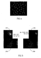
- Fig. 5 is a composite image illustrating PHP and FA test results of a patient, before and after PDT treatment. Images 352 and 354 show the final map M5 of the same patient taken before PDT treatment (image 352) and three months after the PDT treatment (354). Images 356 and 358 are corresponding FA photographs of the retina of the same tested eye taken before PDT treatment (356) and three months after the PDT treatment (358). The VA results for the same patient were 6/7.5 before PDT treatment and 6/6 after PDT treatment. Fig. 5 thus illustrates a good correlation between the FA, VA and PHP test results performed pre-PDT and post-PDT in the same eye.
- the PDT study results show a good correlation between the results of PHP, FA and VA tests. Furthermore, the results show a possibility that the PHP test is more sensitive than VA and FA for post-PDT changes.
- Fig. 6 shows a comparison of final maps M5 of seven patients, in tests performed before PDT treatment and six weeks after PDT treatment.
- a map 402 shows the test results before the PDT treatment
- a map 404 shows the test results six weeks after the PDT treatment, in the same eye.
- the maps 402 and 404 in columns 1 and 2 show improvement after the PDT treatment.
- the maps in columns 3, 4, 5 and 6 show deterioration after the PDT treatment and the maps in column 7 show stability. These maps show that the functionality of the patient's visual field may change within short periods.
- the functional testing of the present invention may offer in some cases, a better and more consistent resolution in time, than the anatomical FA test, known in the art.
- the patient indications indicate locations on a relatively large grid.
- the visual field is divided into a plurality of sectors and the score of each indication is accumulated in a sector score of the sector including the location of the received indication. Sectors having a high score are considered affected by a lesion.
- the patient is optionally classified according to a maximal sector score.
- the sectors have square or round shapes or other shapes that have close to equal width and length.
- the sectors have long and narrow shapes, such as rectangular strips.
- the sectors have triangular shapes, rings or circular sector shapes.
- each displayed stimulus includes a pattern with a visual distortion effecting the shape of the pattern. It is noted, however, that other defects in the pattern may be used including a gap (i.e., a missing portion) in the pattern, a color change in the pattern and/or a blurring of the pattern.
- additional stimuli may be used to further detract the patient from the pattern, and thus cause the patient to identify vision field lesions rather than the displayed defects. For example, a sound stimulus may be used for the detraction.
- stimuli to be identified themselves (not defects) by the patient are used.
- a stimulus is not identified by the patient, the location of the displayed stimulus is assumed to be defected.
- the test results are summarized by the amplitude of the displayed stimulus, the location of the displayed stimulus and whether the stimulus was identified by the patient.
- Fig. 2 may be performed for each patient indication upon reception of the indication, or may be performed after all the indications of a session or a portion of a session were received. It should be understood that features and/or steps described with respect to one example may be used with other examples and that not all embodiments of the invention have all of the features and/or steps shown in a particular figure or described with respect to one of the examples. Variations of examples described will occur to persons of the art.
Landscapes
- Health & Medical Sciences (AREA)
- Life Sciences & Earth Sciences (AREA)
- Engineering & Computer Science (AREA)
- Medical Informatics (AREA)
- Public Health (AREA)
- Biomedical Technology (AREA)
- General Health & Medical Sciences (AREA)
- Surgery (AREA)
- Veterinary Medicine (AREA)
- Molecular Biology (AREA)
- Physics & Mathematics (AREA)
- Animal Behavior & Ethology (AREA)
- Ophthalmology & Optometry (AREA)
- Biophysics (AREA)
- Heart & Thoracic Surgery (AREA)
- Data Mining & Analysis (AREA)
- Databases & Information Systems (AREA)
- Pathology (AREA)
- Epidemiology (AREA)
- Primary Health Care (AREA)
- Eye Examination Apparatus (AREA)
Claims (13)
- Vorrichtung zur Augendiagnose, mit:einer Anzeigeeinheit (105), um Muster auf eine Retina eines Patienten zu projizieren;einer Eingangsschnittstelle (105), um Angaben von einem Patienten in Reaktion auf die angezeigten Muster zu empfangen;einem Prozessor, der dazu ausgelegt ist, ein Kennfeld (M1-M5) des Gesichtsfeldes des Patienten in Reaktion auf Patientenangaben, die von der Eingangsschnittstelle (105) empfangen werden, die mit Orten wahrgenommener Formverzerrungen der angezeigten Muster in Beziehung stehen, zu erzeugen und in Reaktion auf das Kennfeld (M1-M5) zu bestimmen, ob der Patient eine bestimmte Stufe einer altersbezogenen Makulakrankheit, AMD, hat; undeiner Ausgangsschnittstelle (105, 150), um eine Altersangabe, die mit der Makuladegeneration eines Patienten in Beziehung steht, bereitzustellen,wobei der Prozessor dazu ausgelegt ist, für jede Angabe einen Abstand zwischen der Angabe und der entsprechenden angezeigten Verzerrung zu bestimmen,dadurch gekennzeichnet, dassder Prozessor ferner dazu ausgelegt ist, ein Gewicht bzw. eine Gewichtung spezifischer Angaben in dem erzeugten Kennfeld (M1-M5) in Übereinstimmung mit dem Abstand zwischen den Angaben und den angezeigten Verzerrungen zu bestimmen, unddass das Anzeigen der Muster mit Verzerrungen das Anzeigen von Verzerrungen unterschiedlicher Größen und das Verleihen einer höheren Gewichtung an Angaben, die größeren Defekten entsprechen, umfasst.
- Vorrichtung nach Anspruch 1, wobei die Anzeigeeinheit (105) einen Bildschirm (112) zum Anzeigen von Mustern für einen Patienten enthält.
- Vorrichtung nach Anspruch 1, wobei die Anzeigeeinheit (105) einen Augenprojektor zum Anzeigen von Mustern auf einem Auge eines Patienten enthält.
- Vorrichtung nach einem der vorhergehenden Ansprüche, wobei der Prozessor von der Eingangsschnittstelle (105) entfernt ist.
- Vorrichtung nach einem der vorhergehenden Ansprüche, wobei der Prozessor dazu ausgelegt ist, einen Cluster-Parameter eines Clusters in dem Kennfeld (M1-M5) zu bestimmen und den Patienten in Bezug auf eine Augenkrankheit wenigstens teilweise anhand des Cluster-Parameters zu klassifizieren.
- Vorrichtung nach einem der vorhergehenden Ansprüche, wobei der Prozessor dazu ausgelegt ist, das Kennfeld (M1-M5) anhand von Angaben, die in Reaktion auf mehrere angezeigte Muster mit mehreren verschiedenen Formen empfangen werden, zu erzeugen.
- Vorrichtung nach einem der vorhergehenden Ansprüche, wobei der Prozessor bei Erzeugung des Kennfeldes (M1-M5) in der Weise arbeitet, dass wenigstens einige der Angaben einen Bereich des Kennfeldes, der größer ist als der durch die Angabe abgedeckte Bereich, beeinflussen.
- Vorrichtung nach einem der vorhergehenden Ansprüche, wobei der Prozessor bei der Erzeugung des Kennfeldes (M1-M5) in der Weise arbeitet, dass wenigstens einige der Angaben mehrere Pixel in dem Kennfeld beeinflussen.
- Vorrichtung nach einem der vorhergehenden Ansprüche, wobei der Prozessor dazu ausgelegt ist, in dem erzeugten Kennfeld (M1-M5) wenigstens einen Cluster von Werten, die anomalem Gewebe entsprechen, zu bestimmen.
- Vorrichtung nach Anspruch 9, wobei wenigstens ein Cluster mehrere Cluster enthält, wobei ein größter Cluster der mehreren Cluster bestimmt wird.
- Vorrichtung nach Anspruch 10, wobei der Prozessor dazu ausgelegt ist, einen Parameter des größten Clusters zu bestimmen.
- Vorrichtung nach Anspruch 11, wobei der Prozessor dazu ausgelegt ist, einen größenbezogenen Parameter zu bestimmen, der von einem bei der Auswahl des größten Clusters verwendeten Parameter verschieden ist.
- Vorrichtung nach Anspruch 11, wobei der Prozessor dazu ausgelegt ist, einen größenbezogenen Parameter zu bestimmen, der bei der Auswahl des größten Clusters verwendet wird.
Applications Claiming Priority (2)
| Application Number | Priority Date | Filing Date | Title |
|---|---|---|---|
| US46756203P | 2003-05-05 | 2003-05-05 | |
| PCT/IL2004/000374 WO2004098447A2 (en) | 2003-05-05 | 2004-05-05 | Eye mapping |
Publications (3)
| Publication Number | Publication Date |
|---|---|
| EP1624794A2 EP1624794A2 (de) | 2006-02-15 |
| EP1624794A4 EP1624794A4 (de) | 2009-05-13 |
| EP1624794B1 true EP1624794B1 (de) | 2012-07-04 |
Family
ID=34115292
Family Applications (1)
| Application Number | Title | Priority Date | Filing Date |
|---|---|---|---|
| EP04731253A Expired - Lifetime EP1624794B1 (de) | 2003-05-05 | 2004-05-05 | Augenkartierung |
Country Status (3)
| Country | Link |
|---|---|
| US (1) | US7665847B2 (de) |
| EP (1) | EP1624794B1 (de) |
| WO (1) | WO2004098447A2 (de) |
Cited By (1)
| Publication number | Priority date | Publication date | Assignee | Title |
|---|---|---|---|---|
| WO2020139192A1 (en) * | 2018-12-27 | 2020-07-02 | Tan Tock Seng Hospital Pte Ltd | System, method and apparatus for detecting an eye condition |
Families Citing this family (38)
| Publication number | Priority date | Publication date | Assignee | Title |
|---|---|---|---|---|
| US7740592B2 (en) * | 2000-04-17 | 2010-06-22 | The University Of Sydney | Method and apparatus for objective electrophysiological assessment of visual function |
| US7753524B2 (en) * | 2002-02-08 | 2010-07-13 | Novavision, Inc. | Process and device for treating blind regions of the visual field |
| US7682021B2 (en) * | 2002-02-08 | 2010-03-23 | Novavision, Inc. | System and methods for the treatment of retinal diseases |
| US20070216865A1 (en) * | 2002-02-08 | 2007-09-20 | Novavision, Inc. | Process and Device for Apportioning Therapeutic Vision Stimuli |
| WO2006002070A2 (en) | 2004-06-15 | 2006-01-05 | Novavision, Inc. | Method and device for guiding a user's head during vision training |
| EP1869521A1 (de) * | 2005-03-30 | 2007-12-26 | Novavision, Inc. | Verfahren und vorrichtung zur freisetzung visueller stimuli mit kopfmontierter anzeige während eines visionstrainings |
| US8668334B2 (en) | 2006-02-27 | 2014-03-11 | Vital Art And Science Incorporated | Vision measurement and training system and method of operation thereof |
| JP2009542368A (ja) * | 2006-06-30 | 2009-12-03 | ノバビジョン, インコーポレイテッド | 偏心視の診断および治療システム |
| US8029138B2 (en) | 2006-07-25 | 2011-10-04 | Novavision, Inc. | Dynamic peripheral stimuli for visual field testing and therapy |
| US8226237B2 (en) | 2006-09-28 | 2012-07-24 | Reichert, Inc. | Apparatus and method for monitoring the position of a subject's hand |
| US8079710B2 (en) * | 2008-01-10 | 2011-12-20 | Notal Vision Ltd. | Dual position ophthalmic apparatus |
| PT2427095T (pt) * | 2009-05-09 | 2023-10-13 | Genentech Inc | Sistema de avaliação e rastreio de visão de descriminação de forma |
| WO2010132305A1 (en) | 2009-05-09 | 2010-11-18 | Vital Art And Science Incorporated | Handheld vision tester and calibration thereof |
| WO2010134889A1 (en) * | 2009-05-19 | 2010-11-25 | Singapore Health Services Pte Ltd | Methods and systems for pathological myopia detection |
| US8534839B2 (en) | 2010-03-01 | 2013-09-17 | Alcon Research, Ltd. | Adaptive visual performance testing system |
| US9380938B2 (en) | 2011-09-08 | 2016-07-05 | Gobiquity, Inc. | System and methods for documenting and recording of the pupillary red reflex test and corneal light reflex screening of the eye in infants and young children |
| WO2013059331A1 (en) | 2011-10-17 | 2013-04-25 | Digisight Technologies, Inc. | System and method for providing analysis of visual function using a mobile device with display |
| US9462941B2 (en) | 2011-10-17 | 2016-10-11 | The Board Of Trustees Of The Leland Stanford Junior University | Metamorphopsia testing and related methods |
| US9433346B2 (en) | 2011-11-21 | 2016-09-06 | Gobiquity, Inc. | Circular preferential hyperacuity perimetry video game to monitor macular and retinal diseases |
| JP2014533587A (ja) | 2011-11-21 | 2014-12-15 | アイチェック ヘルス コネクション, インコーポレイテッド | 網膜疾患を監視するビデオゲーム |
| US9629538B2 (en) | 2013-04-26 | 2017-04-25 | Vital Art And Science, Llc | Contour integration perimetry vision test |
| WO2016095062A1 (de) * | 2014-12-19 | 2016-06-23 | Haag-Streit Ag | Kinetische perimetrie |
| US12237074B2 (en) * | 2015-03-17 | 2025-02-25 | Raytrx, Llc | System, method, and non-transitory computer-readable storage media related to correction of vision defects using a visual display |
| US11016302B2 (en) | 2015-03-17 | 2021-05-25 | Raytrx, Llc | Wearable image manipulation and control system with high resolution micro-displays and dynamic opacity augmentation in augmented reality glasses |
| US11956414B2 (en) | 2015-03-17 | 2024-04-09 | Raytrx, Llc | Wearable image manipulation and control system with correction for vision defects and augmentation of vision and sensing |
| WO2016149536A1 (en) | 2015-03-17 | 2016-09-22 | Ocutrx Vision Technologies, Llc. | Correction of vision defects using a visual display |
| US11628038B2 (en) | 2020-02-21 | 2023-04-18 | Raytrx, Llc | Multi-option all-digital 3D surgery visualization system and control |
| US11461936B2 (en) | 2015-03-17 | 2022-10-04 | Raytrx, Llc | Wearable image manipulation and control system with micro-displays and augmentation of vision and sensing in augmented reality glasses |
| US20180014724A1 (en) * | 2016-07-18 | 2018-01-18 | Dariusz Wroblewski | Method and System for Analysis of Diagnostic Parameters and Disease Progression |
| WO2018025125A1 (en) * | 2016-07-31 | 2018-02-08 | Ic Inside Ltd. | Method of retinal sensitivity mapping using near-eye display |
| WO2019108916A1 (en) * | 2017-11-30 | 2019-06-06 | Ohio State Innovation Foundation | Method and system for measuring or assessing human visual field |
| US10413172B2 (en) | 2017-12-11 | 2019-09-17 | 1-800 Contacts, Inc. | Digital visual acuity eye examination for remote physician assessment |
| EP3758576A4 (de) * | 2018-03-02 | 2022-03-09 | Ohio State Innovation Foundation | Systeme und verfahren zur messung von visuellen funktionskarten |
| AU2019208212B2 (en) * | 2018-07-27 | 2025-02-27 | Welch Allyn, Inc. | Vision screening device and methods |
| US12142367B2 (en) | 2020-02-21 | 2024-11-12 | Raytrx, Llc | Surgery visualization theatre |
| KR102232925B1 (ko) * | 2020-03-13 | 2021-03-26 | 재단법인 아산사회복지재단 | 시야 결손 치료 장치 및 시야 결손 치료 방법 |
| CA3197759A1 (en) | 2020-10-08 | 2022-04-14 | Notal Vision Ltd. | Oct guided therapy |
| WO2024069454A1 (en) * | 2022-09-28 | 2024-04-04 | Notal Vision Ltd. | Methods and systems for detecting risk for development of a retinal condition using visual field tests |
Family Cites Families (33)
| Publication number | Priority date | Publication date | Assignee | Title |
|---|---|---|---|---|
| US3883235A (en) * | 1971-09-17 | 1975-05-13 | John R Lynn | Automatic visual field examination including fixation monitoring compensation |
| JPS54136792A (en) | 1978-04-11 | 1979-10-24 | Rodenstock Optik G | Method of measuring human eye dynamic or static visual field |
| US4634243A (en) | 1984-12-26 | 1987-01-06 | Lkc Systems, Inc. | Glaucoma detection utilizing pattern discrimination test |
| US4798456A (en) | 1987-03-23 | 1989-01-17 | The Regents Of The University Of California | Method for evaluating metamorphopsia |
| US4822162A (en) | 1987-08-27 | 1989-04-18 | Richardson Robert W | Method and device for measuring retinal response as a function of position of the retina |
| US5061060A (en) | 1987-09-18 | 1991-10-29 | Oculus Optikgeraete Gmbh | Apparatus and method for finding of scotomas in the eye of a person tested |
| US4995717A (en) | 1989-08-22 | 1991-02-26 | The University Court Of The University Of Glasgow | Device for moving eye campimetry |
| US5412561A (en) | 1992-01-28 | 1995-05-02 | Rosenshein; Joseph S. | Method of analysis of serial visual fields |
| US5539482A (en) | 1992-02-28 | 1996-07-23 | The Australian National University | Glaucoma testing using non-linear systems identification techniques |
| US5382987A (en) | 1992-05-22 | 1995-01-17 | Board Of Regents, The University Of Texas System | Device for ERG spectral perimetry |
| JP3317754B2 (ja) * | 1993-09-16 | 2002-08-26 | 株式会社トプコン | 視野測定装置 |
| US5589897A (en) | 1995-05-01 | 1996-12-31 | Stephen H. Sinclair | Method and apparatus for central visual field mapping and optimization of image presentation based upon mapped parameters |
| US5565949A (en) | 1995-07-10 | 1996-10-15 | Kasha, Jr.; John R. | Visual field perimetry on a small computer screen |
| US5946075A (en) | 1996-05-21 | 1999-08-31 | Horn; Gerald | Vision screening system |
| US5864384A (en) | 1996-07-31 | 1999-01-26 | Mcclure; Richard J. | Visual field testing method and apparatus using virtual reality |
| US6027217A (en) * | 1996-07-31 | 2000-02-22 | Virtual-Eye.Com, Inc. | Automated visual function testing via telemedicine |
| US6033076A (en) | 1996-07-31 | 2000-03-07 | Virtual-Eye.Com, Inc. | Visual field testing via telemedicine |
| US5883692A (en) | 1997-10-01 | 1999-03-16 | Retsan, Inc. | Visual field measurement apparatus |
| US5892570A (en) | 1997-11-24 | 1999-04-06 | State Of Oregon Acting By And Through The State Board Of Higher Education On Behalf Of The University Of Oregon | Method and apparatus for measuring and correcting metamorphopsia |
| IL125483A (en) | 1998-07-23 | 2006-08-20 | Talia Technologia Ltd | System and method for acquiring, analyzing and imaging of three dimensional retinal data |
| AU761527B2 (en) | 1998-12-30 | 2003-06-05 | Boel Bengtsson | A method and an apparatus for performing a visual field test, and computer programs for processing the results thereof |
| DE60008827T2 (de) | 1999-09-17 | 2004-08-12 | Inami & Co. Ltd. | Testkarten für Metamorphopsie |
| US6688746B2 (en) | 1999-12-03 | 2004-02-10 | Iouri Malov | Field testing using spread spectrum technique |
| AU2001247830A1 (en) * | 2000-03-27 | 2001-10-08 | California Institute Of Technology | Computer-based 3d visual field test system and analysis |
| US6513931B1 (en) | 2000-05-31 | 2003-02-04 | Prio Corporation | Method and apparatus for testing the vision of a video display terminal user |
| US6494578B1 (en) | 2000-07-13 | 2002-12-17 | The Regents Of The University Of California | Virtual reality peripheral vision scotoma screening |
| IL138926A0 (en) | 2000-10-06 | 2001-11-25 | Notal Vision Ltd | Method and system for detecting eye disease |
| US6406437B1 (en) * | 2000-10-11 | 2002-06-18 | Yeda Research And Development Co. Ltd. | Method and apparatus for efficient high-resolution visual field mapping |
| US6572229B2 (en) | 2001-06-14 | 2003-06-03 | Carl Zeiss, Inc. | Back projection visual field tester |
| US7155393B2 (en) * | 2001-08-18 | 2006-12-26 | Visionrx, Llc | Method for establishing fixation employing speech recognition |
| US6742894B2 (en) * | 2001-10-01 | 2004-06-01 | Visionrx, Inc. | System and method for full field oscillating stimulus perimeter |
| US6572753B2 (en) * | 2001-10-01 | 2003-06-03 | Eci Technology, Inc. | Method for analysis of three organic additives in an acid copper plating bath |
| WO2003070089A1 (en) * | 2002-02-19 | 2003-08-28 | Notal Vision Ltd. | Method and system for assessing eye disease |
-
2004
- 2004-05-05 EP EP04731253A patent/EP1624794B1/de not_active Expired - Lifetime
- 2004-05-05 US US10/556,146 patent/US7665847B2/en not_active Expired - Lifetime
- 2004-05-05 WO PCT/IL2004/000374 patent/WO2004098447A2/en not_active Ceased
Cited By (1)
| Publication number | Priority date | Publication date | Assignee | Title |
|---|---|---|---|---|
| WO2020139192A1 (en) * | 2018-12-27 | 2020-07-02 | Tan Tock Seng Hospital Pte Ltd | System, method and apparatus for detecting an eye condition |
Also Published As
| Publication number | Publication date |
|---|---|
| US7665847B2 (en) | 2010-02-23 |
| WO2004098447A2 (en) | 2004-11-18 |
| US20070121070A1 (en) | 2007-05-31 |
| EP1624794A4 (de) | 2009-05-13 |
| EP1624794A2 (de) | 2006-02-15 |
| WO2004098447A3 (en) | 2005-02-10 |
Similar Documents
| Publication | Publication Date | Title |
|---|---|---|
| EP1624794B1 (de) | Augenkartierung | |
| EP1485006B1 (de) | System zur untersuchung von augenerkrankungen | |
| US7275830B2 (en) | Methods devices and systems for detecting eye disease | |
| US10925481B2 (en) | Systems and methods for measuring visual function maps | |
| Maddess et al. | Testing for glaucoma with the spatial frequency doubling illusion | |
| CN100544666C (zh) | 视力测试系统 | |
| EP2922461B1 (de) | Geclustertes abgabeverfahren und vorrichtung | |
| EP2265328B1 (de) | Apparat für die automatische anpassung einer therapie nach dysfunktion des nervensystems | |
| CN112168135B (zh) | 基于人工智能的眼球疾病诊断装置及方法 | |
| US10638925B2 (en) | Determining vision related physical conditions from cross-parameter vision tests | |
| AU2002210874A2 (en) | Methods devices and systems for detecting eye disease | |
| AU2002210874A1 (en) | Methods devices and systems for detecting eye disease | |
| AU2005221167A1 (en) | Apparatus and method for assessing retinal damage | |
| US20210391056A1 (en) | Health big data service method and system based on remote fundus screening | |
| EP3402388B1 (de) | System und verfahren zur durchführung von objektiver perimetrie und diagnose von patienten mit retinitis pigmentosa und anderen augenerkrankungen | |
| WO2023044520A1 (en) | Methods and systems for screening for central visual field loss | |
| US20250213108A1 (en) | Methods and Systems for Detecting Risk for Development of a Retinal Condition Using Visual Field Tests | |
| Thurman et al. | Multi-line Adaptive Perimetry (MAP): A New Procedure for Quantifying Visual Field Integrity for Rapid Assessment of Macular Diseases | |
| Brito | Age-related changes in the detection and classification of motion in the periphery of the visual field | |
| Sood | Basic Perimetry |
Legal Events
| Date | Code | Title | Description |
|---|---|---|---|
| PUAI | Public reference made under article 153(3) epc to a published international application that has entered the european phase |
Free format text: ORIGINAL CODE: 0009012 |
|
| 17P | Request for examination filed |
Effective date: 20051205 |
|
| AK | Designated contracting states |
Kind code of ref document: A2 Designated state(s): AT BE BG CH CY CZ DE DK EE ES FI FR GB GR HU IE IT LI LU MC NL PL PT RO SE SI SK TR |
|
| DAX | Request for extension of the european patent (deleted) | ||
| A4 | Supplementary search report drawn up and despatched |
Effective date: 20090414 |
|
| 17Q | First examination report despatched |
Effective date: 20090806 |
|
| RAP1 | Party data changed (applicant data changed or rights of an application transferred) |
Owner name: REICHERT, INC. |
|
| REG | Reference to a national code |
Ref country code: DE Ref legal event code: R079 Ref document number: 602004038437 Country of ref document: DE Free format text: PREVIOUS MAIN CLASS: A61B0003020000 Ipc: A61B0003024000 |
|
| RIC1 | Information provided on ipc code assigned before grant |
Ipc: A61B 3/024 20060101AFI20111130BHEP Ipc: A61B 3/032 20060101ALI20111130BHEP |
|
| GRAP | Despatch of communication of intention to grant a patent |
Free format text: ORIGINAL CODE: EPIDOSNIGR1 |
|
| RIN1 | Information on inventor provided before grant (corrected) |
Inventor name: ELIKHIS, EDWARD Inventor name: RAFAELI, OMER Inventor name: ALSTER, YAIR |
|
| GRAS | Grant fee paid |
Free format text: ORIGINAL CODE: EPIDOSNIGR3 |
|
| GRAA | (expected) grant |
Free format text: ORIGINAL CODE: 0009210 |
|
| AK | Designated contracting states |
Kind code of ref document: B1 Designated state(s): AT BE BG CH CY CZ DE DK EE ES FI FR GB GR HU IE IT LI LU MC NL PL PT RO SE SI SK TR |
|
| REG | Reference to a national code |
Ref country code: GB Ref legal event code: FG4D |
|
| REG | Reference to a national code |
Ref country code: DE Ref legal event code: R081 Ref document number: 602004038437 Country of ref document: DE Owner name: NOTAL VISION LTD., IL Free format text: FORMER OWNER: NOTAL VISION LTD., TEL AVIV, IL |
|
| REG | Reference to a national code |
Ref country code: CH Ref legal event code: EP |
|
| REG | Reference to a national code |
Ref country code: AT Ref legal event code: REF Ref document number: 564802 Country of ref document: AT Kind code of ref document: T Effective date: 20120715 |
|
| REG | Reference to a national code |
Ref country code: IE Ref legal event code: FG4D |
|
| REG | Reference to a national code |
Ref country code: DE Ref legal event code: R096 Ref document number: 602004038437 Country of ref document: DE Effective date: 20120830 |
|
| REG | Reference to a national code |
Ref country code: AT Ref legal event code: MK05 Ref document number: 564802 Country of ref document: AT Kind code of ref document: T Effective date: 20120704 |
|
| REG | Reference to a national code |
Ref country code: NL Ref legal event code: VDEP Effective date: 20120704 |
|
| PG25 | Lapsed in a contracting state [announced via postgrant information from national office to epo] |
Ref country code: SI Free format text: LAPSE BECAUSE OF FAILURE TO SUBMIT A TRANSLATION OF THE DESCRIPTION OR TO PAY THE FEE WITHIN THE PRESCRIBED TIME-LIMIT Effective date: 20120704 |
|
| PG25 | Lapsed in a contracting state [announced via postgrant information from national office to epo] |
Ref country code: BE Free format text: LAPSE BECAUSE OF FAILURE TO SUBMIT A TRANSLATION OF THE DESCRIPTION OR TO PAY THE FEE WITHIN THE PRESCRIBED TIME-LIMIT Effective date: 20120704 Ref country code: AT Free format text: LAPSE BECAUSE OF FAILURE TO SUBMIT A TRANSLATION OF THE DESCRIPTION OR TO PAY THE FEE WITHIN THE PRESCRIBED TIME-LIMIT Effective date: 20120704 Ref country code: CY Free format text: LAPSE BECAUSE OF FAILURE TO SUBMIT A TRANSLATION OF THE DESCRIPTION OR TO PAY THE FEE WITHIN THE PRESCRIBED TIME-LIMIT Effective date: 20120704 Ref country code: FI Free format text: LAPSE BECAUSE OF FAILURE TO SUBMIT A TRANSLATION OF THE DESCRIPTION OR TO PAY THE FEE WITHIN THE PRESCRIBED TIME-LIMIT Effective date: 20120704 |
|
| PG25 | Lapsed in a contracting state [announced via postgrant information from national office to epo] |
Ref country code: PL Free format text: LAPSE BECAUSE OF FAILURE TO SUBMIT A TRANSLATION OF THE DESCRIPTION OR TO PAY THE FEE WITHIN THE PRESCRIBED TIME-LIMIT Effective date: 20120704 Ref country code: GR Free format text: LAPSE BECAUSE OF FAILURE TO SUBMIT A TRANSLATION OF THE DESCRIPTION OR TO PAY THE FEE WITHIN THE PRESCRIBED TIME-LIMIT Effective date: 20121005 Ref country code: PT Free format text: LAPSE BECAUSE OF FAILURE TO SUBMIT A TRANSLATION OF THE DESCRIPTION OR TO PAY THE FEE WITHIN THE PRESCRIBED TIME-LIMIT Effective date: 20121105 Ref country code: SE Free format text: LAPSE BECAUSE OF FAILURE TO SUBMIT A TRANSLATION OF THE DESCRIPTION OR TO PAY THE FEE WITHIN THE PRESCRIBED TIME-LIMIT Effective date: 20120704 |
|
| PG25 | Lapsed in a contracting state [announced via postgrant information from national office to epo] |
Ref country code: NL Free format text: LAPSE BECAUSE OF FAILURE TO SUBMIT A TRANSLATION OF THE DESCRIPTION OR TO PAY THE FEE WITHIN THE PRESCRIBED TIME-LIMIT Effective date: 20120704 |
|
| PG25 | Lapsed in a contracting state [announced via postgrant information from national office to epo] |
Ref country code: EE Free format text: LAPSE BECAUSE OF FAILURE TO SUBMIT A TRANSLATION OF THE DESCRIPTION OR TO PAY THE FEE WITHIN THE PRESCRIBED TIME-LIMIT Effective date: 20120704 Ref country code: CZ Free format text: LAPSE BECAUSE OF FAILURE TO SUBMIT A TRANSLATION OF THE DESCRIPTION OR TO PAY THE FEE WITHIN THE PRESCRIBED TIME-LIMIT Effective date: 20120704 Ref country code: DK Free format text: LAPSE BECAUSE OF FAILURE TO SUBMIT A TRANSLATION OF THE DESCRIPTION OR TO PAY THE FEE WITHIN THE PRESCRIBED TIME-LIMIT Effective date: 20120704 Ref country code: ES Free format text: LAPSE BECAUSE OF FAILURE TO SUBMIT A TRANSLATION OF THE DESCRIPTION OR TO PAY THE FEE WITHIN THE PRESCRIBED TIME-LIMIT Effective date: 20121015 Ref country code: RO Free format text: LAPSE BECAUSE OF FAILURE TO SUBMIT A TRANSLATION OF THE DESCRIPTION OR TO PAY THE FEE WITHIN THE PRESCRIBED TIME-LIMIT Effective date: 20120704 |
|
| PLBE | No opposition filed within time limit |
Free format text: ORIGINAL CODE: 0009261 |
|
| STAA | Information on the status of an ep patent application or granted ep patent |
Free format text: STATUS: NO OPPOSITION FILED WITHIN TIME LIMIT |
|
| PG25 | Lapsed in a contracting state [announced via postgrant information from national office to epo] |
Ref country code: SK Free format text: LAPSE BECAUSE OF FAILURE TO SUBMIT A TRANSLATION OF THE DESCRIPTION OR TO PAY THE FEE WITHIN THE PRESCRIBED TIME-LIMIT Effective date: 20120704 Ref country code: IT Free format text: LAPSE BECAUSE OF FAILURE TO SUBMIT A TRANSLATION OF THE DESCRIPTION OR TO PAY THE FEE WITHIN THE PRESCRIBED TIME-LIMIT Effective date: 20120704 |
|
| 26N | No opposition filed |
Effective date: 20130405 |
|
| PG25 | Lapsed in a contracting state [announced via postgrant information from national office to epo] |
Ref country code: BG Free format text: LAPSE BECAUSE OF FAILURE TO SUBMIT A TRANSLATION OF THE DESCRIPTION OR TO PAY THE FEE WITHIN THE PRESCRIBED TIME-LIMIT Effective date: 20121004 |
|
| REG | Reference to a national code |
Ref country code: DE Ref legal event code: R097 Ref document number: 602004038437 Country of ref document: DE Effective date: 20130405 |
|
| PG25 | Lapsed in a contracting state [announced via postgrant information from national office to epo] |
Ref country code: MC Free format text: LAPSE BECAUSE OF FAILURE TO SUBMIT A TRANSLATION OF THE DESCRIPTION OR TO PAY THE FEE WITHIN THE PRESCRIBED TIME-LIMIT Effective date: 20120704 |
|
| REG | Reference to a national code |
Ref country code: CH Ref legal event code: PL |
|
| PG25 | Lapsed in a contracting state [announced via postgrant information from national office to epo] |
Ref country code: CH Free format text: LAPSE BECAUSE OF NON-PAYMENT OF DUE FEES Effective date: 20130531 Ref country code: LI Free format text: LAPSE BECAUSE OF NON-PAYMENT OF DUE FEES Effective date: 20130531 |
|
| REG | Reference to a national code |
Ref country code: IE Ref legal event code: MM4A |
|
| PG25 | Lapsed in a contracting state [announced via postgrant information from national office to epo] |
Ref country code: IE Free format text: LAPSE BECAUSE OF NON-PAYMENT OF DUE FEES Effective date: 20130505 |
|
| REG | Reference to a national code |
Ref country code: FR Ref legal event code: PLFP Year of fee payment: 12 |
|
| REG | Reference to a national code |
Ref country code: DE Ref legal event code: R082 Ref document number: 602004038437 Country of ref document: DE Representative=s name: HOEGER, STELLRECHT & PARTNER PATENTANWAELTE, DE Ref country code: DE Ref legal event code: R081 Ref document number: 602004038437 Country of ref document: DE Owner name: NOTAL VISION LTD., IL Free format text: FORMER OWNER: REICHERT, INC., DEPEW, N.Y., US Ref country code: DE Ref legal event code: R082 Ref document number: 602004038437 Country of ref document: DE Representative=s name: HOEGER, STELLRECHT & PARTNER PATENTANWAELTE MB, DE |
|
| REG | Reference to a national code |
Ref country code: GB Ref legal event code: 732E Free format text: REGISTERED BETWEEN 20150521 AND 20150527 |
|
| PG25 | Lapsed in a contracting state [announced via postgrant information from national office to epo] |
Ref country code: TR Free format text: LAPSE BECAUSE OF FAILURE TO SUBMIT A TRANSLATION OF THE DESCRIPTION OR TO PAY THE FEE WITHIN THE PRESCRIBED TIME-LIMIT Effective date: 20120704 |
|
| REG | Reference to a national code |
Ref country code: DE Ref legal event code: R082 Ref document number: 602004038437 Country of ref document: DE Representative=s name: HOEGER, STELLRECHT & PARTNER PATENTANWAELTE MB, DE |
|
| PG25 | Lapsed in a contracting state [announced via postgrant information from national office to epo] |
Ref country code: HU Free format text: LAPSE BECAUSE OF FAILURE TO SUBMIT A TRANSLATION OF THE DESCRIPTION OR TO PAY THE FEE WITHIN THE PRESCRIBED TIME-LIMIT; INVALID AB INITIO Effective date: 20040505 Ref country code: LU Free format text: LAPSE BECAUSE OF NON-PAYMENT OF DUE FEES Effective date: 20130505 |
|
| REG | Reference to a national code |
Ref country code: FR Ref legal event code: TP Owner name: NOTAL VISION LTD., IL Effective date: 20150811 |
|
| REG | Reference to a national code |
Ref country code: FR Ref legal event code: PLFP Year of fee payment: 13 |
|
| REG | Reference to a national code |
Ref country code: FR Ref legal event code: PLFP Year of fee payment: 14 |
|
| REG | Reference to a national code |
Ref country code: FR Ref legal event code: PLFP Year of fee payment: 15 |
|
| REG | Reference to a national code |
Ref country code: DE Ref legal event code: R082 Ref document number: 602004038437 Country of ref document: DE Representative=s name: HOEGER, STELLRECHT & PARTNER PATENTANWAELTE MB, DE |
|
| PGFP | Annual fee paid to national office [announced via postgrant information from national office to epo] |
Ref country code: FR Payment date: 20230525 Year of fee payment: 20 Ref country code: DE Payment date: 20220620 Year of fee payment: 20 |
|
| PGFP | Annual fee paid to national office [announced via postgrant information from national office to epo] |
Ref country code: GB Payment date: 20230523 Year of fee payment: 20 |
|
| REG | Reference to a national code |
Ref country code: DE Ref legal event code: R071 Ref document number: 602004038437 Country of ref document: DE |
|
| REG | Reference to a national code |
Ref country code: GB Ref legal event code: PE20 Expiry date: 20240504 |
|
| PG25 | Lapsed in a contracting state [announced via postgrant information from national office to epo] |
Ref country code: GB Free format text: LAPSE BECAUSE OF EXPIRATION OF PROTECTION Effective date: 20240504 |
|
| PG25 | Lapsed in a contracting state [announced via postgrant information from national office to epo] |
Ref country code: GB Free format text: LAPSE BECAUSE OF EXPIRATION OF PROTECTION Effective date: 20240504 |