EP1624955B1 - Flüssigkeitmischvorrichtung für geschlossene behälter - Google Patents
Flüssigkeitmischvorrichtung für geschlossene behälter Download PDFInfo
- Publication number
- EP1624955B1 EP1624955B1 EP04731867A EP04731867A EP1624955B1 EP 1624955 B1 EP1624955 B1 EP 1624955B1 EP 04731867 A EP04731867 A EP 04731867A EP 04731867 A EP04731867 A EP 04731867A EP 1624955 B1 EP1624955 B1 EP 1624955B1
- Authority
- EP
- European Patent Office
- Prior art keywords
- mixing apparatus
- housing
- drive shaft
- base plate
- slide
- Prior art date
- Legal status (The legal status is an assumption and is not a legal conclusion. Google has not performed a legal analysis and makes no representation as to the accuracy of the status listed.)
- Expired - Lifetime
Links
Images


Classifications
-
- B—PERFORMING OPERATIONS; TRANSPORTING
- B01—PHYSICAL OR CHEMICAL PROCESSES OR APPARATUS IN GENERAL
- B01F—MIXING, e.g. DISSOLVING, EMULSIFYING OR DISPERSING
- B01F31/00—Mixers with shaking, oscillating, or vibrating mechanisms
- B01F31/44—Mixers with shaking, oscillating, or vibrating mechanisms with stirrers performing an oscillatory, vibratory or shaking movement
- B01F31/449—Stirrers constructions
-
- B—PERFORMING OPERATIONS; TRANSPORTING
- B01—PHYSICAL OR CHEMICAL PROCESSES OR APPARATUS IN GENERAL
- B01F—MIXING, e.g. DISSOLVING, EMULSIFYING OR DISPERSING
- B01F31/00—Mixers with shaking, oscillating, or vibrating mechanisms
- B01F31/44—Mixers with shaking, oscillating, or vibrating mechanisms with stirrers performing an oscillatory, vibratory or shaking movement
- B01F31/441—Mixers with shaking, oscillating, or vibrating mechanisms with stirrers performing an oscillatory, vibratory or shaking movement performing a rectilinear reciprocating movement
-
- B—PERFORMING OPERATIONS; TRANSPORTING
- B01—PHYSICAL OR CHEMICAL PROCESSES OR APPARATUS IN GENERAL
- B01F—MIXING, e.g. DISSOLVING, EMULSIFYING OR DISPERSING
- B01F31/00—Mixers with shaking, oscillating, or vibrating mechanisms
- B01F31/70—Drives therefor, e.g. crank mechanisms
Definitions
- the present invention relates to industrial mixers, and more particularly, to improvements for such mixers having utility in, for example, the mixing of liquids in closed vessels containing explosive or otherwise dangerous gases, such as municipal sewage digesters.
- mixers Numerous types of mixers are known in the prior art which provide for the mixing of liquids in large vessels on a commercial scale to carry out industrial and commercial processes on a substantially continuous, non-batch, basis.
- Two important examples of such continuous processes are froth separation and solvent extraction electrowinning, both of which processes are widely employed in the field of mining for the cost effective separation of minerals from their ores.
- the mixers used in these and other substantially continuous industrial or commercial processes have traditionally been of the well-known electrically driven propeller type, recent concerns have surfaced over the energy consumption of such propeller mixers, and as to the actual mixing efficiency achieved thereby in large vessels.
- the Haughton PCT/CA02/00528 invention relates, inter alia, to a non-propeller type mixing apparatus for use with a vessel substantially centered about a longitudinal axis.
- the mixer has a generally circular (in plan outline) blade which has a central head axis, a first end and a second end spaced from the first end along the head axis.
- the blade preferably tapers in a frusto-conical manner from the first end to the second end.
- the mixing blade is mounted within the vessel for reciprocating longitudinal motion with the central head axis substantially coaxial to the longitudinal axis of the vessel, and means are provided for imparting said reciprocating longitudinal movement to the mixing head, said means preferably comprising a scotch yoke mechanism.
- the scotch yoke mechanism is operatively connected to the blade by a drive shaft, and the scotch yoke mechanism effects said reciprocal ing longitudinal movement of the blade in a controlled manner with particularly advantageous operating parameters for efficient mixing being disclosed in the subject application.
- the present invention relates to improvements to non-propeller type mixers of the general type disclosed in PCT Patent Application Number PCT/CA02/00528. More particularly, and without limitation, such improvements include: improvements to the mixer which facilitate the quick installation and removal of the scotch yoke mechanism from atop the mixing vessel (for repair or replacement) whilst maintaining the central head axis substantially coaxial to the longitudinal axis of the vessel; improvements to the configuration of the mixing blade; improvements to the scotch yoke mechanism which facilitate its installation, service life, operation, reliability, and ease of service; and improvements which particularly adapt the mixer disclosed for use with closed vessels containing explosive or otherwise dangerous gases, such as sewage digesters, wherein the escape of such dangerous gases from the closed vessel must be minimized at all times.
- improvements to the mixer which facilitate the quick installation and removal of the scotch yoke mechanism from atop the mixing vessel (for repair or replacement) whilst maintaining the central head axis substantially coaxial to the longitudinal axis of the vessel; improvements to the
- a mixing apparatus for use with a vessel having a contiguous sidewall substantially centered about and defining a longitudinal axis, the mixing apparatus having a base plate removably mountable atop the vessel, a table frame removably mountable atop the base plate and a housing removably mountable atop the table frame.
- the apparatus also features a mixing head comprising a generally annular blade body for immersion into the fluids to be mixed within the vessel, the blade body having a centrally positioned hub member defining a substantially vertically directed hub axis, said hub member being attached to and surrounded by a ring portion defining an orifice having a centre of symmetry.
- a drive shaft is provided for supporting the mixing head within the vessel and extending from the hub member to the housing.
- a reciprocating drive assembly is mounted substantially within the housing, the reciprocating drive assembly being operatively connectable to the drive shaft for imparting reciprocating longitudinal movement to the mixing head.
- a linear bearing assembly is mounted on the table frame in proximal relation to the housing, with the drive shaft operatively slidable within the linear bearing assembly. With this arrangement, the mixing apparatms is positioned atop the vessel with the drive shaft, hub axis and centre of symmetry all being substantially aligned with said longitudinal axis.
- the mixing apparatus is constructed with the housing having a housing base plate adjacent its lower end, the table frame having a top plate adjacent its upper end, and with the housing being mountable atop the top plate in removable contacting relation therewith.
- the housing also preferably has a removable front cover plate with the linear bearing assembly operably mountable on the top plate with its upper end protruding thereabove into the interior of the housing.
- the housing is constructed and otherwise adapted to be laterally slidable to remove the upper end of the linear bearing from within the interior of the housing when the front cover plate of the housing is removed and the drive shaft is operatively disconnected from the reciprocating drive assembly.
- Such lateral sliding of the housing is accommodated by means of an open-ended notch formed along a front edge of the housing base plate, with the open-ended notch being shaped and dimensioned to surroundingly receive the upper end of the linear bearing within the arms of said notch.
- Such lateral sliding of the housing simplifies assembly, disassembly and servicing of the mixing apparatus.
- the above mixing apparatus further comprises a screw jack assembly operatively interconnected between the housing and the table frame for mechanically assisting with the aforementioned lateral sliding of the housing.
- the table frame preferably has a plurality of table legs and is removably mountable atop the base plate by means of said table legs.
- This feature also simplifies assembly, disassembly and servicing of the mixing apparatus and its associated components and sub-assemblies and allows the more service intensive components of the device (e.g. the reciprocating drive assembly) to be at a convenient height for access by service personnel without significant stooping or bending and consequential discomfort, distress or back injury.
- the drive shaft is comprised of at least two sections being releasably interconnectable one to the other, being an upper drive shaft section and a lower drive shaft section, wherein the upper drive shaft section is dimensioned and otherwise adapted to extend from its operative connection with the reciprocating drive assembly through the linear bearing to a point of releasable interconnection with the lower drive shaft section, which point is, at all times of operation of the mixing apparatus, located above the base plate.
- the lower drive shaft section extends from the point of releasable interconnection with the upper drive shaft section through an aperture in the base plate to terminate at a point of connection with the hub member.
- a raised annular flange member is preferably mounted on the base plate in encircling relation to the aperture, and a lock means is provided for selectively interacting with the lower drive shaft member and the annular flange member to prevent longitudinal sliding of the lower drive shaft section relative to the annular flange member.
- This arrangement facilitates leaving the lower drive shaft section and the mixing head (attached to its lower end) suspended within the interior of the mixing vessel whilst the entire mixing apparatus thereabove (consisting primarily of the housing, the reciprocating drive components housed therein, and the table frame) can be removed from the top of the vessel, for easy repair or quick replacement without the need for a large lifting crane, as would otherwise be required to lift the entire mixing assembly out of and clear from the top the mixing vessel.
- this arrangement facilitates easy access for servicing to the seals or other components that are installed (as described more fully hereinbelow) adjacent to the base plate below the level of the top plate of the table frame.
- the aforementioned seal is a substantially annular seal member mounted on the interior of the annular flange member for selective inflation to fill the void between the lower drive shaft section and the interior of the flange for selective sealing of the escape of gas from the interior of the vessel to atmosphere around said upper drive shaft section.
- a further gas sealing means which comprises, in combination, the use of gas seals within the lower end of the linear bearing positioned in gas sealing relation to the upper drive shaft section, which linear bearing projects downwardly below the top plate of the table frame, an upper annular flange member mounted on the underside of the top plate in gas sealing relation to said top plate and in encircling relation to the lower end of the linear bearing, and a resilient rubber sleeve member extending from the-lower annular flange member to the upper annular flange member, with the sleeve member being releasably connectable to both of said annular flanges in gas sealing encircling relation thereto.
- Further aspects of the present invention relate to improvements in the design and construction of the scotch yoke type of reciprocating drive assembly preferably used in the subject mixing apparatus, in the manner of delivering lubrication to the key wear components of assembly, and to the design and construction of alternate forms of mixing heads for use as a component of the mixing apparatus.
- Figure 1 is a front elevational view of a mixing apparatus according to a preferred embodiment of the invention shown installed atop a municipal sewage digester, with the tank of the digester partially cut away to illustrate portions of the invention not otherwise visible in such an installation;
- Figure 2 is an enlarged perspective view from the top front of the mixing apparatus of Figure 1;
- Figure 3A is a top rear perspective view of the mixing apparatus of Figure 2;
- Figure 3B is an enlarged view of the encircled portion 3B of Figure 3A;
- Figure 4 is a perspective view similar to Figure 2 with certain components of the device removed for ease of illustration and with the housing of the device laterally moved to facilitate servicing and/or disassembly of certain components of the mixing apparatus;
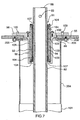
- Figure 5 is a sectional view of the mixing apparatus of Figure 2 along sight line 5-5 thereof;
- Figure 6 is an enlarged view of the encircled area "6" of Figure 5;
- Figure 7 is an enlarged view of the encircled area "7" of Figure 5;
- Figure 8A is an enlarged view of the encircled area "8A" of Figure 5 with an annular seal member deflated to permit linear reciprocation of the drive shaft;
- Figure 8B is a view similar to Figure 8A, showing the annular seal member inflated to seal against the drive shaft;
- Figure 9 is an enlarged perspective view from the top right of a portion of the preferred embodiment of mixing apparatus of Figures 1 through 8, with certain components removed for ease of illustration;
- Figure 10 is a partially exploded view of a portion of the apparatus of Figure 9;
- Figure 11A is a top plan view of the mixing head shown in Figures 1 - 4;
- Figure 11B is a side elevational view of the mixing head of Figure 11A;
- Figure 11C is a bottom plan view of the mixing head of Figure 11A;
- Figure 11D is a sectional view along sight line 11D-11D of Figure 11A;
- Figure 11E is a perspective view of the mixing head of Figure 11A;
- Figure 11F is a perspective view, on an enlarged scale, of the encircled area "11F" of Figure 11E;
- Figure 12A is a top plan view of a first alternate embodiment of the mixing head for use with the mixing apparatus shown in Figures 1-10;
- Figure 12B is a side elevational view of the mixing head of Figure 12A;
- Figure 12C is a bottom plan view of the mixing head of Figure 12A;
- Figure 12D is a sectional view along sight line 12D-12D of Figure 12A;
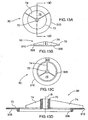
- Figure 13A is a top plan view of a second alternate embodiment of mixing head for use with the mixing apparatus shown in Figures 1-10;
- Figure 13B is a side elevational view of the mixing head of Figure 13D;
- Figure 13C is a bottom plan view of the mixing head of Figure 13A;
- Figure 13D is a sectional view along sight line 13D-13D of Figure 13A;
- Figure 14A is a top plan view of a third alternate embodiment for use with the mixing apparatus shown in Figures 1-10;
- Figure 14B is a side elevational view of the mixing head of Figure 14A;
- Figure 14C is a bottom plan view of the mixing head of Figure 14A;
- Figure 14D is a sectional view along sight line 14D-14D of Figure 14A.
- Figure 14E is a bottom perspective view of the mixing head of Figure 14A.
- a mixing apparatus according to a preferred embodiment of the present invention generally designated by the reference numeral 20.
- the mixing apparatus has particular utility when used in association with a vessel 21 having a contiguous sidewall 22 which is centered about and defines a longitudinal axis designated by the reference letter "A".
- the vessel 21 is a sewage digester, which does not form part of the invention, and which is generally cylindrical.
- the illustrated vessel 21 has a concave bottom wall 24 and a generally congruent convex shaped top wall 26.
- Municipal waste water digesters such as the vessel 21 are typically employed in municipal waste water treatment plants at a secondary, tertiary, or higher stage of treatment, such that the liquid waste 28 pumped into such a vessel 21 is relatively homogenous when it enters the vessel 21.
- the purpose of such digesters is to facilitate microbial or chemical breakdown (digestion) of the organic material contained in the liquid waste 28, which purpose is greatly facilitated by mixing or agitation of the liquid waste 28 within the interior 30 of the vessel 21.
- propeller type mixers (not shown) have been used for this purpose, but these have proven to be relatively inefficient in terms of their actual mixing efficiency (particularly in the regions adjacent to the sidewall 22 of the vessel 21), and in the power consumption required to achieve such mixing.
- a mixing apparatus 20 comprises a base plate 25, which base plate is removably mountable atop the vessel 21 by means of bolts or other fasteners (not shown) which extend through apertures 26 passing through the top plate 25, which top plate 25 is preferably strengthened in its center section by means of radially extending support ribs 29 (see Figure 5) extending thereunder.
- a sealing gasket (not shown) in interposed relation between the base plate 25 and the underlying top wall 26 of the vessel 21, but such gasket is not part of the present invention.
- the mixing apparatus 20 further comprises a table frame 50 removably mounted atop the base plate 25 by means of bolts 57 (see Figure 9) extending through foot flanges 53 positioned at the base of each of the table legs 52.
- a pair of tubular leg mount brackets 51 may also advantageously be mounted atop the base plate 25 to accept a respective pair of the table foot flanges 53 in supported relation thereon, thereby to spread the loading of the legs 52 more evenly over the surface of the base plate 25, and so as to minimize the need for piercing said base plate 24, thereby enhancing it's gas sealing integrity.
- the table frame 50 has a top plate 55 mounted at it's upper end above the four table legs 52, so as to provide a surface on which a housing 60 may be removably mounted, as described more fully below.
- the mixing apparatus 20 further comprises a mixing head generally designated by reference numeral 30, which mixing head itself comprises a generally annular blade body 32 for immersion for mixing into the liquid waste 28 to be mixed within the vessel 21, the blade body having a centrally positioned hub member 70 which defines a substantially vertically directed hub axis "B" (see, for example, Figures 5, 8 and 11D), which hub axis is substantially aligned, in use, with the longitudinal axis "A".
- the hub member 70 is attached to a ring portion 72 by means of a plurality of spokes 74 extending radially outwardly from the hub member 70, which spokes 74 are secured to the hub member 70 and the ring portion 72 by conventional fastening means, welding or the like.
- the ring portion 72 defines by its inner circumference an inner orifice 75, which orifice 75 has a centre of symmetry coincident in the embodiment shown in Figures 1 through 10 and in all of the remaining figures with the axis "B". Further details of the mixing head 30 are given below.
- a drive shaft designated by the general reference numeral 80, is provided in the form of a hollow tube for supporting the mixing head within the vessel 21, which drive shaft extends from a point of releasable connection with the hub member 70 upwardly into the housing 42 for releasable connection to the reciprocating drive assembly 40 substantially mounted therein in a manner more fully described below.
- the drive shaft 80 is itself comprised of two separate hollow tube sections, being an upper drive shaft section 82 and a lower drive shaft section 84, each being releasably interconnectable to the other in a manner more fully described below, or in any other operative manner.
- the drive shaft 80 need not be in two pieces; it could be a single piece; moreover, it could be in more than two pieces. However, greater utility in terms of ease of installation, servicing and disassembly flows from a multipart arrangement for the drive shaft 80, as will be appreciated to those skilled in the art after having read and considered this entire specification.
- the drive shaft 80 has a top end 86 disposed above the digester and extends therefrom, downwardly and substantially vertically, through an aperture 27 formed in the base plate 25 of the vessel 21 (see Figure 5) to a terminus 71 (see Figure 3A) bolted or otherwise removably connected to the hub member 70.
- the terminus 71 represents the point of releasable connection referenced in the previous paragraph.
- the drive shaft 80 includes an upper drive shaft section 82, which includes the top end 86 (see Figures 7 and 10), and a lower drive shaft section 84, which includes the terminus 71.
- the upper drive shaft section 82 is shown in detail in Figures 7, 8A and 10 and includes said top end 86 of the drive shaft 80, through which a dowel hole 83 is drilled, and a bottom end 85 which is threaded interiorly.
- a drive shaft mounting bracket 89 is tightly fit around the top end 86 of the drive shaft and has a complimentary reference hole (not numbered) positioned thereon for registry with the dowel hole 83.
- the dowel hole 83 is dimensioned to receive in frictionally retained relation a dowel pin 88 to prevent rotational movement of the top end 86 relative to the bracket 89.
- the drive shaft mounting bracket is shaped and otherwise dimensioned to mate with other components of the reciprocating drive assembly 40 to form a robust disconnectable assembly for imparting reciprocal longitudinal movement to the mixing head 30, as will be more fully described below.
- the upper drive shaft section 82 has a connector assembly 91 removably attached to its lower end 85 for releasable connection to the lower drive shaft section 84.
- the terminal connection assembly 91 comprises: a split ring taper lock 79; a coupler member 76A disposed adjacent the bottom end 85 of the upper drive shaft section 82 beneath the taper lock 78, and connected thereto by machine bolts (not shown); and an end plug 73 threadingly engaging the inside diameter of the bottom end 85 of the upper drive shaft section 82.
- This arrangement firmly secures the coupler member 76A to the bottom end 60 of the upper drive shaft section 82 in removable relation thereto.
- the coupler member 76A further presents, adjacent its lower extremity, a peripheral flange portion 76B, having mounting bores 77 circumferentially spaced therearound.
- the lower drive shaft section 84 has rigidly mounted at its upper end 63 a cap connector 87, said cap connector 87 having threaded bores 89 (see Figure 8A) which are in alignment with the mounting bores 77 of the terminal connection assembly 91.
- Bolts 95 pass through the bores of the peripheral flange position 76B to engage the complementary threaded bores 89, thereby to releasably connect the cap connector 87 (of the lower drive shaft section 84) to the connector assembly 91.
- the upper drive shaft section 82 and the lower drive shaft section 84 are releasably interconnectable one to the other.
- the table frame 50 has operably mounted thereon atop its top plate 55 a linear bearing assembly 90, as best seen in Figures 7 and 10, in proximal relation to the housing 42, with the upper section 82 of the drive shaft 80 operatively slidable therewithin.
- the linear bearing assembly 90 has its upper end 91 protruding above the top plate 55, and includes a bearing housing 94 through which the upper section 82 of the drive shaft 80 extends, and which linear bearing assembly 90 is adapted to guide the said section 82 for reciprocating motion; a mounting flange portion 96 surrounding the bearing housing 94 and secured upon the top plate 55 by bolts 100, and a boss portion 98 dimensioned to fit within an aperture 88 in the top plate 55 in close-fitting relation and also surrounding the bearing housing 94.
- the actual linear bearing material 92 that makes linear sliding contact with the upper section 82 preferably has a low co-efficient of friction and is of conventional construction and composition, and forms a cylindrical sleeve that is press-fit into the bearing housing 94.
- the mounting flange portion 96 and the boss portion 98 are formed integrally.
- An O-ring 102 is disposed about the boss portion 98, so as to arrest gas flow through the aperture 88 about the linear bearing assembly 90.
- Further annular seals 104 are provided within the bearing housing 94.
- the annular seals 104 are positioned in pairs, in back-to-back relation, at both ends of the bearing housing 94, so as to preserve grease within the bearing housing 94, and so as to arrest gas exchange between the interior of the vessel and the ambient atmosphere.
- Seals 103 are also provided between bearing housing 94 and the integrally-formed boss portion 98 and mounting flange portion 96 to arrest gas flow.
- seals 103 and 104 are mounted within the liner bearing assembly 90 in encircling gas sealing relation to the upper drive shaft section 82.
- a pair of seal retaining rings 107,107 are positioned one each at opposite ends of the bearing housing 94 to releasably hold the annular seals 104,104 in place around the upper drive shaft section 82.
- the bearing housing 94 is preferably of the self-aligning type, in that it includes a peripherally-extending arcuate ridge 105. This construction is advantageous, in that it permits the bearing housing 94 to shift slightly about ridge 105 in use, to accommodate off-centre loading of the reciprocating drive assembly 40, as may occur in use, and extends the life of the linear bearing material 92. Of course, when the bearing material 92 becomes worn, it may be removed and replaced, typically as a unit with the bearing housing 94.
- the mixer housing 42 is comprised of a generally rectangular cabinet removably mountable atop the top plate 55 of the table frame 50 in enclosing relation to the top end 86 of the drive shaft 80.
- the housing 42 preferably has a removable front cover plate 43, (which itself had a removable inspection plate 45, which plate can be easily opened for routine inspection and maintenance of the components of the reciprocating drive assembly 40 located therein). More involved maintenance will (including dismounting of the housing 42 from the table frame 50) require complete removal of the front cover plate 43, as described more fully below.
- the housing 42 also has an overextending housing base plate 118 adjacent its lower end, as shown in Figures 2, 4, 9, and 10.
- the base plate 118 is provided with elongate slots 120 external to the housing 42, through which slots bolts (not shown) pass into the top plate 55, thereby securably mounting the housing 42 atop the top plate 55 of the table frame 50 in removable contacting relation as aforesaid.
- the housing base plate 118 further comprises an open-ended notch 119 originating along a front edge 123 of the housing base plate 118, which notch 119 is shaped and dimensioned (as illustrated) to surroundingly receive the upper end 91 of the linear bearing assembly 90 within the arms 125,125 of the notch.
- the housing 42 is thereafter laterally slidable (as illustrated by arrow "L" in Figure 4) to effect removal of the upper end 91 of the linear bearing assembly 90 from within its starting orientation within the interior of the housing 42 (as seen in, for example, Figures 2 and 9) to a subsequent orientation where the linear bearing assembly 90 is exterior to the housing, as seen in Figure 4.
- This lateral movement allows quick and easy removal as a complete assembly of the components of the reciprocating drive mechanism 40 contained within the housing 42 from atop the table frame 50 for repair or replacement without having to disturb the drive shaft 80 subassembly mounted for reciprocating longitudinal sliding movement within the linear bearing assembly 90. This can considerably reduce down time of the vessel 21 and its associated costs and inconvenience.
- Such lateral sliding of the housing 42 can be greatly facilitated and a significant mechanical advantage can be achieved through the use of a screw jack assembly 38 operatively interconnected between the housing 42 and the top plate 55 of the table frame 50, as illustrated in Figures 3A and 3B.
- a screw jack assembly 38 includes a screw jack mount 162, a screw jack 164, and a jack nut 166.
- the screw jack mount 162 is mounted to the top plate 55 by bolts (not shown), and presents an upwardly-directed arcuate channel 168 in which is seated a waisted portion 170 of the jack nut 166.
- the screw jack 164 is threaded at one end into the jack nut 166 and has, at its opposite other end, a pair of anchoring bores 172 overlying a complimentary pair of threaded mounting sockets (not visible) formed in the housing base plate 118 to each accept a respective mounting bolt (not shown), thereby securing the opposite other end of the screw jack 164 to the housing 42. Tightening of the jack nut 166 causes the housing to be laterally pulled in the direction of arrow "L" of Figure 4.
- the screw jack assembly 38 is constructed out of mild steel. In environments wherein such assembly 38 might be prone to corrosion, it may readily be unbolted and stored in a noncorrosive environment when not in use.
- a drive motor 108 being, for example, an electric drive motor rated for between about 4 and 10 horsepower, is preferably mounted on the back of the housing 42 through the agency of a gear reduction unit 122, as seen in, for example, Figures 3A, 4, and 10.
- the gear reduction unit 122 has a conventional output shaft 127 which extends through a rear wall 124 of the housing 42 to drive the reciprocating drive assembly 40 mounted on the rear wall within the interior of the housing 42.
- the reciprocating drive assembly 40 is preferably a so-called "scotch yoke" mechanism, such that the reference numeral 40 will hereafter be used to denote the scotch yoke mechanism.
- the scotch yoke mechanism 40 described is structurally and functionally similar in operation to that described in published PCT application Number PCT/CA02/00528, although certain refinements and improvements thereover are incorporated into the preferred embodiment disclosed and claimed herein.
- the scotch yoke 40 illustrated includes a flywheel hub 126 adapted to receive in rotatable driven relation the output shaft 127 of the gear reduction unit 122, and a flywheel 128 rigidly attached to the flywheel hub 126 for rotation therewith about a rotational axis "R" (as seen in Figure 10) which axis extends substantially normal to the longitudinal axis "A".
- the flywheel 128 has formed therein three radially spaced bores 112a, a selected one of which is in retained receipt of a crank pin mounting sleeve 112b. Selection of a specific one of the bores will vary the stroke length of the mixing head 30, which stroke length is depicted by arrow "S" in Figure 1.
- Crank pin mounting sleeve 112b contains a centrally disposed socket for receiving in frictionally retained relation a crank pin 111a, which, when mounted in the socket, projects from the flywheel 128 in a direction substantially parallel to the rotational axis "R".
- the scotch yoke mechanism 40 further preferably includes, as illustrated, a wear plate block 138 having removable and replaceable upper 140a and lower 140b wear plates secured to its upper and lower surfaces, by counter-sunk screws (not shown), as best seen in Figure 10.
- the upper 140a and lower 140b wear plates are preferably constructed from graphite impregnated bronze, or other similar bearing-like material having a low co-efficient of friction and good wear life.
- the wear plate block 138 has a central bore 142 formed therethrough which bore is adapted to receive the crank pin 111a in rotatable relation by means of an intermediate roller bearing 111b.
- the crank pin 111a is retained by the inner race (not shown) of the roller bearing 111b.
- the roller bearing 111b is retained in the central bore 142 with the assistance of a spring C-clip 117 (see Figure 6).
- the crank pin mounting sleeve 112b, crank pin 111a, wear plate block 138, wear plates 140a, 140b, central bore 142 and intermediate roller bearing 111b combine together to form a crank member that projects from the flywheel 128 in a direction substantially parallel to the rotational axis "R".
- the scotch yoke assembly 40 further comprises a yoke slide 130, which is supported on the back wall 124 of the housing 42 for movement along a yoke axis "Y" (see Figure 6), which yoke axis is disposed substantially parallel to the longitudinal axis "A".
- the yoke slide 130 is releasably connected to the drive shaft 80 for imparting reciprocating longitudinal movement to the mixing heard 30 along the hub axis "B" during movement of the yoke slide 130 along the yoke axis "Y" as described more fully below.
- First and second guide assemblies each being a respective linear slide assembly 132, 134 are mounted on the rear wall 124 in laterally spaced relation to one another and in parallel relation to the yoke axis "Y" by means of counter-sunk machine screws 135.
- the guide assemblies each comprise a respective track slide 132',134', with each track slide having a pair of slide bogies 133,133 and 133',233' respectively retained on the track slides 132', 134' for operative sliding engagement along a pair of guide axes "GA1" and "GA2" (see Figure 6) extending substantially parallel to the yoke axis "Y".
- the slide bogies are each removably attached to the underside of the yoke slide by means of four machine screws 137 which pass through the body of the yoke slide 130 and into four correspondingly placed and threaded bores 137' formed on the upper surface of each of the slide bogies 133,133, 133',133' (see Figure 10).
- the yoke slide 130 is substantially disposed between the first 132 and second 134 guide assemblies for sliding engagement therewith along a pair of guide axes GA1, GA2 extending substantially parallel to the yoke axis "Y".
- a means for providing lubrication to each of the linear slide assemblies 132,134 is preferably provided as best seen in Figures 6 and 10.
- Such means comprises a grease nipple 175 positioned one each on an exposed longitudinal end of each one of the slide bogies 133,133,133',133', which nipple is in fluid communication with a grease channel (not shown) extending from the grease nipple 175 through the body of the respective slide bogie to a grease port positioned on the underside of each slide bogie 133,133,133',133' in overlying relation to its respective track slide 132',134'.
- the grease port is in fluid communication with the grease nipple 175 to selectively accept lubricating grease for distribution through said grease channel onto the respective one of the track slides 132',134' as said yoke slide 130 moves along the yoke axis "Y" as aforesaid.
- the yoke slide 130 has a substantially linear race 134 formed therein, with the opposed upper 134a and lower 134b surfaces thereof each being clad with a respective upper 139a and lower 139b bearing plate removably fastened thereto by means of countersunk machine screws, or the like (not shown).
- the upper 139a and lower 139b bearing plates are oriented with the planes defined by each oriented substantially normal to both the rotational axis "R" and to the yoke axis "Y”.
- both bearing plates 139a and 139b are preferably constructed from a frictionally wear-resistant material, such as hardened steel.
- the upper 139a bearing plate is preferably dimensioned to be slightly wider than the overlying upper 134a surface of the linear race 134 so as to form a protruding font ledge portion (best seen in Figure 9), whose purpose will become apparent below.
- the bore 142 of the wear plate block 138 operatively receives the crank member in rotatable driving relation, and the wear plate block 138 is mounted for constrained substantially horizontal sliding movement between the upper 140a and lower 140b wear plates, which wear plates are in turn in frictional sliding contact with a respective one of the upper 139a and lower 139b bearing plates.
- Such movement will in time cause wear of wear plates 140a, 140b, whereupon new wear plates may be substituted.
- a means for lubricating the surface of at least one of the upper 139a and lower 139b bearing plates (and consequently the upper 140a and lower 140b wear plates) is advantageously provided in order to prolong the service life of the scotch yoke assembly 40 and potentially lessen the time between bearing plate 139a, 139b or wear plate 140a, 140b maintenance and/or replacement.
- This means can be best seen and understood with reference to Figures 6 and 10, wherein it has been assigned the general reference numeral 180.
- This means for lubrication 180 comprises an oil storage reservoir 182 which is advantageously filled periodically as necessary with a relatively light machine oil (not shown), and which reservoir 182 is mounted, by means of a removable "C"-shaped bracket member 183, onto the yoke slide 130 at a position above the level of the upper bearing plate 139a so as to have the assistance of gravity in oil delivery to the bearing plate 139a.
- An oil flow control means in the form of a felt pad 184, is positioned between the oil reservoir and the operative contacting (i.e. lower) surface of the upper bearing plate 139a.
- the felt pad 184 sits in a fitted cavity formed for such purpose on the upper surface 186 of the upper bearing plate 139a, partially extending onto the projecting ledge portion thereof previously described.
- the reservoir 180 is in fluid communication with the oil flow control means 184 by way of a channel 187 formed in the "C"-shaped bracket member 183, which channel 187, when the yoke slide 13.0 is assembled as shown, is positioned in overlying relation to at least that portion of the felt pad 184 extending onto said projecting ledge.
- An oil delivery channel 187 extends from the bottom of the fitted cavity underlying the felt pad 184 through the body of the upper bearing plate 139a to connect with and terminate at an oil delivery port 189' positioned on the operative contacting surface 185 of the upper bearing plate 139a.
- the oil will travel therefrom (in a controlled manner influenced by gravity and the wicking effect of the felt) through the delivery channel 189 to exit in a slow dripping fashion from the delivery port 189' onto the surface of the upper bearing plate 139a.
- Spreading of the oil beyond the immediate area of the delivery port 189' across the operative contacting surface 185 (and, for that matter, across the upper wear plate 140a) will be assisted by the reciprocating sliding movement of the wear block 138 past the port 189' upon rotation of the flywheel 128 as described more fully below.
- Such reciprocating vertical motion of the yoke slide 130 is imparted to the upper section 82 of the drive shaft 80 by means of the drive shaft mounting bracket 89 fitted to the top end 86 of the drive shaft 80 (see Figure 10) which bracket 89 is rigidly attached to a shaft clamp bracket 146, as seen in Figure 9.
- the dowel pin 88 extending from the dowel hole 83 also extends into a complimentary dowel hole 69 in the clamp bracket 146, and the clamp bracket is bolted to the mounting bracket 89 in rigid, close-fitting relation by means of four mounting bolts 67 passing through the body of the clamp bracket 146 into the side flanges of the drive shaft mounting bracket 89, as best seen in Figure 10.
- the shaft clamp bracket 146 is, in turn, rigidly attached to the yoke slide 130 by means of four mounting bolts 60a, the rigidity of which attachment is assisted by insertion of a second dowel pin (not shown) in mating dowel sockets 61a and 61b formed in each of the clamp bracket 146 and the yoke slide 130.
- a draft tube 200 extends downwardly from a terminal flange 201 positioned above the base plate 25 to be immersed in the liquid waste 28, as seen in Figure 1.
- Such immersion tends to minimize the volume of gas that finds its way from the interior 31 of the vessel 21 up the draft tube through the aperture 27 in the base plate 25.
- a sealing means is still required for substantially preventing gasses formed in the vessel 21 above the level of the liquid waste 28 from leaking to atmosphere in undesirable quantities.
- gas sealing means preferably comprises a raised annular flange member 35 mounted atop the terminal flange 201 in encircling relation to the aperture 27 (see Figure 5) formed in the base plate 25.
- the raised annular flange member 35 includes an annular base ring 37 that is bolted to the top of the terminal flange 201 in surrounding relation to the aperture 27, as best seen in Figures 5 and 8A, with an intervening sealing gasket 202 interposed therebetween to seal against gas escape.
- the gas sealing means further comprises an upper annular flange member 204 mounted to the underside of the top plate 55 of the table frame 50 in encircling relation to the lower end of the linear bearing assembly 90 by bolts 206.
- a resilient gasket 206 is preferably interposed between the upper annular flange member 204 and the underside of the top plate 55 to facilitate gas-sealing mounting of the upper annular flange member 204 against the top plate 55.
- the gas sealing means further comprises, as discussed above the seals 104 positioned within the linear bearing assembly 90, and a sleeve member 161 (preferably in the form of a corrugated, bellows-style tube member) constructed from resilient rubber material.
- the sleeve member 161 has open ends which are resiliently mounted in gas-sealing removable relation, about each of the raised annular flange member 35 and the upper annular flange member 204, respectively.
- the gas sealing means of the preferred embodiment illustrated further comprises a secondary gas sealing means that can be invoked during maintenance of the mixing apparatus 21.
- this secondary gas sealing means comprises a substantially annular seal member 210 mounted on the interior of the annular flange member 35 for selective inflation (by, for example, air under pressure) through valved nozzle 211 to fill the void (212 in Figure 8A) between the lower drive shaft section and the interior wall 35' of the annular flange 35, when the sleeve member 161 is removed from the mixing apparatus 21 for servicing or maintenance.
- Figure 8A shows the sleeve member 161 in place, with the annular seal member 210 deflated, such as would be a normal usage configuration.
- Figure 8B shows the 161 removed, with annular seal member 210 inflated to seal against the upper drive shaft portion 84 so as to minimize gas leakage from the interior 31 of the vessel 21, such as would be a normal maintenance configuration.
- the foregoing provides a useful mixing apparatus 20 which provides for vertical reciprocating motion of the mixing head 30 a stroke distance designated by double headed arrow "S" in Figure 1, for admixture of the liquid contents 28 of the vessel 21.
- One advantage of the mixing apparatus 20 disclosed is its ease of maintenance, in that the upper drive shaft section 82 may, for maintenance or the like, be readily disconnected from the scotch yoke mechanism 40; the four mounting bolts 67 holding the clamp bracket 146 to the drive shaft mounting bracket 89 and the four mounting bolts 60a attaching the clamp bracket 146 to the yoke slide 130 need then merely be removed, whereupon the parts are mechanically disconnected, as shown in Figure 10. Following such disconnection, the bolts (not shown) securing the base plate 118 of the mixer housing 42 (by means of elongate slots 120) to the top plate 55 of the table frame 50 can be loosened, and the mixer housing 42, with the attached motor 108, gear reduction unit 122, reciprocating drive assembly 40, etc. can be slid along the top plate 55 of the table frame 50 in the direction of arrow "L" of Figure 4 by manipulation of the jack nut 166, as previously described.
- substantially annular seal member 210 will be first inflated through the valved nozzle 211 to prevent subsequent gas release from the vessel 21, and the lower drive shaft section 84 will be locked in place against longitudinal sliding prior to the aforementioned disconnection of the upper drive shaft section 82 (so as to avoid the drive shaft 50 and the attached mixing head 30 from dropping precipitously into the vessel 21).
- This locking function may conveniently be achieved by removing the flexible sleeve member 161 from its gas-sealed connection with the upper annular flange member 204 and with the raised annular flange member 35, and thereafter installing a lock means in the form of a releasable split-circle locking ring 36.
- the split-circle locking ring 36 has two semi-circular segments that can be tightened together for selectively gripping the outer circumference of the lower drive shaft section 84. Such tightening is accomplished by tightening four tangentially oriented bolts 33 (seen in section in Figure 8B), where it will be observed that the sleeve member 161 has been removed for servicing, and that the tightened split-circle locking ring is also in longitudinally blocking engagement with the annular flange member 35, thereby to prevent longitudinal sliding thereof relative to the annular flange 35.
- the locking ring 36 can be loosened (by loosening of the four tangentially oriented bolts 33), and thereafter removed from frictional engagement with the lower drive shaft portion 84.
- the sleeve member 161 can then be re-installed to its original gas sealed configuration.
- the substantially annular seal member 210 can be deflated through the valved nozzle 211, following which the mixing apparatus 20 may again be re-started.
- the jack nut 166 may simply be turned in the reverse direction, to urge the housing (in the opposite direction of arrow "L" of Figure 4) towards the top end 86 of the drive shaft member 50.
- each of the spokes 74 has an upper spine 74' which is covered with a convex shroud member 304.
- the shroud members 304 are attached to their respective spines 74' by screws, welding or the like. Their purpose is to minimize the tendency of debris prevalent in the liquid waste 28 found in municipal sewage digesters (such as, for example, rags and hair) from accumulating on the upper spines 74' of the spokes 74, which accumulation causes the motor 108 to draw more power to reciprocate the driving head 30, and may lead to more frequent servicing of the mixing apparatus 20.
- FIGS 12A through 12D illustrate a first alternate embodiment of mixing head 30 in accordance with the present invention which is generally similar to the embodiment of Figures 11A through 11F, with the following exceptions.
- no reinforcing annulus (or rib) 303 is provided and no convex shroud members 304a are provided.
- a convex lip member 305 is provided on the lower surface 306 of the ring portion 72 adjacent to the lower circumference 310 of the ring portion 72.
- This convex lip member 305 is substantially circular in cross-section, and is added to alter the micro-eddy currents around the outer circumference 310 of the mixing head 30, as it vertically reciprocates in the liquid 28 in the vessel 21, thereby changing the mixing properties in a manner that can be varied depending upon the physical characteristics of the lip member 305, and its proximity to the outer circumference 310.
- FIGS 13A through 13D illustrate a second alternate embodiment of mixing head 30 in accordance with the present invention, which embodiment is generally similar to the embodiment of Figures 12A through 12F, with the exception that a convex lip member 309 is provided on the lower surface 306 of the ring portion 72 adjacent to the orifice 75 in encircling relation to said orifice 75.
- This convex lip member 309 replaces the convex lip member 305 of the previous embodiment.
- the convex lip member 309 is substantially circular in cross-section, and is thought to alter the micro-eddy currents around the orifice 75 of the mixing head 30 as it vertically reciprocates in the liquid 28 in the vessel 21, thereby changing the mixing properties in a manner that can be varied in a controlled manner, depending upon the physical characteristics of the lip member 309 and its proximity to the orifice 75.
- Figures 14A through 14E illustrate a third alternate embodiment of mixing head 30 in accordance with the present invention.
- the ring portion 72 is not entirely flat across its extent, as in the embodiments of the other figures; rather, the ring portion 72 has a generally horizontal inner ring section 72a adjacent to the orifice 75 that is substantially flat across its extent, and an outer skirt section 72b that is contiguous with the inner ring section 72a, hut extends angularly upwardly from the inner ring section 72a, to define by its outer extent, the outside circumference of the ring portion 72.
- This arrangement causes more turbulence in the vicinity of the outer circumference 310 as ⁇ he mixing head 30 reciprocates.
Landscapes
- Chemical & Material Sciences (AREA)
- Chemical Kinetics & Catalysis (AREA)
- Mixers Of The Rotary Stirring Type (AREA)
- Thermally Insulated Containers For Foods (AREA)
- Accessories For Mixers (AREA)
Claims (38)
- Mischvorrichtung zur Verwendung mit einem Behälter (21) mit geschlossener Behälterwand (22), welche im Wesentlichen um eine Längsachse (A) zentriert ist und sie definiert, wobei die Mischvorrichtung (20) umfasst:eine Basisplatte (25), welche entfernbar an der Oberseite des Behälters (21) befestigbar ist;einen Tischrahmen (50), welcher entfernbar an der Oberseite der Basisplatte (25) befestigbar ist;ein Gehäuse (42), welches entfernbar an der Oberseite des Tischrahmens (50) befestigbar ist;einen Mischkopf (30), umfassend einen im Allgemeinen ringförmigen Schaufelkörper (32), zum Eintauchen in die Flüssigkeiten, welche im Behälter (21) gemischt werden sollen, wobei der Schaufelkörper (32) ein zentral positioniertes Nabenelement (70) aufweist, welches eine im Wesentlichen vertikal gerichtete Nabenachse (B) definiert, wobei das Nabenelement (70) an ein Kreisringelement (72) angebaut und von diesem umgeben ist, welches eine Öffnung (75) definiert, die ein Symmetriezentrum aufweist;eine Antriebswelle (80) als Träger des Mischkopfs (30) im Inneren des Behälters (21) und in einer Ausdehnung vom Nabenelement (70) bis zum Gehäuse (42);einen hin- und hergehenden Antriebsaufbau (40), welcher im Wesentlichen im Inneren des Gehäuses (42) angebracht ist, wobei der hin- und hergehenden Antriebsaufbau (40) operativ mit der Antriebswelle (80) verbindbar ist, um die Hin- und Herbewegung in Längsrichtung auf den Mischkopf (30) zu übertragen;eine Linearlagereinheit (90), welche am Tischrahmen (50) in nahem Bezug zum Gehäuse (42) befestigt ist, wobei die Antriebswelle (80) innerhalb der Linearlagereinheit (90) operativ verschiebbar ist;wobei die Mischvorrichtung (20) oben am Behälter (21) anbringbar ist, wobei sowohl die Antriebswelle (80), die Nabenachse (B) als auch das Symmetriezentrum im Wesentlichen mit der Längsachse (A) gefluchtet sind,dadurch gekennzeichnet, dass das Gehäuse (42) an seinem unteren Ende anliegend eine Gehäusebasisplatte (118) hat, dass der Tischrahmen (50) eine an seinem oberen Ende anliegende Deckplatte (55) hat und dass das Gehäuse (42) an der Oberseite der Deckplatte (55) entfernbar aufliegend befestigbar ist.
- Mischvorrichtung (20) nach Anspruch 1, wobei das Gehäuse (42) eine entfernbare vordere Abdeckplatte (43) aufweist, die Linearlagereinheit (90) betriebsfähig an der Deckplatte (55) befestigbar ist, wobei das obere Ende darüber in das Innere des Gehäuses (42) vorspringt und wobei das Gehäuse (42) lateral verschiebbar ist, um das obere Ende aus dem Inneren des Gehäuses (42) hinauszubewegen, wenn die vordere Abdeckplatte (43) des Gehäuses (42) entfernt ist und die Antriebswelle (80) operational vom hin- und hergehenden Antriebsaufbau (40) gelöst ist, mittels eines einseitig offenen Kerbeinschnitts (119) an einer Vorderkante der Gehäusebasisplatte (118), wobei der einseitig offene Einschnitt (119) so ausgebildet und dimensioniert ist, um das obere Ende innerhalb der Schenkel des Einschnitts (119) umfassend aufzunehmen.
- Mischvorrichtung (20) nach Anspruch 2, weiter umfassend eine Schraubenwindeneinheit (38), die zur mechanischen Unterstützung beim lateralen Verschieben des Gehäuses (42) koppelnd wirksam zwischen dem Gehäuse (42) und dem Tischrahmen (50) angeordnet ist.
- Mischvorrichtung (20) nach Anspruch 1, wobei der Tischrahmen (50) eine Mehrzahl von Tischbeinen (52) aufweist und wobei der Tischrahmen (50) an der Oberseite der Basisplatte (25) mittels der Tischbeine (52) entfernbar befestigbar ist.
- Mischvorrichtung (20) nach Anspruch 4, wobei die Antriebswelle (80) wenigstens zwei Abschnitte (82,84) umfasst, die miteinander lösbar verbindbar sind, wobei sie einen oberen Antriebswellenabschnitt (82) und einen untere Antriebswellenabschnitt (84) darstellen.
- Mischvorrichtung (20) nach Anspruch 5, wobei der obere Antriebswellenabschnitt (82) so dimensioniert und im Übrigen so angepasst ist, um sich von der operativen Verbindung mit dem hin- und hergehenden Antriebsaufbau (40) durch die Linearlagereinheit bis zu einem Punkt lösbarer Verbindung mit dem unteren Antriebswellenabschnitt (84) zu erstrecken, wobei sich dieser Punkt zu jedem Zeitpunkt des Betriebes der Mischvorrichtung (20) oberhalb der Basisplatte (25) befindet.
- Mischvorrichtung (20) nach Anspruch 6, wobei sich der untere Antriebswellenabschnitt (84) von dem Punkt der lösbaren Verbindung mit dem oberen Antriebswellenabschnitt (82) durch eine Öffnung (27) in der Basisplatte (25) erstreckt, um an einem Verbindungspunkt (71) mit dem Nabenelement (70) zu enden.
- Mischvorrichtung (20) nach Anspruch 7, wobei ein erhöhtes ringförmiges Flanschelement (35) an der Basisplatte (25) angebracht ist, wobei es das Loch (27) kreisförmig umgibt, und wobei ein Sperrelement zur Verfügung steht, um wahlweise mit dem unteren Antriebswellenabschnitt (84) und dem ringförmigen Flanschteil (35) zusammenzuwirken, um eine Gleitbewegung des unteren Antriebswellenabschnittes (84) in Längsrichtung relativ zum ringförmigen Flanschteil (35) zu verhindern.
- Mischvorrichtung (20) nach Anspruch 8, wobei das Sperrelement einen lösbaren, geteilten Verschlussring (36) umfasst.
- Mischvorrichtung (20) nach Anspruch 1, wobei der Behälter (21) dem Mischen von Flüssigkeiten dient und ein abgedichteter Behälter (21) mit einer Deckenwand (26) ist; wobei die Basisplatte (25) an der Deckenwand (26) in abgedichteter Verbindung damit entfernbar befestigbar ist; wobei sich die Antriebswelle (80) durch ein Loch (27) in der Basisplatte (25) erstreckt und in das Gehäuse (42) reicht; und wobei die Mischvorrichtung (20) außerdem ein Abdichtungsmittel umfasst, das im Wesentlichen verhindert, dass Gase, die sich im Behälter (21) über der Flüssigkeit gebildet haben, durch das Loch (27) in der Basisplatte (25) in die Atmosphäre entweichen.
- Mischvorrichtung (20) nach Anspruch 10, wobei das Gehäuse (42) eine entfernbare vordere Abdeckplatte (43) hat, die Linearlagereinheit (90) betriebsfähig an der Deckplatte (55) befestigbar ist, wobei das obere Ende darüber in das Innere des Gehäuses (42) vorspringt und das untere Ende unter die Deckplatte (55) vorspringt und wobei das Gehäuse (42) lateral verschiebbar ist, um das obere Ende aus dem Inneren des Gehäuses (42) zu entfernen, wenn die vordere Abdeckplatte (43) des Gehäuses (42) entfernt ist und die Antriebswelle (80) betrieblich vom hin- und hergehenden Antriebsaufbau (40) mittels eines einseitig offenen Einschnitts (119) an einer Vorderkante der Gehäusebasisplatte (118) gelöst ist, wobei der einseitig offene Einschnitt (119) so ausgebildet und dimensioniert ist, um das obere Ende in den Schenkeln des Einschnitts (119) umfassend aufzunehmen.
- Mischvorrichtung (20) nach Anspruch 11, weiter umfassend eine Schraubenwindeneinheit (38), die zur mechanischen Unterstützung beim lateralen Verschieben des Gehäuses (42) koppelnd wirksam zwischen dem Gehäuse (42) und dem Tischrahmen (50) angeordnet ist.
- Mischvorrichtung (20) nach Anspruch 11, wobei der Tischrahmen (50) mehrere Tischbeine (52) hat, und der Tischrahmen (50) an der Oberseite der Basisplatte (25) mittels der Tischbeine (52) entfernbar befestigbar ist.
- Mischvorrichtung (20) nach Anspruch 13, wobei die Antriebswelle (80) wenigstens zwei Abschnitte (82,84) umfasst, die als ein oberer Antriebswellenabschnitt (82) und ein unterer Antriebswellenabschnitt (84) miteinander lösbar verbindbar sind.
- Mischvorrichtung (20) nach Anspruch 14, wobei der obere Antriebswellenabschnitt (82) so dimensioniert und im Übrigen so angepasst ist, um sich von der operativen Verbindung mit dem hin- und hergehenden Antriebsaufbau (40) durch die Linearlagereinheit bis zu einem Punkt lösbarer Verbindung mit dem unteren Antriebswellenabschnitt (84) zu erstrecken, wobei sich dieser Punkt zu jedem Zeitpunkt des Betriebes der Mischvorrichtung (20) oberhalb der Basisplatte (25) befindet.
- Mischvorrichtung (20) nach Anspruch 15, wobei der untere Antriebswellenabschnitt (84) von dem Punkt der lösbaren Verbindung mit dem oberen Antriebswellenabschnitt (82) durch ein Loch (27) in der Basisplatte (25) erstreckt, um an einem Verbindungspunkt (71) mit dem Nabenelement (70) zu enden.
- Mischvorrichtung (20) nach Anspruch 16, wobei das Abdichtungsmittel umfasst: ein unteres ringförmiges Flanschelement (35), welches oben auf der Basisplatte (25) in gasdichter Beziehung damit und die Öffnung (27) kreisförmig umgebend angebracht ist, ein oberes ringförmiges Flanschelement (204), das auf der Unterseite der Deckplatte (50) in gasdichter Beziehung zur Deckplatte (50) und das untere Ende der Linearlagereinheit (90) kreisförmig umgebend angebracht ist, eines oder mehrere elastische Abdichtungsmitteln, die in der Linearlagereinheit (90) in umgebender, gasdichter Beziehung mit dem oberen Antriebswellenabschnitt (82) angebracht sind, und ein Buchsenelement (161), das sich vom unteren ringförmigen Flanschelement (35) zum oberen ringförmigen Flanschelement (204) erstreckt, wobei das Buchsenelement (161) mit den beiden ringförmigen Flanschelementen in gasdichter, umfassender Beziehung mit diesen lösbar verbindbar ist.
- Mischvorrichtung (20) nach Anspruch 16, wobei das Buchsenelement (161) ein gewelltes, faltenbalgartiges, biegsames Schlauchelement ist, welches aus elastischem Gummimaterial hergestellt ist.
- Mischvorrichtung (20) nach Anspruch 18, wobei das Abdichtungsmittel außerdem ein im Wesentlichen ringförmiges Dichtungselement (210) umfasst, das an der Innenseite des ringförmigen Flanschelementes (35) zum wahlweisen Aufblasen angebracht ist, um den Leerraum zwischen dem unteren Antriebswellenabschnitt (84) und dem Inneren des Flansches (35) zu füllen, wenn das Buchsenelement (161) von der Mischvorrichtung (20) zu Servicezwecken derselben abgenommen wird.
- Mischvorrichtung (20) nach Anspruch 1, wobei der hin- und hergehende Antriebsaufbau (40) umfasst:eine Kreuzschubkurbel mit:einem Schwungrad (128), das zur Rotation um eine Rotationsachse (R) befestigt ist, welche sich im Wesentlichen normal zur Längsachse (A) erstreckt;einem Kurbelelement, das von dem Schwungrad (128) vorragt in einer Richtung, welche im Wesentlichen zur Rotationsachse (R) parallel ist;einem Kreuzschlitten (130), der vom Gehäuse (42) zur Bewegung entlang einer Jochachse (Y) getragen wird, welche im Wesentlichen parallel zur Längsachse (A) liegt, wobei der Kreuzschlitten (130) lösbar mit der Welle (80) verbunden ist, wobei der Kreuzschlitten eine im Wesentlichen lineare Laufbahn (134) mit einander gegenüberliegender oberer und unterer Fläche (134a, 134b), welche darin zum operativen Kontakt mit dem Kurbelteil eingebaut sind, aufweist, wobei die Laufbahn (134) innerhalb des Kreuzschlittens (130) so angeordnet ist, dass die obere und die untere der einander gegenüberliegenden Flächen jeweils im Wesentlichen normal zu sowohl der Rotationsachse (R) als auch der Jochachse (Y) ausgerichtet sind;einer erster und zweiter Führungseinheit (132, 134) in operativer Verbindung mit dem Gehäuse (42) und mit dem Kreuzschlitten (130), um mit diesem in gleitendem Eingriff entlang zweier Führungsachsen (GA1, GA2) zu stehen, welche sich im Wesentlichen parallel zur Jochachse (Y) erstrecken, wobei die erste und die zweite Führungseinheit (132, 134) seitlich zu einander beabstandet sind, wobei der Kreuzschlitten (130) im Wesentlichen dazwischen angeordnet ist;wobei bei rotierendem Antrieb des Schwungrades (128) das Kurbelelement veranlasst wird, sich innerhalb der Laufbahn (134) linear zu verschieben und so den Kreuzschlitten (130) zu veranlassen, den Führungseinheiten (132, 134) gleitend zu folgen und sich so entlang der Jochachse (Y) zu bewegen, um so Hin- und Herbewegung der Welle (80) und des Mischkopfs (30) in Längsrichtung zu bewirken.
- Mischvorrichtung (20) nach Anspruch 20, wobei die erste und die zweite Führungseinheit (132, 134) je eine lineare Gleiteinheit bilden.
- Mischvorrichtung (20) nach Anspruch 20, wobei beide obere als auch untere gegenüberliegende Flächen (134a, 134b), der linearen Laufbahn (134) jeweils mit einer Gleitplatte (139a, 139b) belegt sind, die entfernbar daran befestigt ist.
- Mischvorrichtung (20) nach Anspruch 22, wobei die Kreuzkurbel außerdem einen Verschleißplattenblock (138) mit entfernbaren Verschleißplatten oben und unten (140a, 140b) umfasst, wobei dieser Verschleißplattenblock (138) eine Bohrung (142) aufweist, welche darin ausgebildet ist, um das Kurbelelement (111) operativ als rotierenden Antrieb aufzunehmen, wobei der Verschleißplattenblock (138) für die geführte Gleitbewegung zwischen der oberen und der unteren der gegenüberliegenden Flächen einsetzbar ist, wobei die oberen und die unteren Verschleißplatten (140a, 140b) je mit jeweils einer der oberen und der unteren Gleitplatten (139a, 139b) in reibendem Gleitkontakt stehen.
- Mischvorrichtung (20) nach Anspruch 23, wobei ein Mittel zur Schmierung für die Oberfläche von wenigstens einer der oberen und unteren Gleitplatten (139a, 139b) vorgesehen ist.
- Mischvorrichtung (20) nach Anspruch 24, wobei das Mittel zur Schmierung einen Öltank (182), der am Kreuzschlitten (130) befestigt ist, in einer Position über dem Niveau wenigstens einer der oberen und unteren Gleitplatten (139a, 139b), wobei dieser Tank (182) in Fließverbindung mit einem Mittel zur Steuerung des Ölflusses (184) steht, das zwischen dem Öltank und einer operativen Kontaktfläche wenigstens einer der oberen und unteren Gleitplatten (139a, 139b) angeordnet ist; und einen Ölspeisekanal oder mehrere Ölspeisekanäle (187) umfasst, welche sich von dem Mittel zur Steuerung des Ölflusses (184) zu einer oder zu mehreren Ölaustrittsstellen (189'), die auf der operativen Kontaktfläche angeordnet sind, zur Abgabe von Öl, das sich im Öltank (182) befindet, an wenigstens einer der oberen und unteren Gleitplatten (139a, 139b) erstrecken.
- Mischvorrichtung (20) nach Anspruch 25, wobei ein oder mehrere Ölspeisekanäle (187) und eine oder mehrere Ölaustrittsstellen (189') in jeder der oberen und unteren Gleitplatten (139a, 139b) zur Verfügung stehen, wobei zwei Öltanks (182), wie zuvor ausgeführt, am Kreuzschlitten (130) zur Verfügung stehen, wobei jedes Reservoir (182) in Fließverbindung mit je einem Steuerungsmittel des Ölflusses (184) steht, welches zwischen dem Tank (182) und der jeweiligen operativen Kontaktfläche wenigstens einer der oberen und unteren Gleitplatten (139a, 139b) angeordnet ist, so dass Öl, das sich im jeweiligen Öltank (182) befindet, jeweils zu einer der oberen und unteren Gleitplatten (139a, 139b) gelangt.
- Mischvorrichtung (20) nach Anspruch 26, wobei das Steuerungsmittel für den Ölfluss ein Filzkissen (184) ist, das sich über den Eingangsbereich zu dem Ölkanal oder zu den Ölkanälen (187) erstreckt.
- Mischvorrichtung (20) nach Anspruch 21, wobei ein Mittel zur Bereitstellung der Schmierung für jede der beiden linearen Gleiteinheiten (132, 134) der ersten und zweiten Führungseinheit zur Verfügung steht.
- Mischvorrichtung (20) nach Anspruch 28, wobei die linearen Gleiteinheiten (132, 134) je eine Gleitschiene (132', 134') umfassen, mit einem Gleitgestell oder mehreren Gleitgestellen (133, 133'), wobei das Gleitgestell oder die Gleitgestelle (133, 133') auf der Gleitschiene (132', 134') für das operatives Zusammenwirken im Gleitvorgang entlang je einer der Führungsachsen (GA1, GA2), die von der Gleitschiene definiert ist (132', 134'), festgehalten sind und wobei das Mittel zur Bereitstellung der Schmierung für jede der beiden linearen Gleiteinheiten (132, 134) einen Schmiermittelkanal umfasst, der von einer Schmierstelle ausgeht, die an jedem Gleitgestell (133, 133') angebracht ist, das auf seiner jeweiligen Gleitschiene (132', 134') aufliegend angeordnet ist, wobei diese Schmierstelle in Fließverbindung steht mit einem Schmiernippel (175), der am Gleitgestell (133, 133') angeordnet und so ausgelegt ist, wahlweise Schmierfett zur Verteilung durch den Schmiermittelkanal auf die jeweilige Gleitschiene (132', 134') aufzunehmen, wenn der Kreuzschlitten (130) sich entlang der Jochachse (Y), wie zuvor ausgeführt, bewegt.
- Mischvorrichtung (20) nach Anspruch 1, wobei das Nabenelement (70) an das Kreisringelement (72) so angebaut ist, dass es auf der Öffnung (75) und auf dem Kreisringelement (72) mittels einer Mehrzahl von Speichen (74) sitzt, welche sich vom Nabenelement (70) radial nach außen erstrecken.
- Mischvorrichtung (20) nach Anspruch 30, wobei jedes der Speichenelemente (74) einen oberen Gratrücken (74') mit einem konvexes Mantelteil (304), welcher daran in nach unten abfallender, aufliegender Lage angefügt ist, aufweist.
- Mischvorrichtung (20) nach Anspruch 1, wobei ein verstärkender Ring (303) benachbart dem äußeren Umfang (310) des Kreisringabschnittes (72) vorgesehen ist.
- Mischvorrichtung (20) nach Anspruch 30, wobei ein verstärkender Ring benachbart dem unteren äußeren Umfang des Kreisringabschnittes (72) vorgesehen ist.
- Mischvorrichtung (20) nach Anspruch 1, wobei ein konvexes Lippenelement (309) auf dem Kreisringabschnitt (72) benachbart der Öffnung (75) angeordnet ist und sie kreisförmig umgibt.
- Mischvorrichtung (20) nach Anspruch 30, wobei ein konvexes Lippenelement (309) auf einer unteren Fläche (306) des Kreisringabschnittes (72) benachbart der Öffnung (75) angeordnet ist und sie kreisförmig umgibt.
- Mischvorrichtung (20) nach Anspruch 1, wobei ein konvexes Lippenelement (309) am Kreisringabschnitt (72) benachbart dem äußeren Umfang des Kreisringabschnittes (72) angeordnet ist.
- Mischvorrichtung (20) nach Anspruch 30, wobei ein konvexes Lippenelement (309) an einer unteren Fläche des Kreisringabschnittes (72) benachbart dem äußeren Umfang des Kreisringabschnittes (72) angeordnet ist.
- Mischvorrichtung (20) nach Anspruch 30, wobei der Kreisringabschnitt (72) einen im Allgemeinen horizontalen inneren Ringabschnitt (72a), der die Öffnung (75) umgibt und sie definiert, und einen äußeren Schürzenabschnitt (72b) umfasst, welcher mit dem inneren Ringabschnitt (72a) zusammenhängt und sich in einem Winkel nach oben vom inneren Ringabschnitt (72a) erstreckt, um seine äußeren Ausmaße den Außenumfang des Ringabschnittes (72) zu definieren.
Priority Applications (1)
| Application Number | Priority Date | Filing Date | Title |
|---|---|---|---|
| PL04731867T PL1624955T3 (pl) | 2003-05-09 | 2004-05-10 | System mieszania cieczy dla naczyń zamkniętych |
Applications Claiming Priority (2)
| Application Number | Priority Date | Filing Date | Title |
|---|---|---|---|
| US46902603P | 2003-05-09 | 2003-05-09 | |
| PCT/CA2004/000704 WO2004098762A1 (en) | 2003-05-09 | 2004-05-10 | Liquid mixing system for closed vessels |
Publications (2)
| Publication Number | Publication Date |
|---|---|
| EP1624955A1 EP1624955A1 (de) | 2006-02-15 |
| EP1624955B1 true EP1624955B1 (de) | 2007-02-07 |
Family
ID=33435215
Family Applications (1)
| Application Number | Title | Priority Date | Filing Date |
|---|---|---|---|
| EP04731867A Expired - Lifetime EP1624955B1 (de) | 2003-05-09 | 2004-05-10 | Flüssigkeitmischvorrichtung für geschlossene behälter |
Country Status (10)
| Country | Link |
|---|---|
| US (1) | US7399112B2 (de) |
| EP (1) | EP1624955B1 (de) |
| AT (1) | ATE353246T1 (de) |
| CA (1) | CA2547716C (de) |
| DE (1) | DE602004004649T2 (de) |
| DK (1) | DK1624955T3 (de) |
| ES (1) | ES2281800T3 (de) |
| PL (1) | PL1624955T3 (de) |
| PT (1) | PT1624955E (de) |
| WO (1) | WO2004098762A1 (de) |
Families Citing this family (17)
| Publication number | Priority date | Publication date | Assignee | Title |
|---|---|---|---|---|
| US20060070812A1 (en) * | 2004-09-24 | 2006-04-06 | Eggleton Jerry W | Battery-operated grease gun |
| US7685896B2 (en) * | 2005-05-05 | 2010-03-30 | Enersave Fluid Mixers Inc. | Fluid mixing apparatus |
| WO2009042725A1 (en) * | 2007-09-24 | 2009-04-02 | Olympus Technologies Inc. | Systems and methods for ballasting covers for gas-holding sludge digestors |
| US8978419B2 (en) * | 2009-11-30 | 2015-03-17 | Corning Incorporated | Devices for controlling atmosphere over molten-glass free-surfaces |
| US8522545B2 (en) * | 2010-06-22 | 2013-09-03 | Neil Tice | Thermal engine capable of utilizing low-temperature sources of heat |
| US10233788B1 (en) | 2012-04-10 | 2019-03-19 | Neil Tice | Method and apparatus utilizing thermally conductive pumps for conversion of thermal energy to mechanical energy |
| CA2865978C (en) * | 2013-04-19 | 2015-09-01 | Gary Haughton | Linear motion mixer |
| AT515084B1 (de) | 2014-01-27 | 2015-06-15 | Fleck Vinzenz Dipl Ing | Vorrichtung und Verfahren zum Durchmischen einer Masse |
| US9101893B1 (en) * | 2014-03-17 | 2015-08-11 | Advanced Scientifics, Inc. | Mixing assembly and mixing method |
| US20170253512A1 (en) * | 2016-03-04 | 2017-09-07 | Ovivo Inc. | Municipal Mixing with Reciprocating Motion Disk |
| DE102016112312B4 (de) | 2016-07-05 | 2018-09-27 | Stefan Kuhn | Sicherheitseinrichtung für ein Rührwerk |
| WO2018102916A1 (en) * | 2016-12-05 | 2018-06-14 | Enersave Fluid Mixers Inc. | Fluidically powered linear motion mixer |
| US10443694B2 (en) | 2018-02-01 | 2019-10-15 | Envirodyne Systems Inc. | Apparatus for converting rotation motion to linear reciprocating motion |
| CN112871037A (zh) * | 2021-01-28 | 2021-06-01 | 颜廷梅 | 临床药学药剂调制装置 |
| US12151220B2 (en) | 2021-03-19 | 2024-11-26 | Ovivo Inc. | Vertical motion mixing drive |
| CN114405356B (zh) * | 2022-01-21 | 2023-03-24 | 广西壮族自治区农业科学院 | 一种培养土制备搅拌设备及其输送装置 |
| CN115228353B (zh) * | 2022-07-20 | 2024-07-26 | 江苏神华药业有限公司 | 一种制备口服液的原料混配送料机构 |
Family Cites Families (39)
| Publication number | Priority date | Publication date | Assignee | Title |
|---|---|---|---|---|
| US567503A (en) * | 1896-09-08 | pelatan | ||
| DE7416500U (de) | 1974-08-22 | Messerschmitt Boelkow Blohm Gmbh | Einrichtung zum Herstellen von Emulsionen unter dem Einfluß mechanischer Schwingungen | |
| US52890A (en) * | 1866-02-27 | Improvement in churns | ||
| US1345312A (en) * | 1919-08-18 | 1920-06-29 | William F Blake | Clothes-washing machine |
| US1408596A (en) * | 1921-04-11 | 1922-03-07 | Heinrich Erich | Clothes-washing machine |
| US2064402A (en) * | 1933-10-19 | 1936-12-15 | British Emulsifiers Ltd | Emulsification of butter and milk for the production of artificial cream |
| DE970926C (de) * | 1948-02-05 | 1958-11-13 | Mueller Hans | Vorrichtung zum Mischen, Ruehren usw. von Fluessigkeiten |
| US2557503A (en) * | 1949-04-06 | 1951-06-19 | Jr George B Hogaboom | Anode for electroplating phonograph recordings and shells produced therefrom |
| US2661938A (en) * | 1950-06-30 | 1953-12-08 | Standard Oil Co | Electromagnetic stirrer for highpressure contactors |
| US3214148A (en) * | 1963-12-18 | 1965-10-26 | J C Thomas | Agitator |
| GB1147378A (en) | 1966-12-19 | 1969-04-02 | Christopher John Davis | Apparatus for producing varied illumination effects |
| US3560366A (en) * | 1968-04-12 | 1971-02-02 | Oscar Fisher | Ag-o-mat silver recovery unit |
| FR1604693A (en) | 1968-12-31 | 1972-01-03 | Vat for the culture of the aphthous virus - and for biological substances | |
| US3912237A (en) * | 1969-06-26 | 1975-10-14 | Ostberg Jan Erik | Method and apparatus for moving of liquid phases in industrial processes |
| DE7504145U (de) | 1974-02-12 | 1975-06-19 | Mueller H | Vorrichtung zum Schwingmischen in Flüssigkeiten |
| US4169681A (en) * | 1974-11-06 | 1979-10-02 | Nihon Senshoku Kikai Kabushiki Kaisha | Liquid stirring apparatus |
| US4302318A (en) * | 1976-04-05 | 1981-11-24 | Mock Karl J | Means for recovering silver from photo chemicals |
| US4054503A (en) * | 1976-10-14 | 1977-10-18 | Ag-Met, Inc. | Portable metal recovery apparatus |
| US4125439A (en) * | 1977-05-31 | 1978-11-14 | National Research Development Corporation | Electrochemical cells and methods of electrolysis |
| US4189362A (en) * | 1979-01-15 | 1980-02-19 | Olin Corporation | Method of purifying aqueous solutions of alkali metal hydroxides |
| SU967541A1 (ru) | 1979-06-15 | 1982-10-23 | Предприятие П/Я Р-6956 | Реакционный аппарат с виброперемешиванием |
| SU858898A1 (ru) | 1979-12-17 | 1981-08-30 | Предприятие П/Я Р-6956 | Вибрационный смеситель |
| US4319971A (en) * | 1981-03-26 | 1982-03-16 | Metal Extraction Processes Corporation | Method and means for recovering silver by electrolysis |
| US4534914A (en) * | 1981-12-23 | 1985-08-13 | Nihon Sanso Kabushiki Kaisha | Method and apparatus for producing vortex rings of a gas in a liquid |
| US4440616A (en) * | 1982-09-30 | 1984-04-03 | General Dental Inc. | Metal collector |
| US4439300A (en) * | 1983-04-01 | 1984-03-27 | General Dental, Inc. | Vortex type metal collector |
| FR2605244A1 (fr) | 1986-10-20 | 1988-04-22 | Bionaz Ets | Procede d'agitation d'un fluide par un mouvement de va-et-vient vertical et agitateur correspondant |
| JPS63104638A (ja) | 1986-10-20 | 1988-05-10 | Tsukuba Eng:Kk | 液体撹拌装置 |
| US5100242A (en) * | 1987-03-20 | 1992-03-31 | Brian Latto | Vortex ring mixers |
| US5052813A (en) * | 1988-11-08 | 1991-10-01 | Brian Latto | Tube type vortex ring mixers |
| US5813760A (en) * | 1996-10-24 | 1998-09-29 | Binks Manufacturing Company | Reciprocating mix tank agitator and process for mixing the liquid contents of the tank |
| US5738018A (en) | 1997-01-23 | 1998-04-14 | Midwest Tropical, Inc. | Table with rising bubble display |
| US5947784A (en) * | 1997-03-11 | 1999-09-07 | Cullen; James R. | Apparatus for producing toroidal bubbles and method |
| US6007237A (en) * | 1997-05-29 | 1999-12-28 | Latto; Brian | Vortex ring mixer controlled mixing device |
| JPH11184420A (ja) | 1997-12-18 | 1999-07-09 | Mitsubishi Electric Corp | 渦輪発生装置、それを用いた表示装置及び表示方法 |
| US6070348A (en) * | 1998-11-04 | 2000-06-06 | Bianchetti; Paul E. | Bubble display device |
| DE60227358D1 (de) | 2001-04-17 | 2008-08-14 | Enersave Fluid Mixers Inc | Flüssigkeitsmischvorrichtung |
| US6830369B2 (en) * | 2002-04-17 | 2004-12-14 | Enersave Fluid Mixers Inc. | Mixing apparatus |
| US7364351B2 (en) * | 2002-11-15 | 2008-04-29 | Enersave Fluid Mixers Inc. | Fluid mixing apparatus |
-
2004
- 2004-05-10 EP EP04731867A patent/EP1624955B1/de not_active Expired - Lifetime
- 2004-05-10 AT AT04731867T patent/ATE353246T1/de active
- 2004-05-10 PT PT04731867T patent/PT1624955E/pt unknown
- 2004-05-10 US US10/556,320 patent/US7399112B2/en not_active Expired - Lifetime
- 2004-05-10 WO PCT/CA2004/000704 patent/WO2004098762A1/en not_active Ceased
- 2004-05-10 ES ES04731867T patent/ES2281800T3/es not_active Expired - Lifetime
- 2004-05-10 PL PL04731867T patent/PL1624955T3/pl unknown
- 2004-05-10 DK DK04731867T patent/DK1624955T3/da active
- 2004-05-10 CA CA002547716A patent/CA2547716C/en not_active Expired - Lifetime
- 2004-05-10 DE DE602004004649T patent/DE602004004649T2/de not_active Expired - Lifetime
Also Published As
| Publication number | Publication date |
|---|---|
| ATE353246T1 (de) | 2007-02-15 |
| DE602004004649T2 (de) | 2007-11-08 |
| DE602004004649D1 (de) | 2007-03-22 |
| WO2004098762A1 (en) | 2004-11-18 |
| PL1624955T3 (pl) | 2007-07-31 |
| US20060221766A1 (en) | 2006-10-05 |
| CA2547716A1 (en) | 2004-11-18 |
| PT1624955E (pt) | 2007-05-31 |
| EP1624955A1 (de) | 2006-02-15 |
| ES2281800T3 (es) | 2007-10-01 |
| US7399112B2 (en) | 2008-07-15 |
| CA2547716C (en) | 2007-02-20 |
| DK1624955T3 (da) | 2007-06-04 |
Similar Documents
| Publication | Publication Date | Title |
|---|---|---|
| EP1624955B1 (de) | Flüssigkeitmischvorrichtung für geschlossene behälter | |
| US4422771A (en) | Downflow mixer | |
| US3910728A (en) | Dewatering pump apparatus | |
| US5762833A (en) | Aerator with a removable stator and method of repairing the same | |
| DE102009056967B4 (de) | Mischvorrichtung | |
| GB2052278A (en) | Fluid flow apparatus | |
| EP0147108A2 (de) | Vorrichtung und Verfahren für die Behandlung von Abwasserschlamm | |
| CN211111226U (zh) | 一种用于污水处理的絮凝装置 | |
| CN218890526U (zh) | 一种高压搅拌反应釜 | |
| CN219232355U (zh) | 一种乳化油生产用反应釜 | |
| CN213610776U (zh) | 一种电镀生产线高效溶液搅拌装置 | |
| CN2285157Y (zh) | 高效搅拌槽 | |
| CN210846085U (zh) | 一种化妆品调配用的可拆式搅拌机 | |
| CN220715563U (zh) | 一种硬膜防锈油生产设备 | |
| CN216295837U (zh) | 一种吸收塔侧搅拌装置 | |
| CN219292328U (zh) | 一种污水处理工程用潜水搅拌器的除垢装置 | |
| CN208302603U (zh) | 一种油田助剂混合装置 | |
| CN212150158U (zh) | 一种涂料储存罐 | |
| CN221536297U (zh) | 一种分散机用高速旋转轴结构 | |
| RU40210U1 (ru) | Перемешиватель | |
| CN218294428U (zh) | 一种侧入式搅拌器用机械密封装置 | |
| CN219429834U (zh) | 一种煤化工废水盐分提取设备 | |
| CN214794763U (zh) | 一种用于工业废水含油量的检测装置 | |
| CN214146531U (zh) | 一种反应罐传动部润滑油渗漏接油装置 | |
| CN108483522A (zh) | 一种污水处理用废水搅拌装置 |
Legal Events
| Date | Code | Title | Description |
|---|---|---|---|
| PUAI | Public reference made under article 153(3) epc to a published international application that has entered the european phase |
Free format text: ORIGINAL CODE: 0009012 |
|
| 17P | Request for examination filed |
Effective date: 20051124 |
|
| AK | Designated contracting states |
Kind code of ref document: A1 Designated state(s): AT BE BG CH CY CZ DE DK EE ES FI FR GB GR HU IE IT LI LU MC NL PL PT RO SE SI SK TR |
|
| DAX | Request for extension of the european patent (deleted) | ||
| GRAP | Despatch of communication of intention to grant a patent |
Free format text: ORIGINAL CODE: EPIDOSNIGR1 |
|
| GRAS | Grant fee paid |
Free format text: ORIGINAL CODE: EPIDOSNIGR3 |
|
| GRAA | (expected) grant |
Free format text: ORIGINAL CODE: 0009210 |
|
| AK | Designated contracting states |
Kind code of ref document: B1 Designated state(s): AT BE BG CH CY CZ DE DK EE ES FI FR GB GR HU IE IT LI LU MC NL PL PT RO SE SI SK TR |
|
| PG25 | Lapsed in a contracting state [announced via postgrant information from national office to epo] |
Ref country code: SI Free format text: LAPSE BECAUSE OF FAILURE TO SUBMIT A TRANSLATION OF THE DESCRIPTION OR TO PAY THE FEE WITHIN THE PRESCRIBED TIME-LIMIT Effective date: 20070207 |
|
| REG | Reference to a national code |
Ref country code: GB Ref legal event code: FG4D |
|
| REG | Reference to a national code |
Ref country code: CH Ref legal event code: EP |
|
| REG | Reference to a national code |
Ref country code: IE Ref legal event code: FG4D |
|
| REF | Corresponds to: |
Ref document number: 602004004649 Country of ref document: DE Date of ref document: 20070322 Kind code of ref document: P |
|
| PG25 | Lapsed in a contracting state [announced via postgrant information from national office to epo] |
Ref country code: BG Free format text: LAPSE BECAUSE OF FAILURE TO SUBMIT A TRANSLATION OF THE DESCRIPTION OR TO PAY THE FEE WITHIN THE PRESCRIBED TIME-LIMIT Effective date: 20070507 |
|
| REG | Reference to a national code |
Ref country code: SE Ref legal event code: TRGR |
|
| REG | Reference to a national code |
Ref country code: PT Ref legal event code: SC4A Free format text: AVAILABILITY OF NATIONAL TRANSLATION Effective date: 20070507 Ref country code: CH Ref legal event code: NV Representative=s name: ISLER & PEDRAZZINI AG |
|
| REG | Reference to a national code |
Ref country code: GR Ref legal event code: EP Ref document number: 20070401376 Country of ref document: GR |
|
| REG | Reference to a national code |
Ref country code: PL Ref legal event code: T3 |
|
| ET | Fr: translation filed | ||
| REG | Reference to a national code |
Ref country code: CH Ref legal event code: PCAR Free format text: ISLER & PEDRAZZINI AG;POSTFACH 1772;8027 ZUERICH (CH) |
|
| REG | Reference to a national code |
Ref country code: ES Ref legal event code: FG2A Ref document number: 2281800 Country of ref document: ES Kind code of ref document: T3 |
|
| PG25 | Lapsed in a contracting state [announced via postgrant information from national office to epo] |
Ref country code: SK Free format text: LAPSE BECAUSE OF FAILURE TO SUBMIT A TRANSLATION OF THE DESCRIPTION OR TO PAY THE FEE WITHIN THE PRESCRIBED TIME-LIMIT Effective date: 20070207 |
|
| PLBE | No opposition filed within time limit |
Free format text: ORIGINAL CODE: 0009261 |
|
| STAA | Information on the status of an ep patent application or granted ep patent |
Free format text: STATUS: NO OPPOSITION FILED WITHIN TIME LIMIT |
|
| PG25 | Lapsed in a contracting state [announced via postgrant information from national office to epo] |
Ref country code: CZ Free format text: LAPSE BECAUSE OF FAILURE TO SUBMIT A TRANSLATION OF THE DESCRIPTION OR TO PAY THE FEE WITHIN THE PRESCRIBED TIME-LIMIT Effective date: 20070207 Ref country code: RO Free format text: LAPSE BECAUSE OF FAILURE TO SUBMIT A TRANSLATION OF THE DESCRIPTION OR TO PAY THE FEE WITHIN THE PRESCRIBED TIME-LIMIT Effective date: 20070207 |
|
| 26N | No opposition filed |
Effective date: 20071108 |
|
| PG25 | Lapsed in a contracting state [announced via postgrant information from national office to epo] |
Ref country code: MC Free format text: LAPSE BECAUSE OF NON-PAYMENT OF DUE FEES Effective date: 20070531 |
|
| PG25 | Lapsed in a contracting state [announced via postgrant information from national office to epo] |
Ref country code: EE Free format text: LAPSE BECAUSE OF FAILURE TO SUBMIT A TRANSLATION OF THE DESCRIPTION OR TO PAY THE FEE WITHIN THE PRESCRIBED TIME-LIMIT Effective date: 20070207 |
|
| PG25 | Lapsed in a contracting state [announced via postgrant information from national office to epo] |
Ref country code: CY Free format text: LAPSE BECAUSE OF FAILURE TO SUBMIT A TRANSLATION OF THE DESCRIPTION OR TO PAY THE FEE WITHIN THE PRESCRIBED TIME-LIMIT Effective date: 20070207 |
|
| PG25 | Lapsed in a contracting state [announced via postgrant information from national office to epo] |
Ref country code: HU Free format text: LAPSE BECAUSE OF FAILURE TO SUBMIT A TRANSLATION OF THE DESCRIPTION OR TO PAY THE FEE WITHIN THE PRESCRIBED TIME-LIMIT Effective date: 20070808 |
|
| PGFP | Annual fee paid to national office [announced via postgrant information from national office to epo] |
Ref country code: ES Payment date: 20120420 Year of fee payment: 9 |
|
| PGFP | Annual fee paid to national office [announced via postgrant information from national office to epo] |
Ref country code: AT Payment date: 20120601 Year of fee payment: 9 |
|
| PGFP | Annual fee paid to national office [announced via postgrant information from national office to epo] |
Ref country code: LU Payment date: 20130423 Year of fee payment: 10 |
|
| PGFP | Annual fee paid to national office [announced via postgrant information from national office to epo] |
Ref country code: SE Payment date: 20130513 Year of fee payment: 10 Ref country code: CH Payment date: 20130516 Year of fee payment: 10 Ref country code: IE Payment date: 20130419 Year of fee payment: 10 |
|
| PGFP | Annual fee paid to national office [announced via postgrant information from national office to epo] |
Ref country code: TR Payment date: 20130508 Year of fee payment: 10 Ref country code: BE Payment date: 20130502 Year of fee payment: 10 Ref country code: PL Payment date: 20130417 Year of fee payment: 10 Ref country code: FI Payment date: 20130520 Year of fee payment: 10 Ref country code: PT Payment date: 20130417 Year of fee payment: 10 Ref country code: GR Payment date: 20130429 Year of fee payment: 10 Ref country code: FR Payment date: 20130506 Year of fee payment: 10 Ref country code: NL Payment date: 20130513 Year of fee payment: 10 |
|
| REG | Reference to a national code |
Ref country code: PT Ref legal event code: MM4A Free format text: LAPSE DUE TO NON-PAYMENT OF FEES Effective date: 20141110 |
|
| REG | Reference to a national code |
Ref country code: NL Ref legal event code: V1 Effective date: 20141201 |
|
| PG25 | Lapsed in a contracting state [announced via postgrant information from national office to epo] |
Ref country code: LU Free format text: LAPSE BECAUSE OF NON-PAYMENT OF DUE FEES Effective date: 20140510 |
|
| REG | Reference to a national code |
Ref country code: CH Ref legal event code: PL |
|
| REG | Reference to a national code |
Ref country code: AT Ref legal event code: MM01 Ref document number: 353246 Country of ref document: AT Kind code of ref document: T Effective date: 20140510 |
|
| PG25 | Lapsed in a contracting state [announced via postgrant information from national office to epo] |
Ref country code: PT Free format text: LAPSE BECAUSE OF NON-PAYMENT OF DUE FEES Effective date: 20141110 Ref country code: FI Free format text: LAPSE BECAUSE OF NON-PAYMENT OF DUE FEES Effective date: 20140510 Ref country code: SE Free format text: LAPSE BECAUSE OF NON-PAYMENT OF DUE FEES Effective date: 20140511 Ref country code: LI Free format text: LAPSE BECAUSE OF NON-PAYMENT OF DUE FEES Effective date: 20140531 Ref country code: GR Free format text: LAPSE BECAUSE OF NON-PAYMENT OF DUE FEES Effective date: 20141203 Ref country code: CH Free format text: LAPSE BECAUSE OF NON-PAYMENT OF DUE FEES Effective date: 20140531 |
|
| REG | Reference to a national code |
Ref country code: GR Ref legal event code: ML Ref document number: 20070401376 Country of ref document: GR Effective date: 20141203 |
|
| REG | Reference to a national code |
Ref country code: SE Ref legal event code: EUG |
|
| REG | Reference to a national code |
Ref country code: IE Ref legal event code: MM4A |
|
| PG25 | Lapsed in a contracting state [announced via postgrant information from national office to epo] |
Ref country code: NL Free format text: LAPSE BECAUSE OF NON-PAYMENT OF DUE FEES Effective date: 20141201 Ref country code: AT Free format text: LAPSE BECAUSE OF NON-PAYMENT OF DUE FEES Effective date: 20140510 |
|
| REG | Reference to a national code |
Ref country code: FR Ref legal event code: ST Effective date: 20150130 |
|
| PG25 | Lapsed in a contracting state [announced via postgrant information from national office to epo] |
Ref country code: IE Free format text: LAPSE BECAUSE OF NON-PAYMENT OF DUE FEES Effective date: 20140510 |
|
| PG25 | Lapsed in a contracting state [announced via postgrant information from national office to epo] |
Ref country code: FR Free format text: LAPSE BECAUSE OF NON-PAYMENT OF DUE FEES Effective date: 20140602 |
|
| PG25 | Lapsed in a contracting state [announced via postgrant information from national office to epo] |
Ref country code: PL Free format text: LAPSE BECAUSE OF NON-PAYMENT OF DUE FEES Effective date: 20140510 |
|
| REG | Reference to a national code |
Ref country code: PL Ref legal event code: LAPE |
|
| REG | Reference to a national code |
Ref country code: ES Ref legal event code: FD2A Effective date: 20160105 |
|
| PG25 | Lapsed in a contracting state [announced via postgrant information from national office to epo] |
Ref country code: ES Free format text: LAPSE BECAUSE OF NON-PAYMENT OF DUE FEES Effective date: 20140511 |
|
| PGFP | Annual fee paid to national office [announced via postgrant information from national office to epo] |
Ref country code: GB Payment date: 20170328 Year of fee payment: 14 |
|
| PG25 | Lapsed in a contracting state [announced via postgrant information from national office to epo] |
Ref country code: BE Free format text: LAPSE BECAUSE OF NON-PAYMENT OF DUE FEES Effective date: 20140531 |
|
| PGFP | Annual fee paid to national office [announced via postgrant information from national office to epo] |
Ref country code: DK Payment date: 20170516 Year of fee payment: 14 |
|
| PG25 | Lapsed in a contracting state [announced via postgrant information from national office to epo] |
Ref country code: TR Free format text: LAPSE BECAUSE OF NON-PAYMENT OF DUE FEES Effective date: 20140510 |
|
| PGFP | Annual fee paid to national office [announced via postgrant information from national office to epo] |
Ref country code: IT Payment date: 20170503 Year of fee payment: 14 |
|
| REG | Reference to a national code |
Ref country code: DK Ref legal event code: EBP Effective date: 20180531 |
|
| GBPC | Gb: european patent ceased through non-payment of renewal fee |
Effective date: 20180510 |
|
| PG25 | Lapsed in a contracting state [announced via postgrant information from national office to epo] |
Ref country code: GB Free format text: LAPSE BECAUSE OF NON-PAYMENT OF DUE FEES Effective date: 20180510 Ref country code: IT Free format text: LAPSE BECAUSE OF NON-PAYMENT OF DUE FEES Effective date: 20180510 |
|
| PG25 | Lapsed in a contracting state [announced via postgrant information from national office to epo] |
Ref country code: DK Free format text: LAPSE BECAUSE OF NON-PAYMENT OF DUE FEES Effective date: 20180531 |
|
| PGFP | Annual fee paid to national office [announced via postgrant information from national office to epo] |
Ref country code: DE Payment date: 20190527 Year of fee payment: 16 |
|
| REG | Reference to a national code |
Ref country code: DE Ref legal event code: R119 Ref document number: 602004004649 Country of ref document: DE |
|
| PG25 | Lapsed in a contracting state [announced via postgrant information from national office to epo] |
Ref country code: DE Free format text: LAPSE BECAUSE OF NON-PAYMENT OF DUE FEES Effective date: 20201201 |