EP1625088B1 - Apparatus for a sorting system and method for sorting - Google Patents
Apparatus for a sorting system and method for sorting Download PDFInfo
- Publication number
- EP1625088B1 EP1625088B1 EP04729409A EP04729409A EP1625088B1 EP 1625088 B1 EP1625088 B1 EP 1625088B1 EP 04729409 A EP04729409 A EP 04729409A EP 04729409 A EP04729409 A EP 04729409A EP 1625088 B1 EP1625088 B1 EP 1625088B1
- Authority
- EP
- European Patent Office
- Prior art keywords
- conveyor
- sensors
- items
- discharge arm
- control unit
- Prior art date
- Legal status (The legal status is an assumption and is not a legal conclusion. Google has not performed a legal analysis and makes no representation as to the accuracy of the status listed.)
- Revoked
Links
- 238000000034 method Methods 0.000 title claims description 9
- 230000003213 activating effect Effects 0.000 claims abstract description 18
- 238000005303 weighing Methods 0.000 description 4
- 238000005516 engineering process Methods 0.000 description 3
- 238000004519 manufacturing process Methods 0.000 description 2
- 230000001133 acceleration Effects 0.000 description 1
- 235000013305 food Nutrition 0.000 description 1
- 238000005259 measurement Methods 0.000 description 1
- 239000013589 supplement Substances 0.000 description 1
- 239000002699 waste material Substances 0.000 description 1
- XLYOFNOQVPJJNP-UHFFFAOYSA-N water Substances O XLYOFNOQVPJJNP-UHFFFAOYSA-N 0.000 description 1
Images


Classifications
-
- B—PERFORMING OPERATIONS; TRANSPORTING
- B65—CONVEYING; PACKING; STORING; HANDLING THIN OR FILAMENTARY MATERIAL
- B65G—TRANSPORT OR STORAGE DEVICES, e.g. CONVEYORS FOR LOADING OR TIPPING, SHOP CONVEYOR SYSTEMS OR PNEUMATIC TUBE CONVEYORS
- B65G47/00—Article or material-handling devices associated with conveyors; Methods employing such devices
- B65G47/74—Feeding, transfer, or discharging devices of particular kinds or types
- B65G47/82—Rotary or reciprocating members for direct action on articles or materials, e.g. pushers, rakes, shovels
-
- B—PERFORMING OPERATIONS; TRANSPORTING
- B65—CONVEYING; PACKING; STORING; HANDLING THIN OR FILAMENTARY MATERIAL
- B65G—TRANSPORT OR STORAGE DEVICES, e.g. CONVEYORS FOR LOADING OR TIPPING, SHOP CONVEYOR SYSTEMS OR PNEUMATIC TUBE CONVEYORS
- B65G47/00—Article or material-handling devices associated with conveyors; Methods employing such devices
- B65G47/74—Feeding, transfer, or discharging devices of particular kinds or types
- B65G47/76—Fixed or adjustable ploughs or transverse scrapers
- B65G47/766—Adjustable ploughs or transverse scrapers
-
- B—PERFORMING OPERATIONS; TRANSPORTING
- B65—CONVEYING; PACKING; STORING; HANDLING THIN OR FILAMENTARY MATERIAL
- B65G—TRANSPORT OR STORAGE DEVICES, e.g. CONVEYORS FOR LOADING OR TIPPING, SHOP CONVEYOR SYSTEMS OR PNEUMATIC TUBE CONVEYORS
- B65G2201/00—Indexing codes relating to handling devices, e.g. conveyors, characterised by the type of product or load being conveyed or handled
- B65G2201/02—Articles
Definitions
- the present invention relates to an apparatus for a sorting system and of the kind stated in the preamble of claim 1.
- the invention furthermore relates to a method for sorting by means of an apparatus according to the invention.
- apparatuses with discharge arms are used for sorting of items on a conveyor in connection with for example a belt weighing device, a grader, a sorter, a sizer, or similar machinery.
- discharge arms can work in two ways in that the discharge arm either draws or guides the item laterally off the conveyor, or the item is thrown off the conveyor.
- the discharge arms are pneumatically controlled where pneumatic cylinders are connected to a central compressed-air unit supplying compressed air to the cylinders when the discharge arm is to be turned over the conveyor in order to catch an item.
- a contributory cause of the fact that a pneumatic cylinder is not well-suited is that there is clearance and/or elasticity in the pneumatic cylinder, and a certain delay when compressed air is applied to it.
- pneumatically driven equipment because it is almost impossible to keep the same pressure level in all the cylinders.
- the uneven pressure depends on the capacity of the compressor and any leakages in the piping or hosing system between the apparatuses.
- the activating member being constituted by an electrically driven stepping motor or servomotor having a control unit being adapted for determining a pattern of motion and/or speed profile of the discharge arm, and by means of a method characterised in that the sorting of items on the conveyor is by means of the following method steps:
- sorting system which preferably is used for sorting of foods, but the invention may also be applied within other areas where items are sorted according to weight and/or quality/type, position on the conveyor, and size, etc. This may for example be the sorting of parcels within postal services, sorting of waste, and/or sorting of items in an industrial enterprise.
- the electrically driven activating member may be an electrically driven motor, for example a stepping motor or a servomotor, or an electrical actuator or an actuator driven hydraulically by means of either water or oil.
- an activating member in the form of an electrically driven stepping motor or servomotor, precise and uniform sorting of items on a conveyor is achieved.
- an electrical stepping motor or servomotor thus makes it possible to achieve a high level of precision for repeated functions and full control of acceleration, position, and speed.
- the apparatus furthermore comprises a control unit being adapted for receiving at least one control signal from a number of sensors being adapted for determining the lateral and longitudinal position of an item on the conveyor, and which are operatively connected with the activating member.
- the sensors When the item passes the sensors, the sensors will, depending on their type, be able to register at least the lateral and the longitudinal position of the item on the conveyor so that the control signal received by the control unit of the apparatus can be used directly as a control parameter for the control unit.
- said sensors for example photoelectric cells, are placed above and/or along the conveyor.
- said sensors for example photoelectric cells.
- This may for example be sensors using different types of techniques such as infrared sensors, photoelectric sensors, and similar sensors.
- the sensors can be placed either transversely above the conveyor or along the sides of the conveyor.
- a number of sensors placed at mutually different angles towards the conveyor will be able to produce very precise registrations of the sizes and positions of the items on the conveyor.
- the activating member is an electrically driven motor, which is activated from a control unit, it is important that the control unit can calculate/interact with the control signals that the control unit receives from the sensors. Therefore the motor comprises a pre-programmed control unit being adapted for utilizing said control signal from the sensors for determining a pattern of motion of the discharge arm.
- the pre-programmed control unit contains patterns of motion of the discharge arm that are determined by the lateral and longitudinal position and/or weight and/or quality/type of the item so that when the control unit receives a control signal from the sensors, it will retrieve the pre-programmed pattern of motion which results in the item being led out from the conveyor at the right time and to the correct position.
- the pattern of motion may thus depend on the lateral position and/or weight and/or quality/type.
- control unit must furthermore comprise means for counting the registered weight of the items that have been sorted out by means of the apparatus.
- This may be a simple electronic chip having a counter and/or sum up function.
- the discharge arm is provided with a slightly spoon-formed front.
- This form means that when the items reach the front side of a discharge arm, they will be taken out from the conveyor when the discharge arm is turning towards the discharge position. It may be an advantage that items that are difficult to handle, for example frozen items, are carried along by the spoon-formed front instead of being hit back onto or over the sides of the conveyor of which there will be a risk if the front side of the discharge arm is entirely flat.
- sorting is by means of a method comprising the following steps:
- weighing and/or quality/type grading may be effected before the items are brought onto the conveyor whereby the only thing that the sensors must register is the lateral position of the item on the conveyor.
- weighing and/or quality/type grading of the items will be effected on a first part of the conveyor where this first part of the conveyor can be placed either in front of the sensors or in direct connection with the sensors.
- the most important thing is that the item is weighed and/or quality/type graded before it reaches an apparatus having a discharge arm.
- the sensors send a control signal to the control unit of the apparatus so that the control unit knows when it is to activate the activating member whereby the discharge arm is turned.
- the control unit receives the control signal, it will compare it to the pre-programmed control unit and thereby determine the angular position in which the discharge arm must be placed in order to be able to pull the item out from the conveyor.
- the angular position corresponds to the weight/size and/or quality/type of the item so that when the item hits the discharge arm, it is led away to a pre-determined discharge position along the side of the conveyor.
- the angular position is calculated for each individual item, it is easy to calculate and turn the discharge arm on the basis of the lateral position of the item on the conveyor, weight/size and/or quality/type of the item, and speed of the conveyor, so that items that are to be sorted out opposite the apparatus can be sorted out to a pre-determined discharge position.
- An alternative is that several pre-determined discharge positions are provided for the same apparatus, but this requires very precise registration, with low measurement tolerances, of the weight and position of the items in order to sort out the items by means of an apparatus.
- the support on which the items are conveyed may be stationary and having a smooth surface so that it is the items that move across the inactive surface. It will then be necessary to have a sensor which in addition to size and weight and/or quality/type, can register the speed at which the item passes the sensors so that the discharge arms can be activated at the right time.
- the apparatus for sorting may comprise activating member, a fastening bracket, and a discharge arm which at an end part is pivotally connected with the fastening bracket at a side of an overhead conveyor where said discharge arm by means of said activating member can be swung between a passive position approximately parallel to said side of the overhead conveyor and a number of active angular positions in relation to the conveying direction of the conveyor, and where the activating member is an electrically driven stepping motor or servomotor.
- An alternative to a discharge arm can be a push arm having a push-off plate which from a side of the conveyor belt has an approximately linear route of motion in the transverse direction of the conveyor.
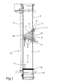
- FIGs. 1-3 show an apparatus 1 for a sorting system 10 comprising an activating member 2, a fastening bracket 3, and a discharge arm 4 which at an end part 5 is pivotally connected with the fastening bracket 3 at a side 6 of a conveyor 7.
- the discharge arm 4 can be swung between a passive position 9 approximately parallel to said side 6 of the conveyor 7 and a number of active angular positions 8 in relation to a conveying direction A of the conveyor 7.
- Fig. 1 shows an item 11 placed along an opposite side edge 13 of the conveyor 7.
- the discharge arms is turned to the angular position 8a.
- the item 11 hits the spoon-formed front 12 of the discharge arm 4 whereby the item either is thrown to the discharge position B or is led to discharge position B by the discharge arm 4 when the discharge arm 4 is swung back to its passive position 9.
- Fig. 2 shows an item 11 placed approximately in the middle of the conveyor 7 where the discharge arm 4 is turned to the angular position 8b in order to guide the item 11 to a discharge position C.
- Fig. 3 shows an item 11 placed close to the edge 6 of the conveyor 7 where the discharge arm 4 is turned to the angular position 8c in order to guide the item 11 to a discharge position D.
- the three figures show that by means of an apparatus 1 it is possible to have an item 11 conveyed to three different discharge position B, C, and D by turning the discharge arm 4 into different angular positions 8a, 8b, and 8c. It will furthermore be possible to turn the discharge arm 4 to angular positions 8 so that the item 11, irrespective of is lateral position on the conveyor 7, will be led to the same discharge position, for example discharge position C.
- sensors 16 are placed which register the lateral and longitudinal position of the item 11 on the conveyor 7.
- the sensors 16 are preferably placed on a transverse bridge across the conveyor 7, and they may as an alternative or as a supplement be placed along the side of the conveyor 7.
- the sensors in the form of photoelectric sensors and/or laser sensors are placed on a three-dimensional bridge extending slopingly across the conveyor 7, or extending both transversely of and along the conveyor 7.
Landscapes
- Engineering & Computer Science (AREA)
- Mechanical Engineering (AREA)
- Sorting Of Articles (AREA)
- Branching, Merging, And Special Transfer Between Conveyors (AREA)
- Separation, Sorting, Adjustment, Or Bending Of Sheets To Be Conveyed (AREA)
- Discharge Of Articles From Conveyors (AREA)
Applications Claiming Priority (2)
| Application Number | Priority Date | Filing Date | Title |
|---|---|---|---|
| DKPA200300614 | 2003-04-24 | ||
| PCT/DK2004/000286 WO2004094279A1 (en) | 2003-04-24 | 2004-04-26 | Apparatus for a sorting system and method for sorting |
Publications (2)
| Publication Number | Publication Date |
|---|---|
| EP1625088A1 EP1625088A1 (en) | 2006-02-15 |
| EP1625088B1 true EP1625088B1 (en) | 2007-06-13 |
Family
ID=33305609
Family Applications (1)
| Application Number | Title | Priority Date | Filing Date |
|---|---|---|---|
| EP04729409A Revoked EP1625088B1 (en) | 2003-04-24 | 2004-04-26 | Apparatus for a sorting system and method for sorting |
Country Status (7)
| Country | Link |
|---|---|
| US (1) | US7469780B2 (da) |
| EP (1) | EP1625088B1 (da) |
| AT (1) | ATE364567T1 (da) |
| DE (1) | DE602004006990T2 (da) |
| DK (1) | DK1625088T3 (da) |
| ES (1) | ES2288682T3 (da) |
| WO (1) | WO2004094279A1 (da) |
Cited By (1)
| Publication number | Priority date | Publication date | Assignee | Title |
|---|---|---|---|---|
| CN103950714A (zh) * | 2014-01-13 | 2014-07-30 | 上海三载机械制造有限公司 | 一种能自动铺料的输送系统 |
Families Citing this family (10)
| Publication number | Priority date | Publication date | Assignee | Title |
|---|---|---|---|---|
| WO1999040883A2 (en) * | 1998-02-11 | 1999-08-19 | Faller Douglas V | Compositions and methods for the treatment of cystic fibrosis |
| NL2000404C2 (nl) | 2006-12-22 | 2008-06-25 | Ambaflex Internat B V | Transportinrichting. |
| US8149804B2 (en) | 2008-04-04 | 2012-04-03 | Intel Corporation | Multi-transceiver wireless communication device and methods for operating during device discovery and connection establishment |
| US7757840B2 (en) * | 2008-06-23 | 2010-07-20 | Unique Metal Designs, Inc. | Conveyor wear bar assembly |
| US7963385B2 (en) * | 2008-08-06 | 2011-06-21 | Pteris Global Ltd. | High speed diverter |
| DE102015111577A1 (de) | 2015-07-16 | 2017-01-19 | Ewab International Ag | Elektrische Weicheneinrichtung für automatische Fördervorrichtungen |
| CN108557457B (zh) * | 2018-05-18 | 2024-01-02 | 湖北理工学院 | 一种废弃微处理器芯片质量检测与自动分拣装置 |
| US20200109010A1 (en) * | 2018-10-08 | 2020-04-09 | Siemens Logistics Llc | Reciprocating acceleration signature monitoring and trend analysis system |
| US11352217B2 (en) * | 2018-10-08 | 2022-06-07 | Siemens Logistics Llc | Reciprocating motion signature monitoring and trend analysis system |
| CN109850555B (zh) * | 2018-12-07 | 2024-01-02 | 无锡先导智能装备股份有限公司 | 电池生产设备及其取样装置 |
Family Cites Families (9)
| Publication number | Priority date | Publication date | Assignee | Title |
|---|---|---|---|---|
| CA1257557A (en) | 1983-03-01 | 1989-07-18 | Rudolf W. Voss | Conveyor deflector mechanism |
| US4564105A (en) * | 1983-12-29 | 1986-01-14 | Lear Siegler, Inc. | Tilted spiral article diverter |
| US4576117A (en) * | 1984-06-25 | 1986-03-18 | A. O. Smith Harvestore Products, Inc. | Livestock feeding apparatus |
| SU1461719A1 (ru) * | 1987-07-13 | 1989-02-28 | В.И.Ць ганков и Н.В.Цымбалюк | Устройство дл промежуточной разгрузки ленточного конвейера |
| US6041910A (en) * | 1997-09-22 | 2000-03-28 | Jervis B. Webb Company | Baggage pusher device and system |
| US5655643A (en) * | 1996-05-08 | 1997-08-12 | United Parcel Service Of America, Inc. | High speed, compound, belted diverter and method of operating same |
| DE19843623C2 (de) | 1998-09-23 | 2000-07-13 | Siemens Ag | Verteilvorrichtung für Stückgut |
| US6220422B1 (en) * | 1998-12-28 | 2001-04-24 | G & T Conveyor Company, Inc. | Rotary articulated pusher for removing items, such as luggage, from a conveyor belt |
| US6822181B2 (en) | 2001-06-27 | 2004-11-23 | Labatt Brewing Company Limited | Container diverter |
-
2004
- 2004-04-26 DK DK04729409T patent/DK1625088T3/da active
- 2004-04-26 DE DE602004006990T patent/DE602004006990T2/de not_active Expired - Lifetime
- 2004-04-26 AT AT04729409T patent/ATE364567T1/de not_active IP Right Cessation
- 2004-04-26 US US10/554,221 patent/US7469780B2/en not_active Expired - Lifetime
- 2004-04-26 ES ES04729409T patent/ES2288682T3/es not_active Expired - Lifetime
- 2004-04-26 WO PCT/DK2004/000286 patent/WO2004094279A1/en not_active Ceased
- 2004-04-26 EP EP04729409A patent/EP1625088B1/en not_active Revoked
Cited By (1)
| Publication number | Priority date | Publication date | Assignee | Title |
|---|---|---|---|---|
| CN103950714A (zh) * | 2014-01-13 | 2014-07-30 | 上海三载机械制造有限公司 | 一种能自动铺料的输送系统 |
Also Published As
| Publication number | Publication date |
|---|---|
| US20070023258A1 (en) | 2007-02-01 |
| EP1625088A1 (en) | 2006-02-15 |
| DE602004006990T2 (de) | 2008-02-21 |
| DK1625088T3 (da) | 2007-10-15 |
| ATE364567T1 (de) | 2007-07-15 |
| ES2288682T3 (es) | 2008-01-16 |
| WO2004094279A1 (en) | 2004-11-04 |
| US7469780B2 (en) | 2008-12-30 |
| DE602004006990D1 (de) | 2007-07-26 |
Similar Documents
| Publication | Publication Date | Title |
|---|---|---|
| EP1625088B1 (en) | Apparatus for a sorting system and method for sorting | |
| US10358298B2 (en) | Slide sorter pop-up diverting conveyor with transfer rate based on article characteristics | |
| KR102048330B1 (ko) | 분류 기계에 물품을 공급하기 위한 장치 및 분류 기계 | |
| CA1133610A (en) | Conveyor sorting system | |
| US10773897B2 (en) | Off-loading, typing and item separation system | |
| US20190193945A1 (en) | Vision based article typing and sorting system | |
| CA2451016C (en) | Method and apparatus for measuring or estimating the center of gravity, flexibility or length of an object and diverting such object on a high-speed conveyor | |
| EP0811567B1 (en) | Crossbelt sortation system | |
| EP3621904A2 (en) | Vision based article typing and sorting system | |
| CA1308691C (en) | System and process for sorting and conveying articles | |
| CN111770798A (zh) | 具有球板的自动分拣系统及其使用方法 | |
| CA2314251A1 (en) | Article classifying system and article dimension measuring apparatus | |
| WO2001074693A1 (en) | Hold and release singulating conveyor | |
| EP0752381B1 (en) | Device for monitoring the movement of the loading/unloading belt of a transportation carriage, especially for sorting apparatuses | |
| WO2004076319A1 (en) | Method and device for re-aligning items on a conveyor | |
| CN115959421A (zh) | 运输装置 | |
| KR20160076292A (ko) | 물품 자동 분류시스템의 인덕션-캐리어 실시간 동기제어방법 | |
| US5193686A (en) | Apparatus for loading articles | |
| US6580038B1 (en) | Static weighing system | |
| RU2743623C1 (ru) | Сортировочная система и способ сортировки объектов | |
| CN113289912B (zh) | 一种薄型物料的分拣仓库 | |
| JPH01152304A (ja) | 搬送区間の対象物の測定方法及びその装置 | |
| JPH01130769A (ja) | 選果機の分級制御装置 | |
| CA2325608C (en) | Mail thickness measuring apparatus | |
| JPS5940121A (ja) | 秤量装置 |
Legal Events
| Date | Code | Title | Description |
|---|---|---|---|
| PUAI | Public reference made under article 153(3) epc to a published international application that has entered the european phase |
Free format text: ORIGINAL CODE: 0009012 |
|
| 17P | Request for examination filed |
Effective date: 20051111 |
|
| AK | Designated contracting states |
Kind code of ref document: A1 Designated state(s): AT BE BG CH CY CZ DE DK EE ES FI FR GB GR HU IE IT LI LU MC NL PL PT RO SE SI SK TR |
|
| DAX | Request for extension of the european patent (deleted) | ||
| GRAP | Despatch of communication of intention to grant a patent |
Free format text: ORIGINAL CODE: EPIDOSNIGR1 |
|
| GRAS | Grant fee paid |
Free format text: ORIGINAL CODE: EPIDOSNIGR3 |
|
| GRAA | (expected) grant |
Free format text: ORIGINAL CODE: 0009210 |
|
| AK | Designated contracting states |
Kind code of ref document: B1 Designated state(s): AT BE BG CH CY CZ DE DK EE ES FI FR GB GR HU IE IT LI LU MC NL PL PT RO SE SI SK TR |
|
| PG25 | Lapsed in a contracting state [announced via postgrant information from national office to epo] |
Ref country code: LI Free format text: LAPSE BECAUSE OF FAILURE TO SUBMIT A TRANSLATION OF THE DESCRIPTION OR TO PAY THE FEE WITHIN THE PRESCRIBED TIME-LIMIT Effective date: 20070613 Ref country code: CH Free format text: LAPSE BECAUSE OF FAILURE TO SUBMIT A TRANSLATION OF THE DESCRIPTION OR TO PAY THE FEE WITHIN THE PRESCRIBED TIME-LIMIT Effective date: 20070613 |
|
| REG | Reference to a national code |
Ref country code: GB Ref legal event code: FG4D |
|
| RIN1 | Information on inventor provided before grant (corrected) |
Inventor name: BANG, MICHAEL |
|
| RAP2 | Party data changed (patent owner data changed or rights of a patent transferred) |
Owner name: LINCO FOOD SYSTEMS A/S |
|
| REG | Reference to a national code |
Ref country code: CH Ref legal event code: EP |
|
| REG | Reference to a national code |
Ref country code: IE Ref legal event code: FG4D |
|
| REF | Corresponds to: |
Ref document number: 602004006990 Country of ref document: DE Date of ref document: 20070726 Kind code of ref document: P |
|
| NLT2 | Nl: modifications (of names), taken from the european patent patent bulletin |
Owner name: LINCO FOOD SYSTEMS A/S Effective date: 20070620 |
|
| PG25 | Lapsed in a contracting state [announced via postgrant information from national office to epo] |
Ref country code: SE Free format text: LAPSE BECAUSE OF FAILURE TO SUBMIT A TRANSLATION OF THE DESCRIPTION OR TO PAY THE FEE WITHIN THE PRESCRIBED TIME-LIMIT Effective date: 20070913 |
|
| REG | Reference to a national code |
Ref country code: DK Ref legal event code: T3 |
|
| ET | Fr: translation filed | ||
| PG25 | Lapsed in a contracting state [announced via postgrant information from national office to epo] |
Ref country code: AT Free format text: LAPSE BECAUSE OF FAILURE TO SUBMIT A TRANSLATION OF THE DESCRIPTION OR TO PAY THE FEE WITHIN THE PRESCRIBED TIME-LIMIT Effective date: 20070613 Ref country code: PL Free format text: LAPSE BECAUSE OF FAILURE TO SUBMIT A TRANSLATION OF THE DESCRIPTION OR TO PAY THE FEE WITHIN THE PRESCRIBED TIME-LIMIT Effective date: 20070613 |
|
| REG | Reference to a national code |
Ref country code: CH Ref legal event code: PL |
|
| REG | Reference to a national code |
Ref country code: ES Ref legal event code: FG2A Ref document number: 2288682 Country of ref document: ES Kind code of ref document: T3 |
|
| PG25 | Lapsed in a contracting state [announced via postgrant information from national office to epo] |
Ref country code: BG Free format text: LAPSE BECAUSE OF FAILURE TO SUBMIT A TRANSLATION OF THE DESCRIPTION OR TO PAY THE FEE WITHIN THE PRESCRIBED TIME-LIMIT Effective date: 20070913 Ref country code: CZ Free format text: LAPSE BECAUSE OF FAILURE TO SUBMIT A TRANSLATION OF THE DESCRIPTION OR TO PAY THE FEE WITHIN THE PRESCRIBED TIME-LIMIT Effective date: 20070613 Ref country code: SI Free format text: LAPSE BECAUSE OF FAILURE TO SUBMIT A TRANSLATION OF THE DESCRIPTION OR TO PAY THE FEE WITHIN THE PRESCRIBED TIME-LIMIT Effective date: 20070613 Ref country code: PT Free format text: LAPSE BECAUSE OF FAILURE TO SUBMIT A TRANSLATION OF THE DESCRIPTION OR TO PAY THE FEE WITHIN THE PRESCRIBED TIME-LIMIT Effective date: 20071113 |
|
| PG25 | Lapsed in a contracting state [announced via postgrant information from national office to epo] |
Ref country code: SK Free format text: LAPSE BECAUSE OF FAILURE TO SUBMIT A TRANSLATION OF THE DESCRIPTION OR TO PAY THE FEE WITHIN THE PRESCRIBED TIME-LIMIT Effective date: 20070613 |
|
| PLBI | Opposition filed |
Free format text: ORIGINAL CODE: 0009260 |
|
| PLAX | Notice of opposition and request to file observation + time limit sent |
Free format text: ORIGINAL CODE: EPIDOSNOBS2 |
|
| 26 | Opposition filed |
Opponent name: STORK PMT B.V. Effective date: 20080313 |
|
| PG25 | Lapsed in a contracting state [announced via postgrant information from national office to epo] |
Ref country code: GR Free format text: LAPSE BECAUSE OF FAILURE TO SUBMIT A TRANSLATION OF THE DESCRIPTION OR TO PAY THE FEE WITHIN THE PRESCRIBED TIME-LIMIT Effective date: 20070914 |
|
| PG25 | Lapsed in a contracting state [announced via postgrant information from national office to epo] |
Ref country code: RO Free format text: LAPSE BECAUSE OF FAILURE TO SUBMIT A TRANSLATION OF THE DESCRIPTION OR TO PAY THE FEE WITHIN THE PRESCRIBED TIME-LIMIT Effective date: 20070613 |
|
| NLR1 | Nl: opposition has been filed with the epo |
Opponent name: STORK PMT B.V. |
|
| PLBB | Reply of patent proprietor to notice(s) of opposition received |
Free format text: ORIGINAL CODE: EPIDOSNOBS3 |
|
| PG25 | Lapsed in a contracting state [announced via postgrant information from national office to epo] |
Ref country code: MC Free format text: LAPSE BECAUSE OF NON-PAYMENT OF DUE FEES Effective date: 20080430 |
|
| PG25 | Lapsed in a contracting state [announced via postgrant information from national office to epo] |
Ref country code: EE Free format text: LAPSE BECAUSE OF FAILURE TO SUBMIT A TRANSLATION OF THE DESCRIPTION OR TO PAY THE FEE WITHIN THE PRESCRIBED TIME-LIMIT Effective date: 20070613 |
|
| PG25 | Lapsed in a contracting state [announced via postgrant information from national office to epo] |
Ref country code: FI Free format text: LAPSE BECAUSE OF FAILURE TO SUBMIT A TRANSLATION OF THE DESCRIPTION OR TO PAY THE FEE WITHIN THE PRESCRIBED TIME-LIMIT Effective date: 20070613 |
|
| PG25 | Lapsed in a contracting state [announced via postgrant information from national office to epo] |
Ref country code: IE Free format text: LAPSE BECAUSE OF NON-PAYMENT OF DUE FEES Effective date: 20080428 |
|
| PG25 | Lapsed in a contracting state [announced via postgrant information from national office to epo] |
Ref country code: CY Free format text: LAPSE BECAUSE OF FAILURE TO SUBMIT A TRANSLATION OF THE DESCRIPTION OR TO PAY THE FEE WITHIN THE PRESCRIBED TIME-LIMIT Effective date: 20070613 |
|
| APBM | Appeal reference recorded |
Free format text: ORIGINAL CODE: EPIDOSNREFNO |
|
| APBP | Date of receipt of notice of appeal recorded |
Free format text: ORIGINAL CODE: EPIDOSNNOA2O |
|
| APAH | Appeal reference modified |
Free format text: ORIGINAL CODE: EPIDOSCREFNO |
|
| APBQ | Date of receipt of statement of grounds of appeal recorded |
Free format text: ORIGINAL CODE: EPIDOSNNOA3O |
|
| PG25 | Lapsed in a contracting state [announced via postgrant information from national office to epo] |
Ref country code: HU Free format text: LAPSE BECAUSE OF FAILURE TO SUBMIT A TRANSLATION OF THE DESCRIPTION OR TO PAY THE FEE WITHIN THE PRESCRIBED TIME-LIMIT Effective date: 20071214 Ref country code: LU Free format text: LAPSE BECAUSE OF NON-PAYMENT OF DUE FEES Effective date: 20080426 |
|
| PG25 | Lapsed in a contracting state [announced via postgrant information from national office to epo] |
Ref country code: TR Free format text: LAPSE BECAUSE OF FAILURE TO SUBMIT A TRANSLATION OF THE DESCRIPTION OR TO PAY THE FEE WITHIN THE PRESCRIBED TIME-LIMIT Effective date: 20070613 |
|
| PGFP | Annual fee paid to national office [announced via postgrant information from national office to epo] |
Ref country code: ES Payment date: 20120410 Year of fee payment: 9 |
|
| REG | Reference to a national code |
Ref country code: DE Ref legal event code: R103 Ref document number: 602004006990 Country of ref document: DE Ref country code: DE Ref legal event code: R064 Ref document number: 602004006990 Country of ref document: DE |
|
| APBU | Appeal procedure closed |
Free format text: ORIGINAL CODE: EPIDOSNNOA9O |
|
| PGFP | Annual fee paid to national office [announced via postgrant information from national office to epo] |
Ref country code: DE Payment date: 20130429 Year of fee payment: 10 Ref country code: BE Payment date: 20130429 Year of fee payment: 10 Ref country code: GB Payment date: 20130429 Year of fee payment: 10 Ref country code: DK Payment date: 20130429 Year of fee payment: 10 |
|
| PGFP | Annual fee paid to national office [announced via postgrant information from national office to epo] |
Ref country code: FR Payment date: 20130506 Year of fee payment: 10 Ref country code: NL Payment date: 20130426 Year of fee payment: 10 Ref country code: IT Payment date: 20130422 Year of fee payment: 10 |
|
| RDAF | Communication despatched that patent is revoked |
Free format text: ORIGINAL CODE: EPIDOSNREV1 |
|
| RDAG | Patent revoked |
Free format text: ORIGINAL CODE: 0009271 |
|
| STAA | Information on the status of an ep patent application or granted ep patent |
Free format text: STATUS: PATENT REVOKED |
|
| 27W | Patent revoked |
Effective date: 20130516 |
|
| GBPR | Gb: patent revoked under art. 102 of the ep convention designating the uk as contracting state |
Effective date: 20130516 |
|
| REG | Reference to a national code |
Ref country code: DE Ref legal event code: R107 Ref document number: 602004006990 Country of ref document: DE Effective date: 20140109 |