EP1625283B2 - Einlaufbelag für gasturbinen - Google Patents
Einlaufbelag für gasturbinen Download PDFInfo
- Publication number
- EP1625283B2 EP1625283B2 EP04728101.9A EP04728101A EP1625283B2 EP 1625283 B2 EP1625283 B2 EP 1625283B2 EP 04728101 A EP04728101 A EP 04728101A EP 1625283 B2 EP1625283 B2 EP 1625283B2
- Authority
- EP
- European Patent Office
- Prior art keywords
- inlet lining
- housing
- gas turbine
- coating
- inlet
- Prior art date
- Legal status (The legal status is an assumption and is not a legal conclusion. Google has not performed a legal analysis and makes no representation as to the accuracy of the status listed.)
- Expired - Lifetime
Links
- 239000011248 coating agent Substances 0.000 title claims description 7
- 238000000576 coating method Methods 0.000 title claims description 7
- 229910052746 lanthanum Inorganic materials 0.000 claims description 11
- FZLIPJUXYLNCLC-UHFFFAOYSA-N lanthanum atom Chemical compound [La] FZLIPJUXYLNCLC-UHFFFAOYSA-N 0.000 claims description 11
- 239000000463 material Substances 0.000 claims description 8
- 239000010410 layer Substances 0.000 description 19
- MCMNRKCIXSYSNV-UHFFFAOYSA-N Zirconium dioxide Chemical compound O=[Zr]=O MCMNRKCIXSYSNV-UHFFFAOYSA-N 0.000 description 7
- 238000005299 abrasion Methods 0.000 description 5
- RVTZCBVAJQQJTK-UHFFFAOYSA-N oxygen(2-);zirconium(4+) Chemical compound [O-2].[O-2].[Zr+4] RVTZCBVAJQQJTK-UHFFFAOYSA-N 0.000 description 3
- 239000002356 single layer Substances 0.000 description 3
- 238000004519 manufacturing process Methods 0.000 description 2
- 238000007789 sealing Methods 0.000 description 2
- 238000007751 thermal spraying Methods 0.000 description 2
- 241000792859 Enema Species 0.000 description 1
- 230000015572 biosynthetic process Effects 0.000 description 1
- 239000002131 composite material Substances 0.000 description 1
- 230000007797 corrosion Effects 0.000 description 1
- 238000005260 corrosion Methods 0.000 description 1
- 239000013078 crystal Substances 0.000 description 1
- 230000001419 dependent effect Effects 0.000 description 1
- 239000007920 enema Substances 0.000 description 1
- 229940095399 enema Drugs 0.000 description 1
- 230000003628 erosive effect Effects 0.000 description 1
- 238000010438 heat treatment Methods 0.000 description 1
- 238000009413 insulation Methods 0.000 description 1
- 239000012774 insulation material Substances 0.000 description 1
- 239000000314 lubricant Substances 0.000 description 1
- 238000012423 maintenance Methods 0.000 description 1
- 239000002245 particle Substances 0.000 description 1
- 230000008092 positive effect Effects 0.000 description 1
- 239000013535 sea water Substances 0.000 description 1
- 230000035939 shock Effects 0.000 description 1
- 238000005245 sintering Methods 0.000 description 1
- 239000012720 thermal barrier coating Substances 0.000 description 1
Images

Classifications
-
- F—MECHANICAL ENGINEERING; LIGHTING; HEATING; WEAPONS; BLASTING
- F01—MACHINES OR ENGINES IN GENERAL; ENGINE PLANTS IN GENERAL; STEAM ENGINES
- F01D—NON-POSITIVE DISPLACEMENT MACHINES OR ENGINES, e.g. STEAM TURBINES
- F01D5/00—Blades; Blade-carrying members; Heating, heat-insulating, cooling or antivibration means on the blades or the members
- F01D5/12—Blades
- F01D5/14—Form or construction
- F01D5/20—Specially-shaped blade tips to seal space between tips and stator
-
- C—CHEMISTRY; METALLURGY
- C23—COATING METALLIC MATERIAL; COATING MATERIAL WITH METALLIC MATERIAL; CHEMICAL SURFACE TREATMENT; DIFFUSION TREATMENT OF METALLIC MATERIAL; COATING BY VACUUM EVAPORATION, BY SPUTTERING, BY ION IMPLANTATION OR BY CHEMICAL VAPOUR DEPOSITION, IN GENERAL; INHIBITING CORROSION OF METALLIC MATERIAL OR INCRUSTATION IN GENERAL
- C23C—COATING METALLIC MATERIAL; COATING MATERIAL WITH METALLIC MATERIAL; SURFACE TREATMENT OF METALLIC MATERIAL BY DIFFUSION INTO THE SURFACE, BY CHEMICAL CONVERSION OR SUBSTITUTION; COATING BY VACUUM EVAPORATION, BY SPUTTERING, BY ION IMPLANTATION OR BY CHEMICAL VAPOUR DEPOSITION, IN GENERAL
- C23C28/00—Coating for obtaining at least two superposed coatings either by methods not provided for in a single one of groups C23C2/00 - C23C26/00 or by combinations of methods provided for in subclasses C23C and C25C or C25D
- C23C28/04—Coating for obtaining at least two superposed coatings either by methods not provided for in a single one of groups C23C2/00 - C23C26/00 or by combinations of methods provided for in subclasses C23C and C25C or C25D only coatings of inorganic non-metallic material
- C23C28/042—Coating for obtaining at least two superposed coatings either by methods not provided for in a single one of groups C23C2/00 - C23C26/00 or by combinations of methods provided for in subclasses C23C and C25C or C25D only coatings of inorganic non-metallic material including a refractory ceramic layer, e.g. refractory metal oxides, ZrO2, rare earth oxides
-
- C—CHEMISTRY; METALLURGY
- C23—COATING METALLIC MATERIAL; COATING MATERIAL WITH METALLIC MATERIAL; CHEMICAL SURFACE TREATMENT; DIFFUSION TREATMENT OF METALLIC MATERIAL; COATING BY VACUUM EVAPORATION, BY SPUTTERING, BY ION IMPLANTATION OR BY CHEMICAL VAPOUR DEPOSITION, IN GENERAL; INHIBITING CORROSION OF METALLIC MATERIAL OR INCRUSTATION IN GENERAL
- C23C—COATING METALLIC MATERIAL; COATING MATERIAL WITH METALLIC MATERIAL; SURFACE TREATMENT OF METALLIC MATERIAL BY DIFFUSION INTO THE SURFACE, BY CHEMICAL CONVERSION OR SUBSTITUTION; COATING BY VACUUM EVAPORATION, BY SPUTTERING, BY ION IMPLANTATION OR BY CHEMICAL VAPOUR DEPOSITION, IN GENERAL
- C23C28/00—Coating for obtaining at least two superposed coatings either by methods not provided for in a single one of groups C23C2/00 - C23C26/00 or by combinations of methods provided for in subclasses C23C and C25C or C25D
- C23C28/04—Coating for obtaining at least two superposed coatings either by methods not provided for in a single one of groups C23C2/00 - C23C26/00 or by combinations of methods provided for in subclasses C23C and C25C or C25D only coatings of inorganic non-metallic material
- C23C28/044—Coating for obtaining at least two superposed coatings either by methods not provided for in a single one of groups C23C2/00 - C23C26/00 or by combinations of methods provided for in subclasses C23C and C25C or C25D only coatings of inorganic non-metallic material coatings specially adapted for cutting tools or wear applications
-
- C—CHEMISTRY; METALLURGY
- C23—COATING METALLIC MATERIAL; COATING MATERIAL WITH METALLIC MATERIAL; CHEMICAL SURFACE TREATMENT; DIFFUSION TREATMENT OF METALLIC MATERIAL; COATING BY VACUUM EVAPORATION, BY SPUTTERING, BY ION IMPLANTATION OR BY CHEMICAL VAPOUR DEPOSITION, IN GENERAL; INHIBITING CORROSION OF METALLIC MATERIAL OR INCRUSTATION IN GENERAL
- C23C—COATING METALLIC MATERIAL; COATING MATERIAL WITH METALLIC MATERIAL; SURFACE TREATMENT OF METALLIC MATERIAL BY DIFFUSION INTO THE SURFACE, BY CHEMICAL CONVERSION OR SUBSTITUTION; COATING BY VACUUM EVAPORATION, BY SPUTTERING, BY ION IMPLANTATION OR BY CHEMICAL VAPOUR DEPOSITION, IN GENERAL
- C23C28/00—Coating for obtaining at least two superposed coatings either by methods not provided for in a single one of groups C23C2/00 - C23C26/00 or by combinations of methods provided for in subclasses C23C and C25C or C25D
- C23C28/30—Coatings combining at least one metallic layer and at least one inorganic non-metallic layer
- C23C28/32—Coatings combining at least one metallic layer and at least one inorganic non-metallic layer including at least one pure metallic layer
- C23C28/322—Coatings combining at least one metallic layer and at least one inorganic non-metallic layer including at least one pure metallic layer only coatings of metal elements only
-
- C—CHEMISTRY; METALLURGY
- C23—COATING METALLIC MATERIAL; COATING MATERIAL WITH METALLIC MATERIAL; CHEMICAL SURFACE TREATMENT; DIFFUSION TREATMENT OF METALLIC MATERIAL; COATING BY VACUUM EVAPORATION, BY SPUTTERING, BY ION IMPLANTATION OR BY CHEMICAL VAPOUR DEPOSITION, IN GENERAL; INHIBITING CORROSION OF METALLIC MATERIAL OR INCRUSTATION IN GENERAL
- C23C—COATING METALLIC MATERIAL; COATING MATERIAL WITH METALLIC MATERIAL; SURFACE TREATMENT OF METALLIC MATERIAL BY DIFFUSION INTO THE SURFACE, BY CHEMICAL CONVERSION OR SUBSTITUTION; COATING BY VACUUM EVAPORATION, BY SPUTTERING, BY ION IMPLANTATION OR BY CHEMICAL VAPOUR DEPOSITION, IN GENERAL
- C23C28/00—Coating for obtaining at least two superposed coatings either by methods not provided for in a single one of groups C23C2/00 - C23C26/00 or by combinations of methods provided for in subclasses C23C and C25C or C25D
- C23C28/30—Coatings combining at least one metallic layer and at least one inorganic non-metallic layer
- C23C28/34—Coatings combining at least one metallic layer and at least one inorganic non-metallic layer including at least one inorganic non-metallic material layer, e.g. metal carbide, nitride, boride, silicide layer and their mixtures, enamels, phosphates and sulphates
- C23C28/345—Coatings combining at least one metallic layer and at least one inorganic non-metallic layer including at least one inorganic non-metallic material layer, e.g. metal carbide, nitride, boride, silicide layer and their mixtures, enamels, phosphates and sulphates with at least one oxide layer
-
- C—CHEMISTRY; METALLURGY
- C23—COATING METALLIC MATERIAL; COATING MATERIAL WITH METALLIC MATERIAL; CHEMICAL SURFACE TREATMENT; DIFFUSION TREATMENT OF METALLIC MATERIAL; COATING BY VACUUM EVAPORATION, BY SPUTTERING, BY ION IMPLANTATION OR BY CHEMICAL VAPOUR DEPOSITION, IN GENERAL; INHIBITING CORROSION OF METALLIC MATERIAL OR INCRUSTATION IN GENERAL
- C23C—COATING METALLIC MATERIAL; COATING MATERIAL WITH METALLIC MATERIAL; SURFACE TREATMENT OF METALLIC MATERIAL BY DIFFUSION INTO THE SURFACE, BY CHEMICAL CONVERSION OR SUBSTITUTION; COATING BY VACUUM EVAPORATION, BY SPUTTERING, BY ION IMPLANTATION OR BY CHEMICAL VAPOUR DEPOSITION, IN GENERAL
- C23C28/00—Coating for obtaining at least two superposed coatings either by methods not provided for in a single one of groups C23C2/00 - C23C26/00 or by combinations of methods provided for in subclasses C23C and C25C or C25D
- C23C28/30—Coatings combining at least one metallic layer and at least one inorganic non-metallic layer
- C23C28/34—Coatings combining at least one metallic layer and at least one inorganic non-metallic layer including at least one inorganic non-metallic material layer, e.g. metal carbide, nitride, boride, silicide layer and their mixtures, enamels, phosphates and sulphates
- C23C28/345—Coatings combining at least one metallic layer and at least one inorganic non-metallic layer including at least one inorganic non-metallic material layer, e.g. metal carbide, nitride, boride, silicide layer and their mixtures, enamels, phosphates and sulphates with at least one oxide layer
- C23C28/3455—Coatings combining at least one metallic layer and at least one inorganic non-metallic layer including at least one inorganic non-metallic material layer, e.g. metal carbide, nitride, boride, silicide layer and their mixtures, enamels, phosphates and sulphates with at least one oxide layer with a refractory ceramic layer, e.g. refractory metal oxide, ZrO2, rare earth oxides or a thermal barrier system comprising at least one refractory oxide layer
-
- C—CHEMISTRY; METALLURGY
- C23—COATING METALLIC MATERIAL; COATING MATERIAL WITH METALLIC MATERIAL; CHEMICAL SURFACE TREATMENT; DIFFUSION TREATMENT OF METALLIC MATERIAL; COATING BY VACUUM EVAPORATION, BY SPUTTERING, BY ION IMPLANTATION OR BY CHEMICAL VAPOUR DEPOSITION, IN GENERAL; INHIBITING CORROSION OF METALLIC MATERIAL OR INCRUSTATION IN GENERAL
- C23C—COATING METALLIC MATERIAL; COATING MATERIAL WITH METALLIC MATERIAL; SURFACE TREATMENT OF METALLIC MATERIAL BY DIFFUSION INTO THE SURFACE, BY CHEMICAL CONVERSION OR SUBSTITUTION; COATING BY VACUUM EVAPORATION, BY SPUTTERING, BY ION IMPLANTATION OR BY CHEMICAL VAPOUR DEPOSITION, IN GENERAL
- C23C28/00—Coating for obtaining at least two superposed coatings either by methods not provided for in a single one of groups C23C2/00 - C23C26/00 or by combinations of methods provided for in subclasses C23C and C25C or C25D
- C23C28/30—Coatings combining at least one metallic layer and at least one inorganic non-metallic layer
- C23C28/34—Coatings combining at least one metallic layer and at least one inorganic non-metallic layer including at least one inorganic non-metallic material layer, e.g. metal carbide, nitride, boride, silicide layer and their mixtures, enamels, phosphates and sulphates
- C23C28/347—Coatings combining at least one metallic layer and at least one inorganic non-metallic layer including at least one inorganic non-metallic material layer, e.g. metal carbide, nitride, boride, silicide layer and their mixtures, enamels, phosphates and sulphates with layers adapted for cutting tools or wear applications
-
- C—CHEMISTRY; METALLURGY
- C23—COATING METALLIC MATERIAL; COATING MATERIAL WITH METALLIC MATERIAL; CHEMICAL SURFACE TREATMENT; DIFFUSION TREATMENT OF METALLIC MATERIAL; COATING BY VACUUM EVAPORATION, BY SPUTTERING, BY ION IMPLANTATION OR BY CHEMICAL VAPOUR DEPOSITION, IN GENERAL; INHIBITING CORROSION OF METALLIC MATERIAL OR INCRUSTATION IN GENERAL
- C23C—COATING METALLIC MATERIAL; COATING MATERIAL WITH METALLIC MATERIAL; SURFACE TREATMENT OF METALLIC MATERIAL BY DIFFUSION INTO THE SURFACE, BY CHEMICAL CONVERSION OR SUBSTITUTION; COATING BY VACUUM EVAPORATION, BY SPUTTERING, BY ION IMPLANTATION OR BY CHEMICAL VAPOUR DEPOSITION, IN GENERAL
- C23C30/00—Coating with metallic material characterised only by the composition of the metallic material, i.e. not characterised by the coating process
-
- F—MECHANICAL ENGINEERING; LIGHTING; HEATING; WEAPONS; BLASTING
- F01—MACHINES OR ENGINES IN GENERAL; ENGINE PLANTS IN GENERAL; STEAM ENGINES
- F01D—NON-POSITIVE DISPLACEMENT MACHINES OR ENGINES, e.g. STEAM TURBINES
- F01D11/00—Preventing or minimising internal leakage of working-fluid, e.g. between stages
- F01D11/08—Preventing or minimising internal leakage of working-fluid, e.g. between stages for sealing space between rotor blade tips and stator
- F01D11/12—Preventing or minimising internal leakage of working-fluid, e.g. between stages for sealing space between rotor blade tips and stator using a rubstrip, e.g. erodible. deformable or resiliently-biased part
- F01D11/122—Preventing or minimising internal leakage of working-fluid, e.g. between stages for sealing space between rotor blade tips and stator using a rubstrip, e.g. erodible. deformable or resiliently-biased part with erodable or abradable material
-
- F—MECHANICAL ENGINEERING; LIGHTING; HEATING; WEAPONS; BLASTING
- F01—MACHINES OR ENGINES IN GENERAL; ENGINE PLANTS IN GENERAL; STEAM ENGINES
- F01D—NON-POSITIVE DISPLACEMENT MACHINES OR ENGINES, e.g. STEAM TURBINES
- F01D5/00—Blades; Blade-carrying members; Heating, heat-insulating, cooling or antivibration means on the blades or the members
- F01D5/12—Blades
- F01D5/28—Selecting particular materials; Particular measures relating thereto; Measures against erosion or corrosion
- F01D5/288—Protective coatings for blades
-
- F—MECHANICAL ENGINEERING; LIGHTING; HEATING; WEAPONS; BLASTING
- F05—INDEXING SCHEMES RELATING TO ENGINES OR PUMPS IN VARIOUS SUBCLASSES OF CLASSES F01-F04
- F05D—INDEXING SCHEME FOR ASPECTS RELATING TO NON-POSITIVE-DISPLACEMENT MACHINES OR ENGINES, GAS-TURBINES OR JET-PROPULSION PLANTS
- F05D2300/00—Materials; Properties thereof
- F05D2300/10—Metals, alloys or intermetallic compounds
- F05D2300/15—Rare earth metals, i.e. Sc, Y, lanthanides
-
- Y—GENERAL TAGGING OF NEW TECHNOLOGICAL DEVELOPMENTS; GENERAL TAGGING OF CROSS-SECTIONAL TECHNOLOGIES SPANNING OVER SEVERAL SECTIONS OF THE IPC; TECHNICAL SUBJECTS COVERED BY FORMER USPC CROSS-REFERENCE ART COLLECTIONS [XRACs] AND DIGESTS
- Y02—TECHNOLOGIES OR APPLICATIONS FOR MITIGATION OR ADAPTATION AGAINST CLIMATE CHANGE
- Y02T—CLIMATE CHANGE MITIGATION TECHNOLOGIES RELATED TO TRANSPORTATION
- Y02T50/00—Aeronautics or air transport
- Y02T50/60—Efficient propulsion technologies, e.g. for aircraft
Definitions
- the invention relates to a gas turbine with an inlet lining according to the preamble of patent claim 1.
- Gas turbines such as aircraft engines, typically include a plurality of rotating blades and a plurality of fixed vanes, the blades rotating together with a rotor, and wherein the blades and the vanes are enclosed by a fixed housing of the gas turbine.
- gas turbines typically include a plurality of rotating blades and a plurality of fixed vanes, the blades rotating together with a rotor, and wherein the blades and the vanes are enclosed by a fixed housing of the gas turbine.
- sealing systems in aircraft engines.
- Particularly problematic in aircraft engines is the maintenance of a minimum gap between the rotating blades and the stationary housing of a high-pressure gas turbine. Namely, the highest absolute temperatures and temperature gradients occur in high-pressure gas turbines, which makes it difficult to keep the rotating blades clear of the gap to the stationary housing of the compressor.
- the EP 0765 951 B1 discloses an inlet lining for a gas turbine in which the outer layer of the inlet lining, which is in contact with the tips of the blades, is made of zirconia. Another inlet lining is from the U.S. Patent 4,936,745 known.
- the present invention is based on the problem to provide a gas turbine with a novel inlet lining.
- the inlet lining of the gas turbine according to the invention serves to seal a radial gap between a stationary housing of the gas turbine and rotating blades thereof.
- the inlet lining is attached to the housing.
- the inlet lining is designed as a single layer, wherein the one layer of the inlet lining is made of a material having a magnetoplumbite structure, preferably of lanthanum hexaaluminate.
- the outer layer of the inlet lining which first comes into contact with the rotating blades, no longer be made of zirconium dioxide but preferably of lanthanum hexaaluminate.
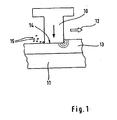
- Fig. 1 shows a highly schematic of a rotating blade 10 of a gas turbine, which rotates relative to a fixed housing 11 in the direction of the arrow 12.
- a fixed housing 11 On the housing 11, an inlet lining 13 is arranged.
- the inlet lining 13 serves to seal a radial gap between a tip or end 14 of the rotating blade 10 and the stationary housing 11.
- the requirements placed on such an inlet lining are very complex.
- the inlet lining must have an optimized abrasion behavior, i. it must be ensured a good chip formation and removability of abrasion.
- no transfer of material to the rotating blades 10 may take place.
- the inlet lining 13 must furthermore have a low frictional resistance.
- the inlet lining 13 must not ignite when rubbed by the rotating blades 10.
- Fig. 1 illustrates that due to the centrifugal forces occurring during operation of the gas turbine and the heating of the gas turbine, the ends 14 of the blades 10 come into contact with the inlet lining 13 and so an abrasion 15 is released. This pulverized abrasion 15 must not cause any damage to the rotating blades 10.
- the inlet lining 13 is made of a material with magnetoplumbite structure, in the illustrated embodiment of lanthanum hexaaluminate.
- Fig. 1 it is a single-layer inlet lining 13, wherein the single layer of the inlet lining 13 is made of the lanthanum hexaaluminate and is applied directly to the housing 11. It is therefore within the meaning of the present invention to use instead of the known from the prior art zirconia lanthanum hexaaluminate for the production of the outer layer of Einlaufbelgen.
- Fig. 2 shows an example that does not belong to the invention. So shows Fig. 2 in turn, a rotating blade 16 which rotates relative to a fixed housing 18 in the direction of the arrow 17. On the stationary housing 18, in turn, an inlet lining 19 is arranged.
- inlet lining 19 of the embodiment according to the Fig. 2 In contrast to the embodiment of Fig. 1 is the inlet lining 19 of the embodiment according to the Fig. 2 but not single-layered, but multi-layered.
- An outer layer 20 of the inlet pad 19, which first comes into contact with the blades 16, according to the invention is again made of lanthanum hexaaluminate.
- a further intermediate layer (not shown) of zirconium dioxide may be arranged.
- This intermediate layer of zirconium dioxide serves to improve the properties of the layer composite, in particular the increase of the service life.
- the outer layer of a multilayer inlet lining which first comes into contact with the rotating blades of the gas turbine, to be made of lanthanum hexaaluminate.
- a so-called tarnish 23 is provided.
- the starting lining 23 comprises a plurality of wedge-shaped elements 24, wherein between two adjacent elements 24 of the starting lining 23 free spaces 25 are formed.
- a sealing system for a gas turbine in which an applied on the housing 18 of the gas turbine, inventive inlet lining 19 is combined with a arranged on the blade tips starting pad 23.
- the principle of the present invention is to fabricate an outer layer of enema pad which contacts tips of the rotating blades from lanthanum hexaaluminate.
- inlet lining With such an inlet lining, particularly positive properties can be achieved. This sets a particularly good abrasion behavior of the inlet lining.
- the other requirements for the inlet lining are also met or positively influenced. For example, the temperature resistance and service life of the inlet coverings is improved.
- inlet lining according to the invention is applied by means of thermal spraying onto the metallic surface of the housing. Details of thermal spraying are familiar to the person skilled in the art.
Landscapes
- Chemical & Material Sciences (AREA)
- Engineering & Computer Science (AREA)
- Mechanical Engineering (AREA)
- Inorganic Chemistry (AREA)
- Materials Engineering (AREA)
- Chemical Kinetics & Catalysis (AREA)
- Metallurgy (AREA)
- Organic Chemistry (AREA)
- General Engineering & Computer Science (AREA)
- Ceramic Engineering (AREA)
- Turbine Rotor Nozzle Sealing (AREA)
Description
- Die Erfindung betrifft eine Gasturbine mit einem Einlaufbelag gemäß dem Oberbegriff des Patentanspruchs 1.
- Gasturbinen, wie zum Beispiel Flugtriebwerke, umfassen in der Regel mehrere rotierende Laufschaufeln sowie mehrere feststehende Leitschaufeln, wobei die Laufschaufeln zusammen mit einem Rotor rotieren und wobei die Laufschaufeln sowie die Leitschaufeln von einem feststehenden Gehäuse der Gasturbine umschlossen sind. Zur Leistungssteigerung eines Flugtriebwerks ist es von Bedeutung, alle Komponenten und Subsysteme zu optimieren. Hierzu zählen auch die sogenannten Dichtsysteme in Flugtriebwerken. Besonders problematisch ist bei Flugtriebwerken die Einhaltung eines minimalen Spalts zwischen den rotierenden Laufschaufeln und dem feststehenden Gehäuse einer Hochdruckgasturbine. Bei Hochdruckgasturbinen treten nämlich die größten absoluten Temperaturen sowie Temperaturengradienten auf, was die Spalthaltung der rotierenden Laufschaufeln zum feststehenden Gehäuse des Verdichters erschwert. Dies liegt unter anderem auch darin begründet, dass bei Verdichterlaufschaufeln auf Deckbänder, wie sie bei Turbinen verwendet werden, verzichtet wird. Wie bereits erwähnt, verfügen Laufschaufeln im Verdichter über kein Deckband. Daher sind Enden bzw. Spitzen der rotierenden Laufschaufeln beim sogenannten Anstreifen in das feststehende Gehäuse einem direkten Reibkontakt mit dem Gehäuse ausgesetzt. Ein solches Anstreifen der Spitzen der Laufschaufeln in das Gehäuse wird bei Einstellung eines minimalen Radialspalts durch Fertigungstoleranzen hervorgerufen. Da durch den Reibkontakt der Spitzen der rotierenden Laufschaufeln an denselben Material abgetragen wird, kann sich über den gesamten Umfang von Gehäuse und Rotor eine unerwünschte Spaltvergrößerung einstellen. Um dies zu vermeiden ist es aus dem Stand der Technik bereits bekannt, die Enden bzw. Spitzen der rotierenden Laufschaufeln mit einem harten Belag oder mit abrasiven Partikeln zu panzern. Eine andere Möglichkeit, den Verschleiß an den Spitzen der rotierenden Laufschaufeln zu vermeiden und für eine optimierte Abdichtung zwischen den Enden bzw. Spitzen der rotierenden Laufschaufeln und dem feststehenden Gehäuse zu sorgen, besteht in der Beschichtung des Gehäuses mit einem sogenannten Einlaufbelag. Bei einem Materialabtrag an einem Einlaufbelag wird der Radialspalt nicht über den gesamten Umfang vergrößert, sondern in der Regel nur sichelförmig. Hierdurch wird ein Leistungsabfall des Triebwerks vermieden. Gehäuse mit einem Einlaufbelag sind aus dem Stand der Technik bekannt.
- Die
EP 0765 951 B1 offenbart einen Einlaufbelag für eine Gasturbine, bei welchem die äußere Schicht bzw. Deckschicht des Einlaufbelags, die mit den Spitzen der Laufschaufeln in Kontakt steht, aus Zirkondioxid hergestellt ist. Ein weiterer Einlaufbelag ist aus demUS-Patent 4,936,745 bekannt. - Aus der
EP-A-1 060 281 ist es bekannt, ein Material mit Magnetoplumbit-Struktur, vorzugsweise Lanthan-Hexaaluminat, als Wärmedämmmaterial zu verwenden. Wenn die Struktur so eingestellt wird, dass alle Stellen im Kristallgitter besetzt sind, ist diese besonders beständig gegen ein Zusammensintern bei hohen Temperaturen, weshalb sie sich u. a. als Wärmedämmschicht auf Turbinenschaufeln eignet. Das Dokument gibt keine Hinweise auf andere Anwendungen als zur Wärmedämmung. - Hiervon ausgehend liegt der vorliegenden Erfindung das Problem zu Grunde, eine Gasturbine mit einem neuartigen Einlaufbelag zu schaffen.
- Dieses Problem wird dadurch gelöst, dass die Gasturbine einen Einlaufbelag aufweist, der durch die Merkmale des kennzeichnenden Teils des Patentanspruchs 1 weitergebildet ist.
- Der Einlaufbelag der erfindungsgemäßen Gasturbine dient der Abdichtung eines radialen Spalts zwischen einem feststehenden Gehäuse der Gasturbine und rotierenden Laufschaufeln derselben. Der Einlaufbelag ist an dem Gehäuse angebracht. Erfindungsgemäß ist der Einlaufbelag einschichtig ausgebildet, wobei die eine Schicht des Einlaufbelags aus einem Material mit Magnetoplumbit-Struktur, vorzugsweise aus Lanthan-Hexaaluminat, hergestellt ist. Im Sinne der Erfindung wird demnach vorgeschlagen, die äußere Schicht des Einlaufbelags, die mit den rotierenden Laufschaufeln zuerst in Kontakt kommt, nicht mehr aus Zirkondioxid sondern vorzugsweise aus Lanthan-Hexaaluminat herzustellen.
- Bevorzugte Weiterbildungen der Erfindung ergeben sich aus den abhängigen Unteransprüchen und der nachfolgenden Beschreibung.
- Nachfolgend werden Ausführungsbeispiele der Erfindung, ohne hierauf beschränkt zu sein, an Hand der Zeichnung näher erläutert. In der Zeichnung zeigt:
- Fig. 1:
- eine stark schematisierte Darstellung einer Laufschaufel einer Gasturbine zusammen mit einem Gehäuse der Gasturbine und mit einem auf dem Gehäuse angeordneten Einlaufbelag, und
- Fig. 2:
- eine stark schematisierte Darstellung einer Laufschaufel einer Gasturbine zusammen mit einem Gehäuse der Gasturbine und mit einem auf dem Gehäuse angeordneten, alternativen Einlaufbelag.
-
Fig. 1 zeigt stark schematisiert eine rotierende Laufschaufel 10 einer Gasturbine, die gegenüber einem feststehenden Gehäuse 11 in Richtung des Pfeils 12 rotiert. Auf dem Gehäuse 11 ist ein Einlaufbelag 13 angeordnet. - Der Einlaufbelag 13 dient der Abdichtung eines radialen Spalts zwischen einer Spitze bzw. einem Ende 14 der rotierenden Laufschaufel 10 und dem feststehenden Gehäuse 11. Die Anforderungen, die an einen solchen Einlaufbelag gestellt werden, sind sehr komplex. So muss der Einlaufbelag ein optimiertes Abriebverhalten aufweisen, d.h. es muss eine gute Spanbildung und Entfernbarkeit des Abriebs gewährleistet sein. Weiterhin darf kein Materialübertrag auf die rotierenden Laufschaufeln 10 erfolgen. Der Einlaufbelag 13 muss des weiteren einen niedrigen Reibwiderstand aufweisen. Des weiteren darf sich der Einlaufbelag 13 beim Anstreifen durch die rotierenden Laufschaufeln 10 nicht entzünden. Als weitere Anforderungen, die an den Einlaufbelag 13 gestellt werden, seinen hier die Erosionsbeständigkeit, Temperaturbeständigkeit, Thermowechselbeständigkeit, Korrosionsbeständigkeit gegenüber Schmierstoffen und Meerwasser exemplarisch genannt.
-
Fig. 1 verdeutlicht, dass bedingt durch die beim Betrieb der Gasturbine auftretenden Fliehkräfte und die Erwärmung der Gasturbine die Enden 14 der Laufschaufeln 10 mit dem Einlaufbelag 13 in Kontakt kommen und so ein Abrieb 15 freigesetzt wird. Dieser pulverisierte Abrieb 15 darf keine Beschädigungen an den rotierenden Laufschaufeln 10 hervorrufen. - Es liegt nun im Sinne der hier vorliegenden Erfindung, dass der Einlaufbelag 13 aus aus einem Material mit Magnetoplumbit-Struktur hergestellt ist, im gezeigten Ausführungsbeispiel aus Lanthan-Hexaaluminat. Im Ausführungsbeispiel der
Fig. 1 handelt es sich um einen einschichtigen Einlaufbelag 13, wobei die einzige Schicht des Einlaufbelags 13 aus dem Lanthan-Hexaaluminat hergestellt ist und unmittelbar auf das Gehäuse 11 aufgebracht ist. Es liegt demnach im Sinne der hier vorliegenden Erfindung, anstelle des aus dem Stand der Technik bekannten Zirkondioxids Lanthan-Hexaaluminat für die Herstellung der äußeren Schicht von Einlaufbelegen zu verwenden. -
Fig. 2 zeigt ein Beispiel, das nicht zur Erfindung gehört. So zeigtFig. 2 wiederum eine rotierende Laufschaufel 16, die im Sinne des Pfeils 17 relativ zu einem feststehenden Gehäuse 18 rotiert. Auf dem feststehenden Gehäuse 18 ist wiederum ein Einlaufbelag 19 angeordnet. - Im Unterschied zum Ausführungsbeispiel der
Fig. 1 ist der Einlaufbelag 19 des Ausführungsbeispiels gemäß derFig. 2 jedoch nicht einschichtig, sondern mehrschichtig ausgebildet. Eine äußere Schicht 20 des Einlaufbelags 19, welche zuerst mit den Laufschaufeln 16 in Kontakt tritt, ist erfindungsgemäß wieder aus Lanthan-Hexaaluminat hergestellt. - Zusätzlich ist zwischen der äußeren Schicht 20 und dem Gehäuse 18 eine innenliegende Schicht 21 vorgesehen. Bei der innenliegenden Schicht 21 handelt es sich um eine haftvermittelnde Schicht, um die Haftung zwischen dem Gehäuse 18 und der äußeren Schicht 20 zu verbessern. Die innenliegenden Schicht 21 zur Haftvermittlung kann metallisch ausgebildet sein.
- Zwischen die haftvermittelnde, innenliegende Schicht 21 und die äußere Schicht 20 aus Lanthan-Hexaaluminat kann eine weitere Zwischenschicht (nicht gezeigt) aus Zirkondioxid angeordnet sein. Diese Zwischenschicht aus Zirkondioxid dient der Verbessung der Eigenschaften des Schichtverbunds, insbesondere der Erhöhung der Lebensdauer.
- An dieser Stelle sei darauf hingewiesen, dass selbstverständlich auch drei- oder mehrschichtige Einlaufbelege im Sinne der Erfindung vorgesehen sein können. Im Sinne der Erfindung soll jedoch die äußere Schicht eines mehrschichtigen Einlaufbelags, welche als erste mit den rotierenden Laufschaufeln der Gasturbine in Kontakt tritt, aus Lanthan-Hexaaluminat hergestellt sein.
- Im Ausführungsbeispiel der
Fig. 2 ist an dem Ende 22 bzw. der Spitze der rotierenden Laufschaufel 16 ein sogenannter Anlaufbelag 23 vorgesehen. Bei diesem Anlaufbelag 23 handelt es sich um eine Panzerung der Laufschaufelspitzen. Im gezeigten Ausführungsbeispiel umfasst der Anlaufbelag 23 mehrere keilförmig ausgebildete Elemente 24, wobei zwischen zwei benachbarten Elementen 24 des Anlaufbelags 23 Freiräume 25 ausgebildet sind. Insofern zeigtFig. 2 ein Dichtsystem für eine Gasturbine, bei welchem ein auf dem Gehäuse 18 der Gasturbine aufgebrachter, erfindungsgemäßer Einlaufbelag 19 mit einem auf den Laufschaufelspitzen angeordneten Anlaufbelag 23 kombiniert wird. - Beiden Ausführungsbeispielen der
Fig. 1 und2 ist das erfindungsgemäße Prinzip gemeinsam, eine äußere Schicht eines Einlaufbelags, die mit Spitzen der rotierenden Laufschaufeln in Kontakt tritt, aus Lanthan-Hexaaluminat herzustellen. - Mit einem solchen Einlaufbelag lassen sich besonders positive Eigenschaften erzielen. So stellt sich ein besonders gutes Abriebverhalten des Einlaufbelags ein. Auch die anderen Anforderungen an den Einlaufbelag werden erfüllt bzw. positiv beeinflusst. So wird zum Beispiel die Temperaturbeständigkeit und Lebensdauer der Einlaufbeläge verbessert.
- An dieser Stelle sei darauf hingewiesen, dass der erfindungsgemäße Einlaufbelag mithilfe des thermischen Spritzens auf die metallische Oberfläche des Gehäuses aufgebracht wird. Details des thermischen Spritzens sind dem hier angesprochenen Fachmann geläufig.
Claims (2)
- Gasturbine mit einem Einlaufbelag (13; 19), der zur Abdichtung eines radialen Spalts zwischen einem Gehäuse (11; 18) und rotierenden Laufschaufeln (10; 16) dient, wobei der Einlaufbelag (13; 19) an dem Gehäuse (11; 18) angebracht ist,
dadurch gekennzeichnet, dass
der Einlaufbelag (13; 19) einschichtig ausgebildet ist, wobei die eine Schicht des Einlaufbelags (13; 19) aus einem Material mit Magnetoplumbit-Struktur hergestellt ist. - Gasturbine nach Anspruch 1,
dadurch gekennzeichnet, dass
das Material mit Magnetoplumbit-Struktur als Lanthan-Hexaaluminat ausgeführt ist.
Applications Claiming Priority (2)
| Application Number | Priority Date | Filing Date | Title |
|---|---|---|---|
| DE10322339A DE10322339A1 (de) | 2003-05-17 | 2003-05-17 | Einlaufbelag für Gasturbinen |
| PCT/DE2004/000808 WO2004104378A1 (de) | 2003-05-17 | 2004-04-17 | Einlaufbelag für gasturbinen |
Publications (3)
| Publication Number | Publication Date |
|---|---|
| EP1625283A1 EP1625283A1 (de) | 2006-02-15 |
| EP1625283B1 EP1625283B1 (de) | 2012-05-09 |
| EP1625283B2 true EP1625283B2 (de) | 2015-09-02 |
Family
ID=33394727
Family Applications (1)
| Application Number | Title | Priority Date | Filing Date |
|---|---|---|---|
| EP04728101.9A Expired - Lifetime EP1625283B2 (de) | 2003-05-17 | 2004-04-17 | Einlaufbelag für gasturbinen |
Country Status (4)
| Country | Link |
|---|---|
| US (1) | US20060213435A1 (de) |
| EP (1) | EP1625283B2 (de) |
| DE (1) | DE10322339A1 (de) |
| WO (1) | WO2004104378A1 (de) |
Families Citing this family (8)
| Publication number | Priority date | Publication date | Assignee | Title |
|---|---|---|---|---|
| DE102004009752A1 (de) * | 2004-02-28 | 2005-09-15 | Mtu Aero Engines Gmbh | Schichtsystem |
| DE102004025798A1 (de) * | 2004-05-26 | 2005-12-22 | Mtu Aero Engines Gmbh | Wärmedämmschichtsystem |
| DE102006027728A1 (de) * | 2006-06-16 | 2007-12-20 | Mtu Aero Engines Gmbh | Wärmedämmschicht |
| EP2309098A1 (de) * | 2009-09-30 | 2011-04-13 | Siemens Aktiengesellschaft | Profil und zugehörige Leitschaufel, Laufschaufel, Gasturbine und Strömungsmaschine |
| DE102009055914A1 (de) * | 2009-11-27 | 2011-06-09 | Rolls-Royce Deutschland Ltd & Co Kg | Dichtringe für eine Labyrinthdichtung |
| KR20150129786A (ko) * | 2013-03-07 | 2015-11-20 | 바스프 에스이 | 이산화탄소의 존재 하에 탄화수소를 개질하기 위한 니켈 헥사알루민에이트-함유 촉매 |
| FR3026428B1 (fr) * | 2014-09-30 | 2019-10-25 | Safran Aircraft Engines | Aube de rotor de turbomachine a lechettes radiales |
| FR3065482B1 (fr) * | 2017-04-20 | 2019-07-05 | Safran Aircraft Engines | Element d'anneau d'etancheite pour turbine comportant une cavite inclinee dans un materiau abradable |
Citations (4)
| Publication number | Priority date | Publication date | Assignee | Title |
|---|---|---|---|---|
| US4299865A (en) † | 1979-09-06 | 1981-11-10 | General Motors Corporation | Abradable ceramic seal and method of making same |
| EP0837222A1 (de) † | 1996-10-21 | 1998-04-22 | AlliedSignal Inc. | Spielkontrollvorrichtung im Kompressor einer Gasturbine mit schleifenden Schaufelspitzen und abschleifbarer Statordichtung |
| DE19807163C1 (de) † | 1998-02-20 | 1999-10-28 | Rainer Gadow | Wärmedämmaterial und Verfahren zum Herstellen eines solchen |
| EP1375696A2 (de) † | 2002-06-10 | 2004-01-02 | MTU Aero Engines GmbH | Schichtsystem für die Rotor-/Statordichtung einer Strömungsmaschine |
Family Cites Families (3)
| Publication number | Priority date | Publication date | Assignee | Title |
|---|---|---|---|---|
| US4269903A (en) * | 1979-09-06 | 1981-05-26 | General Motors Corporation | Abradable ceramic seal and method of making same |
| US4936745A (en) * | 1988-12-16 | 1990-06-26 | United Technologies Corporation | Thin abradable ceramic air seal |
| DE10122545A1 (de) * | 2001-05-09 | 2002-11-28 | Deutsch Zentr Luft & Raumfahrt | Wärmedämmmaterial mit im wesentlichen magnetoplumbitischer Kristallstruktur |
-
2003
- 2003-05-17 DE DE10322339A patent/DE10322339A1/de not_active Ceased
-
2004
- 2004-04-17 US US10/552,213 patent/US20060213435A1/en not_active Abandoned
- 2004-04-17 WO PCT/DE2004/000808 patent/WO2004104378A1/de not_active Ceased
- 2004-04-17 EP EP04728101.9A patent/EP1625283B2/de not_active Expired - Lifetime
Patent Citations (4)
| Publication number | Priority date | Publication date | Assignee | Title |
|---|---|---|---|---|
| US4299865A (en) † | 1979-09-06 | 1981-11-10 | General Motors Corporation | Abradable ceramic seal and method of making same |
| EP0837222A1 (de) † | 1996-10-21 | 1998-04-22 | AlliedSignal Inc. | Spielkontrollvorrichtung im Kompressor einer Gasturbine mit schleifenden Schaufelspitzen und abschleifbarer Statordichtung |
| DE19807163C1 (de) † | 1998-02-20 | 1999-10-28 | Rainer Gadow | Wärmedämmaterial und Verfahren zum Herstellen eines solchen |
| EP1375696A2 (de) † | 2002-06-10 | 2004-01-02 | MTU Aero Engines GmbH | Schichtsystem für die Rotor-/Statordichtung einer Strömungsmaschine |
Also Published As
| Publication number | Publication date |
|---|---|
| EP1625283A1 (de) | 2006-02-15 |
| DE10322339A1 (de) | 2004-12-02 |
| WO2004104378A1 (de) | 2004-12-02 |
| US20060213435A1 (en) | 2006-09-28 |
| EP1625283B1 (de) | 2012-05-09 |
Similar Documents
| Publication | Publication Date | Title |
|---|---|---|
| EP1375696B1 (de) | Schichtsystem für die Rotor-/Statordichtung einer Strömungsmaschine | |
| EP1320662B1 (de) | Dichtungsanordnung | |
| DE19962316C2 (de) | Bürstendichtung | |
| WO2013026870A1 (de) | Strömungsmaschine mit beschichteter laufschaufelspitze und beschichtetem innengehäuse | |
| EP2122009A1 (de) | Vorrichtung zum schutz von bauteilen mit brennbarer titanlegierung vor titanfeuer und verfahren zu deren herstellung | |
| WO2002090724A1 (de) | Mantelring | |
| EP1625283B1 (de) | Einlaufbelag für gasturbinen | |
| EP2044293A1 (de) | Gasturbine mit einem mantelringsegment umfassend einen rezirkulationskanal | |
| EP1741876A1 (de) | Schaufel einer Turbomaschine mit einer Schaufelspitzenpanzerung | |
| EP2294286A2 (de) | Deckband für laufschaufeln einer stromungsmaschine | |
| EP1715140A1 (de) | Turbinenschaufel mit einer Deckplatte und einer auf der Deckplatte aufgebrachte Schutzschicht | |
| DE102016201523A1 (de) | Schaufel einer Strömungsmaschine mit Schaufelfusswärmedämmung | |
| EP2737103B1 (de) | Verfahren zum aufbringen einer verschleissschutzschicht auf eine strömungsmaschinenkomponente | |
| EP2647796A1 (de) | Dichtungssystem für eine Strömungsmaschine | |
| EP1654441B1 (de) | Einlaufbelag für Gasturbinen und Verfahren zur Herstellung dieses Einlaufbelags | |
| EP2358979B1 (de) | Axialverdichter für eine gasturbine mit passiver radialspaltkontrolle | |
| EP1766193B1 (de) | Einlaufbelag | |
| EP3093371A2 (de) | Kombination von schaufelspitzenpanzerung und erosionsschutzschicht sowie verfahren zur herstellung derselben | |
| EP2031183B1 (de) | Dampfturbinenwelle mit Wärmedämmschicht | |
| WO2010020210A2 (de) | Laufschaufelsystem für eine laufschaufelreihe einer strömungsmaschine | |
| DE102004050739A1 (de) | Turbomaschine, insbesondere Gasturbine | |
| EP2112334A1 (de) | Außengehäuse für eine Strömungsmaschine | |
| WO2007028353A1 (de) | Strömungsmaschine sowie dichtungselement für eine strömungsmaschine | |
| DE102020209579A1 (de) | Hochdruckkompressorabschnitt für eine strömungsmaschine und entsprechende strömungsmaschine sowie verfahren zur herstellung eines bauteils für den hochdruckkopressorabschnitt aus einem faserverbundwerkstoff | |
| EP2784268A1 (de) | Eine Turbinenschaufelaussendichtung bestehend aus jeweils einer keramischen abrasiven Schicht auf dem Stator und dem Rotor. |
Legal Events
| Date | Code | Title | Description |
|---|---|---|---|
| PUAI | Public reference made under article 153(3) epc to a published international application that has entered the european phase |
Free format text: ORIGINAL CODE: 0009012 |
|
| 17P | Request for examination filed |
Effective date: 20050810 |
|
| AK | Designated contracting states |
Kind code of ref document: A1 Designated state(s): DE FR GB IT |
|
| DAX | Request for extension of the european patent (deleted) | ||
| RBV | Designated contracting states (corrected) |
Designated state(s): DE FR GB IT |
|
| GRAP | Despatch of communication of intention to grant a patent |
Free format text: ORIGINAL CODE: EPIDOSNIGR1 |
|
| RTI1 | Title (correction) |
Free format text: RUNNING-IN COATING FOR GAS TURBINES |
|
| GRAS | Grant fee paid |
Free format text: ORIGINAL CODE: EPIDOSNIGR3 |
|
| GRAA | (expected) grant |
Free format text: ORIGINAL CODE: 0009210 |
|
| AK | Designated contracting states |
Kind code of ref document: B1 Designated state(s): DE FR GB IT |
|
| REG | Reference to a national code |
Ref country code: GB Ref legal event code: FG4D Free format text: NOT ENGLISH |
|
| REG | Reference to a national code |
Ref country code: DE Ref legal event code: R096 Ref document number: 502004013505 Country of ref document: DE Effective date: 20120712 |
|
| PLBI | Opposition filed |
Free format text: ORIGINAL CODE: 0009260 |
|
| 26 | Opposition filed |
Opponent name: SIEMENS AKTIENGESELLSCHAFT Effective date: 20121218 |
|
| REG | Reference to a national code |
Ref country code: DE Ref legal event code: R026 Ref document number: 502004013505 Country of ref document: DE Effective date: 20121218 |
|
| PLAX | Notice of opposition and request to file observation + time limit sent |
Free format text: ORIGINAL CODE: EPIDOSNOBS2 |
|
| PLBB | Reply of patent proprietor to notice(s) of opposition received |
Free format text: ORIGINAL CODE: EPIDOSNOBS3 |
|
| RAP2 | Party data changed (patent owner data changed or rights of a patent transferred) |
Owner name: MTU AERO ENGINES GMBH |
|
| PUAH | Patent maintained in amended form |
Free format text: ORIGINAL CODE: 0009272 |
|
| STAA | Information on the status of an ep patent application or granted ep patent |
Free format text: STATUS: PATENT MAINTAINED AS AMENDED |
|
| 27A | Patent maintained in amended form |
Effective date: 20150902 |
|
| AK | Designated contracting states |
Kind code of ref document: B2 Designated state(s): DE FR GB IT |
|
| REG | Reference to a national code |
Ref country code: DE Ref legal event code: R102 Ref document number: 502004013505 Country of ref document: DE |
|
| REG | Reference to a national code |
Ref country code: FR Ref legal event code: PLFP Year of fee payment: 13 |
|
| REG | Reference to a national code |
Ref country code: FR Ref legal event code: PLFP Year of fee payment: 14 |
|
| REG | Reference to a national code |
Ref country code: FR Ref legal event code: PLFP Year of fee payment: 15 |
|
| PGFP | Annual fee paid to national office [announced via postgrant information from national office to epo] |
Ref country code: IT Payment date: 20190419 Year of fee payment: 16 Ref country code: DE Payment date: 20190418 Year of fee payment: 16 |
|
| PGFP | Annual fee paid to national office [announced via postgrant information from national office to epo] |
Ref country code: FR Payment date: 20190423 Year of fee payment: 16 |
|
| PGFP | Annual fee paid to national office [announced via postgrant information from national office to epo] |
Ref country code: GB Payment date: 20190424 Year of fee payment: 16 |
|
| REG | Reference to a national code |
Ref country code: DE Ref legal event code: R119 Ref document number: 502004013505 Country of ref document: DE |
|
| PG25 | Lapsed in a contracting state [announced via postgrant information from national office to epo] |
Ref country code: FR Free format text: LAPSE BECAUSE OF NON-PAYMENT OF DUE FEES Effective date: 20200430 Ref country code: DE Free format text: LAPSE BECAUSE OF NON-PAYMENT OF DUE FEES Effective date: 20201103 |
|
| GBPC | Gb: european patent ceased through non-payment of renewal fee |
Effective date: 20200417 |
|
| PG25 | Lapsed in a contracting state [announced via postgrant information from national office to epo] |
Ref country code: GB Free format text: LAPSE BECAUSE OF NON-PAYMENT OF DUE FEES Effective date: 20200417 |
|
| PG25 | Lapsed in a contracting state [announced via postgrant information from national office to epo] |
Ref country code: IT Free format text: LAPSE BECAUSE OF NON-PAYMENT OF DUE FEES Effective date: 20200417 |