EP1625302B1 - Verfahren und vorrichtung zur druckluftbetätigung eines werkzeugs - Google Patents
Verfahren und vorrichtung zur druckluftbetätigung eines werkzeugs Download PDFInfo
- Publication number
- EP1625302B1 EP1625302B1 EP04734021A EP04734021A EP1625302B1 EP 1625302 B1 EP1625302 B1 EP 1625302B1 EP 04734021 A EP04734021 A EP 04734021A EP 04734021 A EP04734021 A EP 04734021A EP 1625302 B1 EP1625302 B1 EP 1625302B1
- Authority
- EP
- European Patent Office
- Prior art keywords
- pressure
- compressor
- pressure fluid
- tool
- circuit
- Prior art date
- Legal status (The legal status is an assumption and is not a legal conclusion. Google has not performed a legal analysis and makes no representation as to the accuracy of the status listed.)
- Expired - Lifetime
Links
Images


Classifications
-
- F—MECHANICAL ENGINEERING; LIGHTING; HEATING; WEAPONS; BLASTING
- F04—POSITIVE - DISPLACEMENT MACHINES FOR LIQUIDS; PUMPS FOR LIQUIDS OR ELASTIC FLUIDS
- F04B—POSITIVE-DISPLACEMENT MACHINES FOR LIQUIDS; PUMPS
- F04B49/00—Control, e.g. of pump delivery, or pump pressure of, or safety measures for, machines, pumps, or pumping installations, not otherwise provided for, or of interest apart from, groups F04B1/00 - F04B47/00
-
- F—MECHANICAL ENGINEERING; LIGHTING; HEATING; WEAPONS; BLASTING
- F15—FLUID-PRESSURE ACTUATORS; HYDRAULICS OR PNEUMATICS IN GENERAL
- F15B—SYSTEMS ACTING BY MEANS OF FLUIDS IN GENERAL; FLUID-PRESSURE ACTUATORS, e.g. SERVOMOTORS; DETAILS OF FLUID-PRESSURE SYSTEMS, NOT OTHERWISE PROVIDED FOR
- F15B1/00—Installations or systems with accumulators; Supply reservoir or sump assemblies
- F15B1/26—Supply reservoir or sump assemblies
- F15B1/265—Supply reservoir or sump assemblies with pressurised main reservoir
-
- F—MECHANICAL ENGINEERING; LIGHTING; HEATING; WEAPONS; BLASTING
- F15—FLUID-PRESSURE ACTUATORS; HYDRAULICS OR PNEUMATICS IN GENERAL
- F15B—SYSTEMS ACTING BY MEANS OF FLUIDS IN GENERAL; FLUID-PRESSURE ACTUATORS, e.g. SERVOMOTORS; DETAILS OF FLUID-PRESSURE SYSTEMS, NOT OTHERWISE PROVIDED FOR
- F15B11/00—Servomotor systems without provision for follow-up action; Circuits therefor
- F15B11/06—Servomotor systems without provision for follow-up action; Circuits therefor involving features specific to the use of a compressible medium, e.g. air, steam
-
- F—MECHANICAL ENGINEERING; LIGHTING; HEATING; WEAPONS; BLASTING
- F15—FLUID-PRESSURE ACTUATORS; HYDRAULICS OR PNEUMATICS IN GENERAL
- F15B—SYSTEMS ACTING BY MEANS OF FLUIDS IN GENERAL; FLUID-PRESSURE ACTUATORS, e.g. SERVOMOTORS; DETAILS OF FLUID-PRESSURE SYSTEMS, NOT OTHERWISE PROVIDED FOR
- F15B21/00—Common features of fluid actuator systems; Fluid-pressure actuator systems or details thereof, not covered by any other group of this subclass
- F15B21/14—Energy-recuperation means
-
- F—MECHANICAL ENGINEERING; LIGHTING; HEATING; WEAPONS; BLASTING
- F04—POSITIVE - DISPLACEMENT MACHINES FOR LIQUIDS; PUMPS FOR LIQUIDS OR ELASTIC FLUIDS
- F04B—POSITIVE-DISPLACEMENT MACHINES FOR LIQUIDS; PUMPS
- F04B2205/00—Fluid parameters
- F04B2205/01—Pressure before the pump inlet
-
- F—MECHANICAL ENGINEERING; LIGHTING; HEATING; WEAPONS; BLASTING
- F15—FLUID-PRESSURE ACTUATORS; HYDRAULICS OR PNEUMATICS IN GENERAL
- F15B—SYSTEMS ACTING BY MEANS OF FLUIDS IN GENERAL; FLUID-PRESSURE ACTUATORS, e.g. SERVOMOTORS; DETAILS OF FLUID-PRESSURE SYSTEMS, NOT OTHERWISE PROVIDED FOR
- F15B2211/00—Circuits for servomotor systems
- F15B2211/60—Circuit components or control therefor
- F15B2211/62—Cooling or heating means
-
- F—MECHANICAL ENGINEERING; LIGHTING; HEATING; WEAPONS; BLASTING
- F15—FLUID-PRESSURE ACTUATORS; HYDRAULICS OR PNEUMATICS IN GENERAL
- F15B—SYSTEMS ACTING BY MEANS OF FLUIDS IN GENERAL; FLUID-PRESSURE ACTUATORS, e.g. SERVOMOTORS; DETAILS OF FLUID-PRESSURE SYSTEMS, NOT OTHERWISE PROVIDED FOR
- F15B2211/00—Circuits for servomotor systems
- F15B2211/80—Other types of control related to particular problems or conditions
- F15B2211/88—Control measures for saving energy
-
- F—MECHANICAL ENGINEERING; LIGHTING; HEATING; WEAPONS; BLASTING
- F15—FLUID-PRESSURE ACTUATORS; HYDRAULICS OR PNEUMATICS IN GENERAL
- F15B—SYSTEMS ACTING BY MEANS OF FLUIDS IN GENERAL; FLUID-PRESSURE ACTUATORS, e.g. SERVOMOTORS; DETAILS OF FLUID-PRESSURE SYSTEMS, NOT OTHERWISE PROVIDED FOR
- F15B2211/00—Circuits for servomotor systems
- F15B2211/80—Other types of control related to particular problems or conditions
- F15B2211/885—Control specific to the type of fluid, e.g. specific to magnetorheological fluid
- F15B2211/8855—Compressible fluids, e.g. specific to pneumatics
Definitions
- the present invention relates to a method for the pneumatic operation of a tool.
- it relates to a method according to the preamble of patent claim 1.
- the invention also relates to a device for the implementation of the method.
- it relates to a device according to the preamble of the independent patent claim 5.
- the invention is applicable at all kinds of pneumatic devices, such as engines and tools that are operated by means of air or any other gas.
- Tool as it is referred to here, should be regarded in a wide sense, including devices for any industrial use, for the pneumatic operation of vehicles, for pneumatically activated actuators for engine valves, all types of working tools etc.
- Generally closed is referred to as a circuit that is as closed as possible, that is a circuit by which there is a continuous pressure fluid conduit from the outlet of the compressor, through the operated tool to the inlet of the compressor.
- a circuit is free from deliberately arranged passages through which the pressure fluid could leak out to the surrounding atmosphere.
- Pneumatic systems normally comprise a compressor for the compression of a fluid, air or any other gas, and a tank in connection with the compressor, and a conduit for guiding the fluid to one or more user places.
- the user place is an air-operated member such as an air-operated tool or an air-operated engine.
- the compression heat is taken advantage of for the purpose of water heating, resulting in a substantial improvement of the total economy.
- the size of the plant that is the size of the compressor, and the capacity thereof remain the same.
- the tank that is used for the storage of air, as well as the air conduit may be insulated to a certain degree, which is also positive for the reduction of the consumption of energy.
- the compressor and the tank are dimensioned with regard to the need of air at the user site and the heat losses.
- Document GB-A-190 800 449 describes a device and a method for the pneumatic operation of a tool, comprising a generally closed pressure fluid circuit, a compressor for increasing the pressure of said fluid, said compressor having an inlet and an outlet, a tool driven by the pressure fluid in the circuit, and through which the pressure fluid is transported in the circuit from the outlet to the inlet of the compressor.
- the pressure generated by the compressor and the load adopted by the tool are adapted such that a return pressure of the pressure fluid downstream the tool is higher than the pressure of the surrounding atmosphere.
- this device will suffer from the fact that the returning pressure fluid will have a rather high temperature, far above the temperature of the surrounding environment. This will result in an elevated temperature of the compressed fluid leaving the compressor, and, accordingly, in elevated heat losses due to heat exchange between the compressed fluid and the surrounding environment.
- the object of the invention is to provide a method and a device to satisfy the need of pressure fluid, air or other gas for the operation of a tool while, simultaneously, the heat losses appearing in the circuit are minimized.
- the primary object of the invention is achieved by the initially defined method with the features defined in the characterizing part of patent claim 1, and with a device as initially defined, with the features de fined in the characterizing part of patent claim 5.
- the invention is based on the conclusion that, if the required pressure fluid is generated through compression without the contemporary temperature increase, the heat losses can be reduced to a corresponding degree, and the compressor can be made substantially smaller, which in many cases is of important advantage.
- the temperature increase by the compressor becomes very small as the compression is performed from an elevated pressure, higher than the pressure of the surrounding atmosphere, resulting in remarkably small heat losses for a particular absolute pressure increase.
- One condition is that the environment in which a conduit conducts the pressure fluid from the compressor to the tool has a certain maximum temperature which is lower than the temperature that the pressure fluid would have upon compression from atmospheric pressure up to the required pressure.
- the length of the conduit should be such that it causes heat exchange that would normally lower the temperature of the pressure fluid to the temperature of the surrounding.
- a realisation of the invention results in a remarkably lower compression temperature, temperature of the compressed gas, resulting in the potential for heat losses decreasing and the potential for heat supply increasing.
- the low pressure source is constituted by the surrounding atmosphere, with a pressure of approximately 1 bar.
- the high pressure source is obtained as air from the atmosphere is compressed to a certain pressure, for example 10 bar as in the following example.
- a pneumatic tool is driven by the difference between the high pressure source and the low pressure source, in this case approximately 9 bar. If the low pressure source would be for example 11 bar and the high pressure source would be 20 bar, then there would be the same pressure difference.
- the temperature increase upon compression from 1 bar to 10 bar is substantially larger than upon compression from 11 to 20 bar.
- the potential for heat losses is substantially smaller as the temperature increase upon compression becomes remarkably low.
- the pressure ratio that is the relation between the high pressure source and the low pressure source, is small in the latter case (20/ 11) in comparison with the first case (9/1).
- a heat exchanger is, advantageously, arranged along the part of the pressure fluid conduit that extends between the compressor and the tool, for the purpose of transferring heat from said combustion engine or heat-generating component to the pressure fluid for a further reduction of the heat losses, or even for heating of the pressure fluid.
- Fluid as referred to above or hereinafter, alone or as apart of another word, is a gas or gas mixture, preferably air.
- the air In contemporary compressor arrangements for the operation of a tool, the air is normally taken from the atmosphere and compressed to a final pressure in the range of 6 to 10 bar absolute. When the air has been used for the operation of a tool, it is returned to the atmosphere. According to the invention, the air should not be returned to the atmosphere, but, instead, it should be returned in a closed system to the compressor. It is characterising for the invention that the returning air should have a pressure that exceeds the pressure of the atmosphere. As a result thereof, the air at the compressor should be compressed to a higher pressure than, by an open system with return of air to the atmosphere, would be necessary for operating a certain tool in order to obtain a required amount of work by means of the tool. According to the invention, a leakage of air from the closed system is compensated with air from the atmosphere or from a reservoir Below, the advantages are shown by means of an example.
- the temperature becomes 279 degrees higher than the temperature of the environment, and in the latter case it becomes 56 degrees higher.
- inventive case results in a remarkably lower potential for heat losses to the environment.
- the potential for heat supply increases.
- heat sources with a temperature of more than 356 K can be used for the purpose of increasing the temperature in the air compressed to 20 bar. This, in its turn, results in a volume increase which means that a smaller amount of air of 20 bar must be produced for a certain need, in its turn resulting in a de creased need of compressor work.
- piston compressors may be substituted by smaller, for example rotating compressors with better flow capacity but operating with a low compression ratio for the purpose of maintaining the efficiency at a reasonable level.
- the required displacement decreases with an increased return pressure, in its turn resulting in less friction and less heat transferring surfaces.
- waste heat or any other heat source is used for heating the air, or at least minimizing the cooling thereof, before it is supplied to the working tool. Then, also a cooling of the fluid before the compression is needed.
- heat is regained from the return air before the latter is finally cooled before the compression thereof (if the tem perature is higher than after the compression, which could be the result of to much heat being supplied from the heat source upstream the tool) and before any heat is supplied from the heat source.
- this heating and cooling there is presented a pneumatic energy transformer, and more work is produced by, for example, a working tool or an expander than supplied by the compressor, thanks to the external supply of heat. In a closed system, the need of removal of condenser water is minimized.
- Fig. 1 shows a device 1 with a generally closed pressure fluid circuit 2 which comprises at least one compressor 5, that compresses and pumps fluid with a low compression ratio and a high pressure.
- the fluid is transported through the compressor 5 from the inlet 4 thereof to the outlet 3 thereof upon compression.
- the relation between the pressure at the outlet 3 and the pressure at the inlet 4 is, for a certain absolute increase of pressure in the compressor, remarkably low in comparison to contemporary methods/devices, as the pressure at the inlet 4 exceeds the pressure of the surrounding atmosphere, and since contemporary devices operate with an inlet pressure that generally corresponds to the pressure of the surrounding atmosphere.
- the inlet pressure is more than 1,5 times, preferably more than 2,0 times higher than the pressure of the surrounding atmosphere.
- the fluid is guided from the compressor 5 through a conduit 6 to an inlet 7 of at least one fluid-operated tool 8.
- the tool 8 may comprise a reciprocal piston, as in a piston expander or in a pneumatically activated actuator for operating the valves of a combustion engine.
- the tool 8 is an engine, a working tod or any other device which is pneumatically operated.
- the pressure in the conduit 6 is substantially the same at the outlet 3 of the compressor as at the inlet 7 of the tool 8.
- the fluid is conducted through the tool 8 to an outlet 9 thereof.
- the supplied fluid generates a work as it passes through said member to the outlet 9.
- the outlet 9 is in connection with the inlet 4 of the compressor 5.
- the work is generated by means of the pressure difference between the fluid in the conduit 6 between compressor and tool and the fluid in the return conduit 10 and/or through the expansion of a fluid from the conduit 6, via the inlet 7, to the conduit 10, via the outlet 9.
- the pressure is generally the same at the outlet 9 of the tool 8 as at the inlet 4 of the compressor 5.
- the fluid is returned from the outlet 9 of the tool to the inlet 4 of the compressor 5.
- fluid is supplied as a complement to the fluid that leaks out of the system.
- This re placement fluid is taken from the atmosphere or from a reservoir 12, in which the pressure, preferably, is higher than in the surrounding atmosphere.
- Fig. 2 shows an alternative embodiment of the device according to fig. 1.
- the device according to fig. 2 also comprises a second compressor 13.
- the second compressor 13 is applied such that fluid, corresponding to the amount of fluid that leaks out of the system, that is the device 1, is supplied to the first compressor, either indirectly through the return conduit 10 or directly.
- fluid is sucked from the surrounding atmosphere or from a reservoir 12 and is being conducted through the compressor 13, via an outlet 15, to the first compressor 5, for further compression in the latter.
- Fig. 3 shows an alternative embodiment of fig. 1 and fig. 2.
- the device according to fig. 3 comprises at least one heat exchanger 16, which has a temperature that is higher than the one of the surrounding at mosphere and by means of which the fluid in the conduit 6 is heated or at least prevented from cooling to the same degree as if only the surrounding atmosphere had been permitted to cool the conduit 6 with its charge of pressure fluid.
- the device also comprises a heat exchanger 17 that has a temperature that is lower than the one of the surrounding atmosphere or that has an elevated heat conductivity in relation to the surrounding atmosphere and by means of which the fluid in the return conduit 10 is cooled more rapidly than would be the case if only effected by the surrounding atmosphere.
- the heat supplied to the first heat exchanger 16 and used for the heat exchange may be constituted by waste heat, for example the exhaust gases from a combustion engine or a boiler or from any industrial process. Heat can also be supplied from any other heat source for the purpose of operating the device 1 as a pneumatic energy transformer.
- the cooling medium in the second heat exchanger may, for example, be a liquid such as water, having a lower temperature and/or a higher heat capacity than the air of the atmosphere that surrounds the return conduit
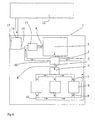
- Fig. 4 shows an alternative embodiment of fig. 3 in which there is ar ranged a heat exchanger 18 for the recover of heat from the fluid in the return conduit 10 to the fluid in the conduit 6, said heat exchanger being provided by the conduit 6 between the outlet 3 of the compressor 5 and the inlet 7 of the tool 8.
- the heat exchanger 18 is arranged in the conduit 6 upstream the site by the conduit at which the first heat exchanger 16 for heat supply is arranged.
- the device is provided in connection with a combustion engine.
- the tool comprises one or more pneumatically, i.e. without camshaft, operated actuators for the inlet and outlet valves of the cylinders of the engine.
- the first compressor 5 is a piston compressor or a screw compressor. If the engine comprises a compressor for the compression of the air that is to be used together with the fuel by the combustion, this com pressor, preferably, forms the second compressor according to the invention.
- the first heat exchanger is, preferably connected with the exhaust system for the purpose of using hot exhaust gases as a heat exchanging medium.
Landscapes
- Engineering & Computer Science (AREA)
- Mechanical Engineering (AREA)
- General Engineering & Computer Science (AREA)
- Physics & Mathematics (AREA)
- Fluid Mechanics (AREA)
- Chemical & Material Sciences (AREA)
- Analytical Chemistry (AREA)
- Fluid-Pressure Circuits (AREA)
- Percussive Tools And Related Accessories (AREA)
- Portable Nailing Machines And Staplers (AREA)
- Spinning Or Twisting Of Yarns (AREA)
Claims (8)
- Verfahren zum Steuern einer Druckfluidströmung in einer pneumatischen Vorrichtung (1), die aufweist- einen im Wesentlichen geschlossenen Druckfluidkreislauf (2),- mindestens einen Kompressor (5) zur Erhöhung des Drucks des Druckfluids im Kreislauf, wobei der Kompressor einen Einlass (4) und einen Auslass (3) aufweist,- ein durch das Druckfluid im Kreislauf betriebenes Werkzeug (8), durch das das Druckfluid im Kreislauf vom Auslass (3) zum Einlass (4) des Kompressors (5) transportiert wird,- worin ein durch den Kompressor (5) ausgebildeter Druck und eine Belastung am Werkzeug (8) so gesteuert werden, dass stromabwärts vom Werkzeug (8) ein Rückdruck im Kreislauf erhalten wird, der den Druck der umgebenden Atmosphäre übersteigt, dadurch gekennzeichnet, dass der Kreislauf einen Rückführkanal (10) aufweist, und dass ein Wärmeaustauscher (17) verwendet wird, um das im Rückführkanal (10) vorhandene Druckfluid zu kühlen.
- Verfahren nach Anspruch 1, dadurch gekennzeichnet, dass zur Kompensation von Druckfluidverlusten im Kreislauf ein Druckfluid von einer Druckfluidquelle (12) stromabwärts vom Werkzeug (8) dem Kreislauf zugeführt wird.
- Verfahren nach Anspruch 1 oder 2, dadurch gekennzeichnet, dass der Kreislauf einen Druckfluidkanal (6) aufweist, der vom Kompressor (5) zum Werkzeug (8) verläuft, und dadurch, dass der Kanal zum Zweck der Verringerung des Wärmeaustauschs zwischen dem Druckfluid und der Umgebung isoliert ist.
- Verfahren nach einem der Ansprüche 1 bis 3, dadurch gekennzeichnet, dass der Kreislauf einen Druckfluidkanal (6) aufweist, der vom Kompressor (5) zum Werkzeug (8) verläuft, und dadurch, dass Wärme aus einer externen Wärmequelle (16) zum Zweck der Aufrechterhaltung oder Erhöhung der Temperatur des Druckfluids in diesem Kanal zugeführt wird.
- Vorrichtung für die pneumatische Betätigung eines Werkzeugs, umfassend- einen im Wesentlichen geschlossenen Druckfluidkreislauf (2),- mindestens einen Kompressor (5) zur Erhöhung des Drucks des Druckfluids im Kreislauf, wobei der Kompressor (5) einen Einlass (4) und einen Auslass (3) aufweist,- ein durch das Druckfluid im Kreislauf betriebenes Werkzeug (8), durch das das Druckfluid im Kreislauf vom Auslass (3) zum Einlass (4) des Kompressors (5) transportiert wird, worin der durch den Kompressor (5) und die durch das Werkzeug (8) angenommene Belastung so eingestellt werden, dass der Rückdruck des Druckfluids stromabwärts vom Werkzeug (8) höher ist als der Druck der umgebenden Atmosphäre, dadurch gekennzeichnet, dass sie einen mittels des Rückführkanals (10) angeordneten Wärmeaustauschers (17) zum Kühlen des Druckfluids im Rückführkanal (10) aufweist.
- Vorrichtung nach Anspruch 5, dadurch gekennzeichnet, dass sie eine Druckfluidquelle (12) aufweist, durch die das Druckfluid zu einem Einlass des Kompressors (5) geführt wird, wobei der Druck in der Druckfluidquelle (12) höher ist als der Druck im Rückführkanal (10).
- Vorrichtung nach Anspruch 5 oder 6, dadurch gekennzeichnet, dass sie einen Wärmeaustauscher (16) aufweist, über den Wärme zwischen dem Druckfluid im Kreislauf stromabwärts vom Kompressor (5) und stromaufwärts vom Werkzeug (8) und einer externen Wärmequelle ausgetauscht wird.
- Vorrichtung nach Anspruch 7, dadurch gekennzeichnet, dass die Vorrichtung an einem Verbrennungsmotor vorgesehen ist und dass die Wärmequelle ein(e) durch den Verbrennungsmotor erwärmtes Fluid oder Substanz aufweist.
Applications Claiming Priority (2)
| Application Number | Priority Date | Filing Date | Title |
|---|---|---|---|
| SE0301457A SE0301457L (sv) | 2003-05-20 | 2003-05-20 | Metod och anordning för pneumatisk drivning av ett verktyg |
| PCT/SE2004/000783 WO2004104417A1 (en) | 2003-05-20 | 2004-05-19 | A method and device for the pneumatic operation of a tool |
Publications (2)
| Publication Number | Publication Date |
|---|---|
| EP1625302A1 EP1625302A1 (de) | 2006-02-15 |
| EP1625302B1 true EP1625302B1 (de) | 2007-07-25 |
Family
ID=20291346
Family Applications (1)
| Application Number | Title | Priority Date | Filing Date |
|---|---|---|---|
| EP04734021A Expired - Lifetime EP1625302B1 (de) | 2003-05-20 | 2004-05-19 | Verfahren und vorrichtung zur druckluftbetätigung eines werkzeugs |
Country Status (11)
| Country | Link |
|---|---|
| US (1) | US7328575B2 (de) |
| EP (1) | EP1625302B1 (de) |
| JP (1) | JP2007511712A (de) |
| KR (1) | KR20060012305A (de) |
| CN (1) | CN100412369C (de) |
| AT (1) | ATE368182T1 (de) |
| DE (1) | DE602004007792T2 (de) |
| ES (1) | ES2290715T3 (de) |
| RU (1) | RU2353809C2 (de) |
| SE (1) | SE0301457L (de) |
| WO (1) | WO2004104417A1 (de) |
Families Citing this family (36)
| Publication number | Priority date | Publication date | Assignee | Title |
|---|---|---|---|---|
| US8245724B2 (en) | 2007-07-06 | 2012-08-21 | Wfk & Associates, Llc | Pneumatic system for residential use |
| US8250863B2 (en) | 2008-04-09 | 2012-08-28 | Sustainx, Inc. | Heat exchange with compressed gas in energy-storage systems |
| US8225606B2 (en) | 2008-04-09 | 2012-07-24 | Sustainx, Inc. | Systems and methods for energy storage and recovery using rapid isothermal gas expansion and compression |
| WO2009126784A2 (en) | 2008-04-09 | 2009-10-15 | Sustainx, Inc. | Systems and methods for energy storage and recovery using compressed gas |
| US8240140B2 (en) | 2008-04-09 | 2012-08-14 | Sustainx, Inc. | High-efficiency energy-conversion based on fluid expansion and compression |
| US8479505B2 (en) | 2008-04-09 | 2013-07-09 | Sustainx, Inc. | Systems and methods for reducing dead volume in compressed-gas energy storage systems |
| US8474255B2 (en) | 2008-04-09 | 2013-07-02 | Sustainx, Inc. | Forming liquid sprays in compressed-gas energy storage systems for effective heat exchange |
| US7958731B2 (en) | 2009-01-20 | 2011-06-14 | Sustainx, Inc. | Systems and methods for combined thermal and compressed gas energy conversion systems |
| US8037678B2 (en) * | 2009-09-11 | 2011-10-18 | Sustainx, Inc. | Energy storage and generation systems and methods using coupled cylinder assemblies |
| US8677744B2 (en) | 2008-04-09 | 2014-03-25 | SustaioX, Inc. | Fluid circulation in energy storage and recovery systems |
| US7802426B2 (en) | 2008-06-09 | 2010-09-28 | Sustainx, Inc. | System and method for rapid isothermal gas expansion and compression for energy storage |
| US20100307156A1 (en) * | 2009-06-04 | 2010-12-09 | Bollinger Benjamin R | Systems and Methods for Improving Drivetrain Efficiency for Compressed Gas Energy Storage and Recovery Systems |
| US8359856B2 (en) | 2008-04-09 | 2013-01-29 | Sustainx Inc. | Systems and methods for efficient pumping of high-pressure fluids for energy storage and recovery |
| US8448433B2 (en) | 2008-04-09 | 2013-05-28 | Sustainx, Inc. | Systems and methods for energy storage and recovery using gas expansion and compression |
| SE533463C2 (sv) * | 2009-02-26 | 2010-10-05 | Stroemsholmen Ab | Avbalanseringsanordning för avbalansering av två relativt varandra rörliga delar innefattande en gasfjäder samt metod för avbalansering |
| US7963110B2 (en) | 2009-03-12 | 2011-06-21 | Sustainx, Inc. | Systems and methods for improving drivetrain efficiency for compressed gas energy storage |
| US8104274B2 (en) | 2009-06-04 | 2012-01-31 | Sustainx, Inc. | Increased power in compressed-gas energy storage and recovery |
| WO2011056855A1 (en) | 2009-11-03 | 2011-05-12 | Sustainx, Inc. | Systems and methods for compressed-gas energy storage using coupled cylinder assemblies |
| US8191362B2 (en) | 2010-04-08 | 2012-06-05 | Sustainx, Inc. | Systems and methods for reducing dead volume in compressed-gas energy storage systems |
| US8171728B2 (en) | 2010-04-08 | 2012-05-08 | Sustainx, Inc. | High-efficiency liquid heat exchange in compressed-gas energy storage systems |
| US8234863B2 (en) | 2010-05-14 | 2012-08-07 | Sustainx, Inc. | Forming liquid sprays in compressed-gas energy storage systems for effective heat exchange |
| ITMI20100189U1 (it) * | 2010-06-04 | 2011-12-05 | Revicart S R L | Apparecchiatura di trasferimento per un fine linea di una macchina piegaincolla. |
| US8495872B2 (en) | 2010-08-20 | 2013-07-30 | Sustainx, Inc. | Energy storage and recovery utilizing low-pressure thermal conditioning for heat exchange with high-pressure gas |
| US8578708B2 (en) | 2010-11-30 | 2013-11-12 | Sustainx, Inc. | Fluid-flow control in energy storage and recovery systems |
| EP2715075A2 (de) | 2011-05-17 | 2014-04-09 | Sustainx, Inc. | Systeme und verfahren für effizienten zweiphasigen wärmetransfer in druckluftenergiespeichersystemen |
| US20130091834A1 (en) | 2011-10-14 | 2013-04-18 | Sustainx, Inc. | Dead-volume management in compressed-gas energy storage and recovery systems |
| US9650215B2 (en) | 2013-05-17 | 2017-05-16 | Intelligrated Headquarters Llc | Robotic carton unloader |
| US9315345B2 (en) | 2013-08-28 | 2016-04-19 | Intelligrated Headquarters Llc | Robotic carton unloader |
| US9487361B2 (en) | 2013-05-17 | 2016-11-08 | Intelligrated Headquarters Llc | Robotic carton unloader |
| CN105473474B (zh) | 2013-05-17 | 2018-01-23 | 因特利格兰特总部有限责任公司 | 机器人纸箱卸载机 |
| US9493316B2 (en) | 2013-07-30 | 2016-11-15 | Intelligrated Headquarters Llc | Robotic carton unloader |
| US9623569B2 (en) | 2014-03-31 | 2017-04-18 | Intelligrated Headquarters, Llc | Autonomous truck loader and unloader |
| CN109715536B (zh) | 2016-09-14 | 2021-04-30 | 因特利格雷特总部有限责任公司 | 机器人纸箱卸载机 |
| US10597235B2 (en) | 2016-10-20 | 2020-03-24 | Intelligrated Headquarters, Llc | Carton unloader tool for jam recovery |
| US10077572B1 (en) * | 2017-04-19 | 2018-09-18 | Hmt, Llc | Systems and methods for lifting and positioning a roof for installation on a storage tank |
| US10995893B1 (en) * | 2019-02-12 | 2021-05-04 | Anthony Aguilar | Manifold for compressed air |
Family Cites Families (16)
| Publication number | Priority date | Publication date | Assignee | Title |
|---|---|---|---|---|
| GB190800449A (en) * | 1908-01-08 | 1909-01-07 | Harold Fletcher Massey | Improvements in and relating to Hammers and other Machines and Air-compressors for Driving them. |
| US3398533A (en) * | 1961-11-13 | 1968-08-27 | Michael H. Wolfbauer Jr. | Closed air compressor and motor system |
| JPS5193095U (de) * | 1975-01-23 | 1976-07-26 | ||
| JPS5486080A (en) * | 1977-12-21 | 1979-07-09 | Nippon Air Brake Co | Closed circuit apparatus for pneumatic actuator |
| JPS54101502U (de) * | 1977-12-27 | 1979-07-17 | ||
| JPS54101503U (de) * | 1977-12-27 | 1979-07-17 | ||
| JPS59140904A (ja) * | 1983-01-29 | 1984-08-13 | Sankiyougumi Kogyosho:Kk | 動力伝達装置 |
| JPH0571508A (ja) * | 1991-03-29 | 1993-03-23 | Mitsubishi Heavy Ind Ltd | ガス圧サーボシステム |
| JP3375738B2 (ja) * | 1994-06-30 | 2003-02-10 | シスメックス株式会社 | 加圧空気供給装置 |
| JPH08296607A (ja) * | 1995-04-25 | 1996-11-12 | Smc Corp | 流体圧アクチュエータの駆動回路 |
| WO2002004790A1 (en) * | 2000-07-10 | 2002-01-17 | Cargine Engineering Ab | Pressure pulse generator |
| SE520993C2 (sv) | 2000-07-10 | 2003-09-23 | Cargine Engineering Ab | Tryckpulsgenerator |
| JP2002031107A (ja) * | 2000-07-13 | 2002-01-31 | Sumitomo Heavy Ind Ltd | 空圧機器の駆動方法及び装置 |
| MXPA03004752A (es) * | 2000-11-28 | 2005-10-18 | Shep Ltd | Sistemas de almacenamiento de energia hidraulica. |
| JP3676669B2 (ja) * | 2000-12-04 | 2005-07-27 | Smc株式会社 | 空気圧装置 |
| JP3818980B2 (ja) * | 2003-06-02 | 2006-09-06 | Smc株式会社 | 流体回路システム |
-
2003
- 2003-05-20 SE SE0301457A patent/SE0301457L/sv not_active Application Discontinuation
-
2004
- 2004-05-19 KR KR1020057021979A patent/KR20060012305A/ko not_active Withdrawn
- 2004-05-19 DE DE602004007792T patent/DE602004007792T2/de not_active Expired - Lifetime
- 2004-05-19 EP EP04734021A patent/EP1625302B1/de not_active Expired - Lifetime
- 2004-05-19 AT AT04734021T patent/ATE368182T1/de not_active IP Right Cessation
- 2004-05-19 ES ES04734021T patent/ES2290715T3/es not_active Expired - Lifetime
- 2004-05-19 JP JP2006532202A patent/JP2007511712A/ja active Pending
- 2004-05-19 WO PCT/SE2004/000783 patent/WO2004104417A1/en not_active Ceased
- 2004-05-19 US US10/556,407 patent/US7328575B2/en not_active Expired - Lifetime
- 2004-05-19 CN CNB2004800138853A patent/CN100412369C/zh not_active Expired - Fee Related
- 2004-05-19 RU RU2005136526/06A patent/RU2353809C2/ru not_active IP Right Cessation
Also Published As
| Publication number | Publication date |
|---|---|
| KR20060012305A (ko) | 2006-02-07 |
| ES2290715T3 (es) | 2008-02-16 |
| CN1791749A (zh) | 2006-06-21 |
| SE0301457L (sv) | 2004-11-21 |
| DE602004007792D1 (de) | 2007-09-06 |
| SE0301457D0 (sv) | 2003-05-20 |
| ATE368182T1 (de) | 2007-08-15 |
| CN100412369C (zh) | 2008-08-20 |
| US20060272324A1 (en) | 2006-12-07 |
| DE602004007792T2 (de) | 2008-04-30 |
| RU2005136526A (ru) | 2006-06-10 |
| EP1625302A1 (de) | 2006-02-15 |
| RU2353809C2 (ru) | 2009-04-27 |
| JP2007511712A (ja) | 2007-05-10 |
| WO2004104417A1 (en) | 2004-12-02 |
| US7328575B2 (en) | 2008-02-12 |
Similar Documents
| Publication | Publication Date | Title |
|---|---|---|
| US7328575B2 (en) | Method and device for the pneumatic operation of a tool | |
| US5095709A (en) | Liquid nitrogen to gas system | |
| US9896974B2 (en) | Multiple organic rankine cycle systems and methods | |
| JP4184973B2 (ja) | キャビネット冷却 | |
| US2991632A (en) | Refrigeration system | |
| KR102045273B1 (ko) | 히트 펌프 | |
| SE9800619D0 (sv) | Kyl- och värmesystem | |
| CN103443438B (zh) | 固定用内燃机的吸气冷却装置 | |
| US4420950A (en) | Plant for utilization of low-potential waste heat of a gas-pipeline compressor station | |
| CN100370195C (zh) | 热电联产系统 | |
| JP7309593B2 (ja) | 排熱回収システム、及び、それに用いる気体圧縮機 | |
| GB2339890A (en) | Heat recovery from refrigeration and air conditioning systems | |
| US2992536A (en) | External combustion gas engine | |
| CN213067201U (zh) | 一种离心式空气压缩机余热回收装置 | |
| EP1438536B1 (de) | Klimaregelungsanlage | |
| EP3899214B1 (de) | Ein system zur rückgewinnung von energie in restgasen | |
| KR20040029256A (ko) | 폐열 회수식 열 펌프 | |
| CN113756768A (zh) | 烟气高压注气驱油一橇化油田设备 | |
| CN102230420A (zh) | 低温排气发动机 | |
| CN219974615U (zh) | 一种工业发电用内燃机缸套水冷却提升系统 | |
| JPH0581736B2 (de) | ||
| PL235574B1 (pl) | Sprężarka tłokowa do sprężania gazu ziemnego na stacjach redukcyjnych | |
| RU2182290C2 (ru) | Холодильная установка | |
| RU2068351C1 (ru) | Система питания сжатым газом тормозных устройств | |
| TH2101008188A (th) | วิธีการควบคุมการไหลกลับของน้ำมันของระบบมัลติ-สปลิทแบบมัลติฟังก์ชันด้วยวาล์วสี่ทางสองตัว |
Legal Events
| Date | Code | Title | Description |
|---|---|---|---|
| PUAI | Public reference made under article 153(3) epc to a published international application that has entered the european phase |
Free format text: ORIGINAL CODE: 0009012 |
|
| 17P | Request for examination filed |
Effective date: 20051018 |
|
| AK | Designated contracting states |
Kind code of ref document: A1 Designated state(s): AT BE BG CH CY CZ DE DK EE ES FI FR GB GR HU IE IT LI LU MC NL PL PT RO SE SI SK TR |
|
| DAX | Request for extension of the european patent (deleted) | ||
| GRAP | Despatch of communication of intention to grant a patent |
Free format text: ORIGINAL CODE: EPIDOSNIGR1 |
|
| GRAS | Grant fee paid |
Free format text: ORIGINAL CODE: EPIDOSNIGR3 |
|
| GRAA | (expected) grant |
Free format text: ORIGINAL CODE: 0009210 |
|
| AK | Designated contracting states |
Kind code of ref document: B1 Designated state(s): AT BE BG CH CY CZ DE DK EE ES FI FR GB GR HU IE IT LI LU MC NL PL PT RO SE SI SK TR |
|
| REG | Reference to a national code |
Ref country code: GB Ref legal event code: FG4D |
|
| RIN1 | Information on inventor provided before grant (corrected) |
Inventor name: HEDMAN, MATS |
|
| REG | Reference to a national code |
Ref country code: CH Ref legal event code: EP |
|
| REG | Reference to a national code |
Ref country code: IE Ref legal event code: FG4D |
|
| REF | Corresponds to: |
Ref document number: 602004007792 Country of ref document: DE Date of ref document: 20070906 Kind code of ref document: P |
|
| REG | Reference to a national code |
Ref country code: SE Ref legal event code: TRGR |
|
| ET | Fr: translation filed | ||
| PG25 | Lapsed in a contracting state [announced via postgrant information from national office to epo] |
Ref country code: PT Free format text: LAPSE BECAUSE OF FAILURE TO SUBMIT A TRANSLATION OF THE DESCRIPTION OR TO PAY THE FEE WITHIN THE PRESCRIBED TIME-LIMIT Effective date: 20071226 Ref country code: NL Free format text: LAPSE BECAUSE OF FAILURE TO SUBMIT A TRANSLATION OF THE DESCRIPTION OR TO PAY THE FEE WITHIN THE PRESCRIBED TIME-LIMIT Effective date: 20070725 Ref country code: BG Free format text: LAPSE BECAUSE OF FAILURE TO SUBMIT A TRANSLATION OF THE DESCRIPTION OR TO PAY THE FEE WITHIN THE PRESCRIBED TIME-LIMIT Effective date: 20071025 Ref country code: FI Free format text: LAPSE BECAUSE OF FAILURE TO SUBMIT A TRANSLATION OF THE DESCRIPTION OR TO PAY THE FEE WITHIN THE PRESCRIBED TIME-LIMIT Effective date: 20070725 |
|
| REG | Reference to a national code |
Ref country code: CH Ref legal event code: PL |
|
| NLV1 | Nl: lapsed or annulled due to failure to fulfill the requirements of art. 29p and 29m of the patents act | ||
| REG | Reference to a national code |
Ref country code: ES Ref legal event code: FG2A Ref document number: 2290715 Country of ref document: ES Kind code of ref document: T3 |
|
| PG25 | Lapsed in a contracting state [announced via postgrant information from national office to epo] |
Ref country code: PL Free format text: LAPSE BECAUSE OF FAILURE TO SUBMIT A TRANSLATION OF THE DESCRIPTION OR TO PAY THE FEE WITHIN THE PRESCRIBED TIME-LIMIT Effective date: 20070725 Ref country code: LI Free format text: LAPSE BECAUSE OF FAILURE TO SUBMIT A TRANSLATION OF THE DESCRIPTION OR TO PAY THE FEE WITHIN THE PRESCRIBED TIME-LIMIT Effective date: 20070725 Ref country code: CH Free format text: LAPSE BECAUSE OF FAILURE TO SUBMIT A TRANSLATION OF THE DESCRIPTION OR TO PAY THE FEE WITHIN THE PRESCRIBED TIME-LIMIT Effective date: 20070725 Ref country code: AT Free format text: LAPSE BECAUSE OF FAILURE TO SUBMIT A TRANSLATION OF THE DESCRIPTION OR TO PAY THE FEE WITHIN THE PRESCRIBED TIME-LIMIT Effective date: 20070725 |
|
| PG25 | Lapsed in a contracting state [announced via postgrant information from national office to epo] |
Ref country code: BE Free format text: LAPSE BECAUSE OF FAILURE TO SUBMIT A TRANSLATION OF THE DESCRIPTION OR TO PAY THE FEE WITHIN THE PRESCRIBED TIME-LIMIT Effective date: 20070725 |
|
| PG25 | Lapsed in a contracting state [announced via postgrant information from national office to epo] |
Ref country code: GR Free format text: LAPSE BECAUSE OF FAILURE TO SUBMIT A TRANSLATION OF THE DESCRIPTION OR TO PAY THE FEE WITHIN THE PRESCRIBED TIME-LIMIT Effective date: 20071026 Ref country code: DK Free format text: LAPSE BECAUSE OF FAILURE TO SUBMIT A TRANSLATION OF THE DESCRIPTION OR TO PAY THE FEE WITHIN THE PRESCRIBED TIME-LIMIT Effective date: 20070725 |
|
| PG25 | Lapsed in a contracting state [announced via postgrant information from national office to epo] |
Ref country code: SK Free format text: LAPSE BECAUSE OF FAILURE TO SUBMIT A TRANSLATION OF THE DESCRIPTION OR TO PAY THE FEE WITHIN THE PRESCRIBED TIME-LIMIT Effective date: 20070725 Ref country code: CZ Free format text: LAPSE BECAUSE OF FAILURE TO SUBMIT A TRANSLATION OF THE DESCRIPTION OR TO PAY THE FEE WITHIN THE PRESCRIBED TIME-LIMIT Effective date: 20070725 |
|
| PLBE | No opposition filed within time limit |
Free format text: ORIGINAL CODE: 0009261 |
|
| STAA | Information on the status of an ep patent application or granted ep patent |
Free format text: STATUS: NO OPPOSITION FILED WITHIN TIME LIMIT |
|
| PG25 | Lapsed in a contracting state [announced via postgrant information from national office to epo] |
Ref country code: RO Free format text: LAPSE BECAUSE OF FAILURE TO SUBMIT A TRANSLATION OF THE DESCRIPTION OR TO PAY THE FEE WITHIN THE PRESCRIBED TIME-LIMIT Effective date: 20070725 |
|
| 26N | No opposition filed |
Effective date: 20080428 |
|
| PG25 | Lapsed in a contracting state [announced via postgrant information from national office to epo] |
Ref country code: MC Free format text: LAPSE BECAUSE OF NON-PAYMENT OF DUE FEES Effective date: 20080531 |
|
| PG25 | Lapsed in a contracting state [announced via postgrant information from national office to epo] |
Ref country code: IE Free format text: LAPSE BECAUSE OF NON-PAYMENT OF DUE FEES Effective date: 20080519 Ref country code: EE Free format text: LAPSE BECAUSE OF FAILURE TO SUBMIT A TRANSLATION OF THE DESCRIPTION OR TO PAY THE FEE WITHIN THE PRESCRIBED TIME-LIMIT Effective date: 20070725 |
|
| PG25 | Lapsed in a contracting state [announced via postgrant information from national office to epo] |
Ref country code: SI Free format text: LAPSE BECAUSE OF FAILURE TO SUBMIT A TRANSLATION OF THE DESCRIPTION OR TO PAY THE FEE WITHIN THE PRESCRIBED TIME-LIMIT Effective date: 20070725 |
|
| PG25 | Lapsed in a contracting state [announced via postgrant information from national office to epo] |
Ref country code: CY Free format text: LAPSE BECAUSE OF FAILURE TO SUBMIT A TRANSLATION OF THE DESCRIPTION OR TO PAY THE FEE WITHIN THE PRESCRIBED TIME-LIMIT Effective date: 20070725 |
|
| PG25 | Lapsed in a contracting state [announced via postgrant information from national office to epo] |
Ref country code: LU Free format text: LAPSE BECAUSE OF NON-PAYMENT OF DUE FEES Effective date: 20080519 Ref country code: HU Free format text: LAPSE BECAUSE OF FAILURE TO SUBMIT A TRANSLATION OF THE DESCRIPTION OR TO PAY THE FEE WITHIN THE PRESCRIBED TIME-LIMIT Effective date: 20080126 |
|
| PG25 | Lapsed in a contracting state [announced via postgrant information from national office to epo] |
Ref country code: TR Free format text: LAPSE BECAUSE OF FAILURE TO SUBMIT A TRANSLATION OF THE DESCRIPTION OR TO PAY THE FEE WITHIN THE PRESCRIBED TIME-LIMIT Effective date: 20070725 |
|
| REG | Reference to a national code |
Ref country code: FR Ref legal event code: ST Effective date: 20120131 |
|
| PG25 | Lapsed in a contracting state [announced via postgrant information from national office to epo] |
Ref country code: FR Free format text: LAPSE BECAUSE OF NON-PAYMENT OF DUE FEES Effective date: 20110531 |
|
| REG | Reference to a national code |
Ref country code: FR Ref legal event code: D3 Effective date: 20120529 |
|
| PGRI | Patent reinstated in contracting state [announced from national office to epo] |
Ref country code: FR Effective date: 20120529 |
|
| REG | Reference to a national code |
Ref country code: FR Ref legal event code: PLFP Year of fee payment: 13 |
|
| PGFP | Annual fee paid to national office [announced via postgrant information from national office to epo] |
Ref country code: GB Payment date: 20161123 Year of fee payment: 13 Ref country code: FR Payment date: 20161116 Year of fee payment: 13 |
|
| PGFP | Annual fee paid to national office [announced via postgrant information from national office to epo] |
Ref country code: ES Payment date: 20161122 Year of fee payment: 13 Ref country code: IT Payment date: 20161122 Year of fee payment: 13 |
|
| GBPC | Gb: european patent ceased through non-payment of renewal fee |
Effective date: 20170519 |
|
| REG | Reference to a national code |
Ref country code: FR Ref legal event code: ST Effective date: 20180131 |
|
| PG25 | Lapsed in a contracting state [announced via postgrant information from national office to epo] |
Ref country code: GB Free format text: LAPSE BECAUSE OF NON-PAYMENT OF DUE FEES Effective date: 20170519 |
|
| PG25 | Lapsed in a contracting state [announced via postgrant information from national office to epo] |
Ref country code: FR Free format text: LAPSE BECAUSE OF NON-PAYMENT OF DUE FEES Effective date: 20170531 Ref country code: IT Free format text: LAPSE BECAUSE OF NON-PAYMENT OF DUE FEES Effective date: 20170519 |
|
| REG | Reference to a national code |
Ref country code: ES Ref legal event code: FD2A Effective date: 20180705 |
|
| PG25 | Lapsed in a contracting state [announced via postgrant information from national office to epo] |
Ref country code: ES Free format text: LAPSE BECAUSE OF NON-PAYMENT OF DUE FEES Effective date: 20170520 |
|
| PGFP | Annual fee paid to national office [announced via postgrant information from national office to epo] |
Ref country code: DE Payment date: 20190520 Year of fee payment: 16 |
|
| PGFP | Annual fee paid to national office [announced via postgrant information from national office to epo] |
Ref country code: SE Payment date: 20190516 Year of fee payment: 16 |
|
| REG | Reference to a national code |
Ref country code: DE Ref legal event code: R119 Ref document number: 602004007792 Country of ref document: DE |
|
| PG25 | Lapsed in a contracting state [announced via postgrant information from national office to epo] |
Ref country code: SE Free format text: LAPSE BECAUSE OF NON-PAYMENT OF DUE FEES Effective date: 20200520 |
|
| PG25 | Lapsed in a contracting state [announced via postgrant information from national office to epo] |
Ref country code: DE Free format text: LAPSE BECAUSE OF NON-PAYMENT OF DUE FEES Effective date: 20201201 |